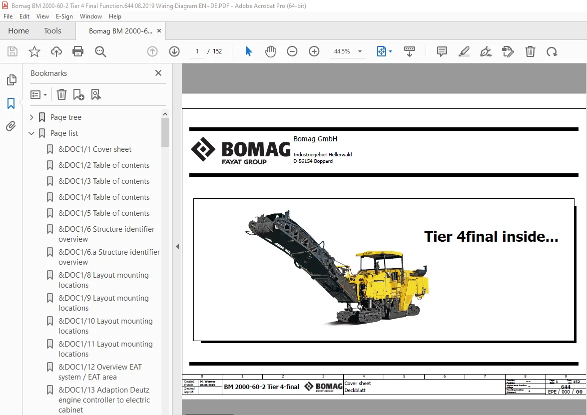
Bomag BM 2000-60-2 Tier 4 Final Function.644 Wiring Diagram Manual EN_DE PDF
$26.95
Bomag BM 2000-60-2 Tier 4 Final Function.644 Wiring Diagram Manual EN_DE – PDF DOWNLOAD
Description
Bomag BM 2000-60-2 Tier 4 Final Function.644 Wiring Diagram Manual EN_DE – PDF DOWNLOAD
FILE DETAILS:
Bomag BM 2000-60-2 Tier 4 Final Function.644 Wiring Diagram Manual EN_DE – PDF DOWNLOAD
Language : English
Pages : 152
Downloadable : Yes
File Type : PDF
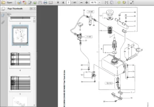
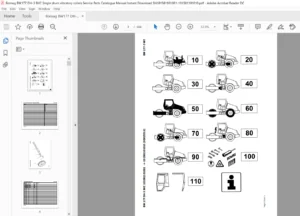
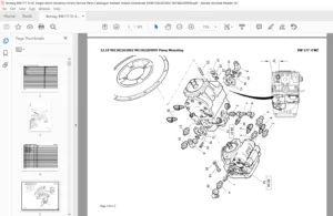
IMAGES PREVIEW OF THE MANUAL:
TABLE OF CONTENTS:
Bomag BM 2000-60-2 Tier 4 Final Function.644 Wiring Diagram Manual EN_DE – PDF DOWNLOAD
Page tree 1
&DOC1 Leading documentation 1
1 Cover sheet 1
2 Table of contents 2
3 Table of contents 3
4 Table of contents 4
5 Table of contents 5
6 Structure identifier overview 6
6 a Structure identifier overview 7
8 Layout mounting locations 8
9 Layout mounting locations 9
10 Layout mounting locations 10
11 Layout mounting locations 11
12 Overview EAT system / EAT area 12
13 Adaption Deutz engine controller to electric cabinet 13
14 Overview CAN Engine Stage 4f 14
&EFS Circuit diagram 15
=BM Basic milling machine 15
==SUPL Supply 15
+B13 Battery compartment 15
15 Battery compartment 15
+B20 Electric cabinet 16
16 Power supply 24V 16
17 Emergency stop switch 17
==ENGI Engine 18
+B20 Electric cabinet 18
18 Engine speed adjustment and preheat 18
+FRA Frame 19
19 Engine – Deutz Tier4f, machine 19
20 Engine – Deutz Tier4f, motor 20
21 Engine – Deutz Tier4f, motor 21
22 Engine – Deutz Tier 4f, SCR system 22
23 Engine – Deutz Tier4f, SCR System 23
24 Engine – Deutz Tier 4f, SCR NOX Waste 24
25 Deutz TCD 4 1/6 1 – Exhaust aftertreatment Kat 1 25
26 Deutz TCD 4 1/6 1 – Exhaust aftertreatment Kat 2 26
+B14 Engine compartment 27
27 Blower, engine cooler 27
==COM Communication 28
+B17 Left panel 28
28 CAN communication left panel 28
+B18 Central panel 29
29 CAN communication central panel 29
+B19 Right panel 30
30 CAN communication right panel 30
+B20 Electric cabinet 31
31 CAN communication e-box 31
32 CAN communication e-box 32
+B14 Engine compartment 33
33 CAN communication engine compartment 33
==DATA Data collector / signals 34
+B20 Electric cabinet 34
34 Monitoring, Failure indicators 34
35 Monitoring sensors 35
36 Alarm function 36
37 Warning horn 37
38 BOAMG Telematics 38
==DRIV Drive functions 39
+B17 Left panel 39
39 driving system operation 39
40 driving system operation 40
+B14 Engine compartment 41
41 driving system valves and sensors 41
==STEER Steering functions 42
+B17 Left panel 42
42 Actuation steering functions front axle 42
43 Actuation steering functions rear axle 43
44 Actuation steering modes 44
+B20 Electric cabinet 45
45 Actuation steering functions rear boxes 45
46 Steering functions / sensors 46
+B14 Engine compartment 47
47 Steering functions / valves 47
==MILL Milling functions 48
+B20 Electric cabinet 48
48 Rear scraper milling box 48
49 Rear scraper milling box 49
50 Front scraper milling box 50
51 Side scrapers milling box 51
52 Hight adjustment, actuation 52
53 Hight adjustment, actuation and sensors 53
54 Leveling system, controller and attachments Display 54
55 Leveling system, sensor attachments 55
+B14 Engine compartment 56
56 Milling Box 56
57 Rear scraper milling box / valves 57
58 Front scraper milling box / valves 58
59 Side scrapers milling box / valves 59
60 Hight adjustment, valves 60
==WORK workimg functions 61
+B20 Electric cabinet 61
61 Conveyor, adjustment position, speed and activation 61
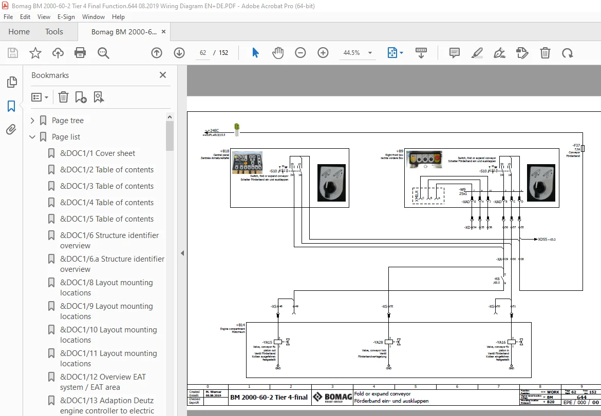
62 Fold or expand conveyor 62
63 Conveyor attached sensors 63
+B14 Engine compartment 64
64 conveyor belt drive / valves 64
65 conveyor belt drive / valves 65
==WSPR Water spraying 66
+B17 Left panel 66
66 Water spray system actuation and pause 66
+B20 Electric cabinet 67
67 Water system 67
+B14 Engine compartment 68
68 Water spray system, valves 68
==ILUM Lighting 69
+B20 Electric cabinet 69
69 Working lights / actuation 69
+FRA Frame 70
70 Working lights, rotary beacon 70
==COMF Comfort devices 71
+B20 Electric cabinet 71
71 Roof, engine hood and emergency service pump 71
72 Fuel fill 72
&DOC2 Reports and drawings 73
73 Component-Listing 73
74 Component-Listing 74
75 Component-Listing 75
76 Component-Listing 76
77 Component-Listing 77
78 Component-Listing 78
79 Component-Listing 79
80 Component-Listing 80
81 Component-Listing 81
82 Component-Listing 82
83 Component-Listing 83
84 Component-Listing 84
85 Component-Listing 85
86 Terminal diagram 86
87 Terminal diagram 87
88 Terminal diagram 88
89 Terminal diagram 89
90 Terminal diagram 90
91 Terminal diagram 91
92 Terminal diagram 92
93 Terminal diagram 93
94 Terminal diagram 94
95 Pin overview U1 95
96 Pin overview U1 96
97 Pin overview U1 97
98 Pin overview U1 98
99 Pin overview U1 99
100 Pin overview U1 100
101 Pin overview U2 101
102 Pin overview U2 102
103 Pin overview U2 103
104 Pin overview U2 104
105 Pin overview U2 105
106 Pin overview U3 106
107 Pin overview U3 107
108 Pin overview U3 108
109 Pin overview U3 109
110 Pin overview U3 110
111 Pin overview U4 111
112 Pin overview U4 112
113 Pin overview U4 113
114 Pin overview U4 114
115 Pin overview U4 115
116 Pin overview U5 116
117 Pin overview U5 117
118 Pin overview U5 118
119 Plug diagram 119
120 Plug diagram 120
121 Plug diagram 121
122 Plug diagram 122
123 Plug diagram 123
124 Plug diagram 124
125 Plug diagram 125
126 Plug diagram 126
127 Plug diagram 127
128 Plug diagram 128
129 Plug diagram 129
130 Plug diagram 130
131 Plug diagram 131
132 Plug diagram 132
133 Plug diagram 133
134 Plug diagram 134
135 Plug diagram 135
136 Plug diagram 136
137 Plug diagram 137
138 Plug diagram 138
139 Plug diagram 139
140 Plug diagram 140
141 Plug diagram 141
142 Plug diagram 142
143 Plug diagram 143
144 Illustrations terminal strips 144
145 Illustrations terminal strips 145
146 Illustrations terminal strips 146
147 Illustrations terminal strips 147
148 Illustrations terminal strips 148
149 Illustrations terminal strips 149
150 Illustrations terminal strips 150
151 Illustrations terminal strips 151
152 Illustrations terminal strips 152
Page list 1
&DOC1/1 Cover sheet 1
&DOC1/2 Table of contents 2
&DOC1/3 Table of contents 3
&DOC1/4 Table of contents 4
&DOC1/5 Table of contents 5
&DOC1/6 Structure identifier overview 6
&DOC1/6 a Structure identifier overview 7
&DOC1/8 Layout mounting locations 8
&DOC1/9 Layout mounting locations 9
&DOC1/10 Layout mounting locations 10
&DOC1/11 Layout mounting locations 11
&DOC1/12 Overview EAT system / EAT area 12
&DOC1/13 Adaption Deutz engine controller to electric cabinet 13
&DOC1/14 Overview CAN Engine Stage 4f 14
&EFS==SUPL=BM+B13/15 Battery compartment 15
&EFS==SUPL=BM+B20/16 Power supply 24V 16
&EFS==SUPL=BM+B20/17 Emergency stop switch 17
&EFS==ENGI=BM+B20/18 Engine speed adjustment and preheat 18
&EFS==ENGI=BM+FRA/19 Engine – Deutz Tier4f, machine 19
&EFS==ENGI=BM+FRA/20 Engine – Deutz Tier4f, motor 20
&EFS==ENGI=BM+FRA/21 Engine – Deutz Tier4f, motor 21
&EFS==ENGI=BM+FRA/22 Engine – Deutz Tier 4f, SCR system 22
&EFS==ENGI=BM+FRA/23 Engine – Deutz Tier4f, SCR System 23
&EFS==ENGI=BM+FRA/24 Engine – Deutz Tier 4f, SCR NOX Waste 24
&EFS==ENGI=BM+FRA/25 Deutz TCD 4 1/6 1 – Exhaust aftertreatment Kat 1 25
&EFS==ENGI=BM+FRA/26 Deutz TCD 4 1/6 1 – Exhaust aftertreatment Kat 2 26
&EFS==ENGI=BM+B14/27 Blower, engine cooler 27
&EFS==COM=BM+B17/28 CAN communication left panel 28
&EFS==COM=BM+B18/29 CAN communication central panel 29
&EFS==COM=BM+B19/30 CAN communication right panel 30
&EFS==COM=BM+B20/31 CAN communication e-box 31
&EFS==COM=BM+B20/32 CAN communication e-box 32
&EFS==COM=BM+B14/33 CAN communication engine compartment 33
&EFS==DATA=BM+B20/34 Monitoring, Failure indicators 34
&EFS==DATA=BM+B20/35 Monitoring sensors 35
&EFS==DATA=BM+B20/36 Alarm function 36
&EFS==DATA=BM+B20/37 Warning horn 37
&EFS==DATA=BM+B20/38 BOAMG Telematics 38
&EFS==DRIV=BM+B17/39 driving system operation 39
&EFS==DRIV=BM+B17/40 driving system operation 40
&EFS==DRIV=BM+B14/41 driving system valves and sensors 41
&EFS==STEER=BM+B17/42 Actuation steering functions front axle 42
&EFS==STEER=BM+B17/43 Actuation steering functions rear axle 43
&EFS==STEER=BM+B17/44 Actuation steering modes 44
&EFS==STEER=BM+B20/45 Actuation steering functions rear boxes 45
&EFS==STEER=BM+B20/46 Steering functions / sensors 46
&EFS==STEER=BM+B14/47 Steering functions / valves 47
&EFS==MILL=BM+B20/48 Rear scraper milling box 48
&EFS==MILL=BM+B20/49 Rear scraper milling box 49
&EFS==MILL=BM+B20/50 Front scraper milling box 50
&EFS==MILL=BM+B20/51 Side scrapers milling box 51
&EFS==MILL=BM+B20/52 Hight adjustment, actuation 52
&EFS==MILL=BM+B20/53 Hight adjustment, actuation and sensors 53
&EFS==MILL=BM+B20/54 Leveling system, controller and attachments Display 54
&EFS==MILL=BM+B20/55 Leveling system, sensor attachments 55
&EFS==MILL=BM+B14/56 Milling Box 56
&EFS==MILL=BM+B14/57 Rear scraper milling box / valves 57
&EFS==MILL=BM+B14/58 Front scraper milling box / valves 58
&EFS==MILL=BM+B14/59 Side scrapers milling box / valves 59
&EFS==MILL=BM+B14/60 Hight adjustment, valves 60
&EFS==WORK=BM+B20/61 Conveyor, adjustment position, speed and activation 61
&EFS==WORK=BM+B20/62 Fold or expand conveyor 62
&EFS==WORK=BM+B20/63 Conveyor attached sensors 63
&EFS==WORK=BM+B14/64 conveyor belt drive / valves 64
&EFS==WORK=BM+B14/65 conveyor belt drive / valves 65
&EFS==WSPR=BM+B17/66 Water spray system actuation and pause 66
&EFS==WSPR=BM+B20/67 Water system 67
&EFS==WSPR=BM+B14/68 Water spray system, valves 68
&EFS==ILUM=BM+B20/69 Working lights / actuation 69
&EFS==ILUM=BM+FRA/70 Working lights, rotary beacon 70
&EFS==COMF=BM+B20/71 Roof, engine hood and emergency service pump 71
&EFS==COMF=BM+B20/72 Fuel fill 72
&DOC2/73 Component-Listing 73
&DOC2/74 Component-Listing 74
&DOC2/75 Component-Listing 75
&DOC2/76 Component-Listing 76
&DOC2/77 Component-Listing 77
&DOC2/78 Component-Listing 78
&DOC2/79 Component-Listing 79
&DOC2/80 Component-Listing 80
&DOC2/81 Component-Listing 81
&DOC2/82 Component-Listing 82
&DOC2/83 Component-Listing 83
&DOC2/84 Component-Listing 84
&DOC2/85 Component-Listing 85
&DOC2/86 Terminal diagram 86
&DOC2/87 Terminal diagram 87
&DOC2/88 Terminal diagram 88
&DOC2/89 Terminal diagram 89
&DOC2/90 Terminal diagram 90
&DOC2/91 Terminal diagram 91
&DOC2/92 Terminal diagram 92
&DOC2/93 Terminal diagram 93
&DOC2/94 Terminal diagram 94
&DOC2/95 Pin overview U1 95
&DOC2/96 Pin overview U1 96
&DOC2/97 Pin overview U1 97
&DOC2/98 Pin overview U1 98
&DOC2/99 Pin overview U1 99
&DOC2/100 Pin overview U1 100
&DOC2/101 Pin overview U2 101
&DOC2/102 Pin overview U2 102
&DOC2/103 Pin overview U2 103
&DOC2/104 Pin overview U2 104
&DOC2/105 Pin overview U2 105
&DOC2/106 Pin overview U3 106
&DOC2/107 Pin overview U3 107
&DOC2/108 Pin overview U3 108
&DOC2/109 Pin overview U3 109
&DOC2/110 Pin overview U3 110
&DOC2/111 Pin overview U4 111
&DOC2/112 Pin overview U4 112
&DOC2/113 Pin overview U4 113
&DOC2/114 Pin overview U4 114
&DOC2/115 Pin overview U4 115
&DOC2/116 Pin overview U5 116
&DOC2/117 Pin overview U5 117
&DOC2/118 Pin overview U5 118
&DOC2/119 Plug diagram 119
&DOC2/120 Plug diagram 120
&DOC2/121 Plug diagram 121
&DOC2/122 Plug diagram 122
&DOC2/123 Plug diagram 123
&DOC2/124 Plug diagram 124
&DOC2/125 Plug diagram 125
&DOC2/126 Plug diagram 126
&DOC2/127 Plug diagram 127
&DOC2/128 Plug diagram 128
&DOC2/129 Plug diagram 129
&DOC2/130 Plug diagram 130
&DOC2/131 Plug diagram 131
&DOC2/132 Plug diagram 132
&DOC2/133 Plug diagram 133
&DOC2/134 Plug diagram 134
&DOC2/135 Plug diagram 135
&DOC2/136 Plug diagram 136
&DOC2/137 Plug diagram 137
&DOC2/138 Plug diagram 138
&DOC2/139 Plug diagram 139
&DOC2/140 Plug diagram 140
&DOC2/141 Plug diagram 141
&DOC2/142 Plug diagram 142
&DOC2/143 Plug diagram 143
&DOC2/144 Illustrations terminal strips 144
&DOC2/145 Illustrations terminal strips 145
&DOC2/146 Illustrations terminal strips 146
&DOC2/147 Illustrations terminal strips 147
&DOC2/148 Illustrations terminal strips 148
&DOC2/149 Illustrations terminal strips 149
&DOC2/150 Illustrations terminal strips 150
&DOC2/151 Illustrations terminal strips 151
&DOC2/152 Illustrations terminal strips 152
S.V 08/24