Bomag BW 161 ADO-50 Tandem vibratory roller Service Training Manual – PDF DOWNLOAD
Original price was: $86.95.$31.95Current price is: $31.95.
Bomag BW 161 ADO-50 Tandem vibratory roller Service Training Manual – PDF DOWNLOAD
Description
Bomag BW 161 ADO-50 Tandem vibratory roller Service Training Manual – PDF DOWNLOAD
FILE DETAILS:
Bomag BW 161 ADO-50 Tandem vibratory roller Service Training Manual – PDF DOWNLOAD
Language : English
Pages : 698
Downloadable : Yes
File Type : PDF
Size: 193 MB
DESCRIPTION:
Bomag BW 161 ADO-50 Tandem vibratory roller Service Training Manual – PDF DOWNLOAD
General
This manual:
n addresses the BOMAG customer service or professionally
trained personnel.
n explains the design of the machine and its functions.
n serves as
– document to be used during the training course
– reference book for the purpose of repeating or deepening
the training contents you have learned.
This manual describes components, assemblies and the essential
functions of the machine. (As far as required for the BOMAG After
Sales Service)
Documentation
For the BOMAG machines described in this manual the following
documentation is additionally available:
n Operating and maintenance instructions
n Spare parts catalogue
n Service information (if necessary)
IMAGES PREVIEW OF THE MANUAL:
TABLE OF CONTENTS:
Bomag BW 161 ADO-50 Tandem vibratory roller Service Training Manual – PDF DOWNLOAD
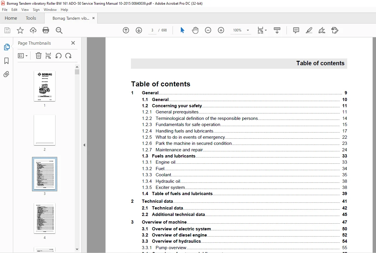
Table of contents 3
1 General 9
1 1 General 10
1 2 Concerning your safety 11
1 2 1 General prerequisites 11
1 2 1 1 General 11
1 2 1 2 Explanations to signal words used: 11
1 2 1 3 Personal protective outfit 12
1 2 1 4 Intended use 13
1 2 1 5 Unintended use 13
1 2 1 6 Unintended use 14
1 2 2 Terminological definition of the responsible persons 14
1 2 2 1 Operating company 14
1 2 2 2 Expert / qualified person 15
1 2 2 3 Driver / operator 15
1 2 3 Fundamentals for safe operation 15
1 2 3 1 Remaining dangers, remaining risks 15
1 2 3 2 Regular safety inspections 16
1 2 3 3 Changes and conversions to the machine 16
1 2 3 4 Damage, deficiencies, misuse of safety installations 16
1 2 3 5 Roll Over Protective Structure (ROPS) 16
1 2 4 Handling fuels and lubricants 17
1 2 4 1 Preliminary remarks 17
1 2 4 2 Safety regulations and environmental protection regulations for handling diesel fuel 18
1 2 4 3 Safety regulations and environmental protection regulations for handling oil 19
1 2 4 4 Safety regulations and environmental protection regulations for handling hydraulic oil 20
1 2 4 5 Safety regulations and environmental protection regulations for handling coolants 21
1 2 4 6 Safety regulations and environmental protection regulations for handling battery acid 22
1 2 5 What to do in events of emergency 22
1 2 5 1 Actuating the emergency stop switch 22
1 2 5 2 Disconnect the battery 23
1 2 5 3 Towing the machine 23
1 2 6 Park the machine in secured condition 23
1 2 7 Maintenance and repair 24
1 2 7 1 Preliminary remarks and safety notes 24
1 2 7 2 Preparations / concluding work 25
1 2 7 2 1 Open and secure the engine hood 26
1 2 7 2 2 Engaging / releasing the articulation lock 26
Engaging the articulation lock 26
Disengaging the articulation lock 27
1 2 7 2 3 Lifting the machine with a jack 28
1 2 7 3 Work on hydraulic lines 30
1 2 7 4 Working on the engine 30
1 2 7 5 Maintenance work on electric components and battery 31
1 2 7 6 Working on the air conditioning 31
1 2 7 7 Cleaning work 31
1 3 Fuels and lubricants 33
1 3 1 Engine oil 33
1 3 1 1 Oil quality 33
1 3 1 2 Oil viscosity 34
1 3 1 3 Oil change intervals 34
1 3 2 Fuel 34
1 3 2 1 Fuel quality 34
1 3 2 2 Winter fuel 35
1 3 2 3 Storage 35
1 3 3 Coolant 35
1 3 3 1 General 35
1 3 3 2 Water quality 36
1 3 3 3 Cooling system protection agent 36
1 3 4 Hydraulic oil 38
1 3 4 1 Mineral oil based hydraulic oil 38
1 3 4 2 Bio-degradable hydraulic oil 38
1 3 5 Exciter system 38
1 4 Table of fuels and lubricants 39
2 Technical data 41
2 1 Technical data 42
2 2 Additional technical data 45
3 Overview of machine 47
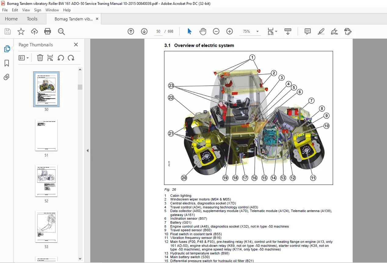
3 1 Overview of electric system 50
3 2 Overview of diesel engine 52
3 3 Overview of hydraulics 54
3 3 1 Pump overview 55
3 4 Overview of water sprinkling system 57
3 4 1 AD, ADO & AM 57
3 4 2 Pump overview 57
3 5 Overview of air conditioning system 60
3 6 Overview, AD drum 62
3 7 Overview, ADO drum 63
3 8 Information and safety stickers/decals on the machine 64
4 Electric systems 67
4 1 Overview of electric system 68
4 1 1 CAN BUS overview 75
4 2 Telemecanique switch 77
4 3 Magnetic coil plug 79
4 4 Deutsch plug, series DT and DTM 82
4 5 Servicing the battery, checking the main battery switch 86
4 5 1 Battery service 86
4 5 2 Checking the main battery switch 87
4 6 Starting the engine with jump leads 88
4 7 Asphalt temperature sensor, B106 90
4 8 Acceleration transducer, B84 & B85 91
4 9 Switching on the pressure sprinkler system 93
4 10 Data collector, A80 95
4 11 Differential pressure switch for hydraulic oil filter, B21 101
4 12 Air filter vacuum switch, B03 102
4 13 Sensor, water in fuel filter, B124 103
4 14 Float switch in coolant compensation tank, B55 104
4 15 Oil pressure switch, B06 105
4 16 Coolant temperature switch, B53 106
4 17 Removing and assembling the coolant temperature switch 107
4 18 Boost fuel solenoid valve 108
4 19 Engine solenoid to shut down the engine, Y58 109
4 20 Electric throttle control, Y120 110
4 21 Heating flange on engine 113
4 22 Checking the heating flange control 115
4 23 Charge control lamp 116
4 24 Fuse assignment 117
4 24 1 Notes on safety 117
4 24 2 Central electrics 117
4 24 3 Main fuses 118
4 24 4 Fuse, cabin 119
4 24 5 Fuses ROPS 120
4 25 Power board 121
4 26 Operator’s stand 125
4 26 1 Instrument cluster 127
4 27 Electric system, old version 130
4 27 1 CAN BUS overview 133
4 27 2 Switching on the pressure sprinkler system 134
4 27 3 Level sensor in diesel tank, R03 136
4 27 4 Immersion pipe sensor in water tank, R14 137
4 27 5 Float switch in water tank, B33 138
4 27 6 Float switch in coolant compensation tank, B55 139
4 27 7 Differential pressure switch for hydraulic oil filter, B21 140
4 27 8 Air filter vacuum switch, B03 141
4 27 9 Sensor, water in fuel filter, B124 142
4 27 10 Oil pressure switch, B06 143
4 27 11 Coolant temperature switch, B53 144
4 27 12 Heating flange on engine 145
4 27 13 Checking the heating flange control 147
4 27 14 Charge control lamp 148
4 27 15 Operator’s stand 150
4 27 15 1 Instrument cluster 151
5 Diesel engine 155
5 1 Overview of diesel engine 156
5 2 Service side 158
5 3 Starter side 159
5 4 Lubrication oil circuit 160
5 5 Coolant circuit 162
5 6 Replacing the thermostat 164
5 7 Fuel supply 166
5 8 Injection system 168
5 9 Injection pump replacement during service 170
5 9 1 Disassembling the injection pump 170
5 9 2 Determining the start of injection 172
5 9 3 Installing the injection pump 175
5 10 Injection valve replacement during service 180
5 11 Checking / repairing injection valves 183
5 12 Inspection and maintenance work 189
5 12 1 Checking the engine oil level 189
5 12 2 Change engine oil and oil filter cartridge 189
5 12 3 Check the coolant level 191
5 12 4 Check the anti-freeze concentration and the condition of the coolant 192
5 12 5 Change the coolant 192
5 12 6 Cleaning the radiator module 194
5 12 7 Replacing the fuel filter, bleeding the fuel system 195
5 12 7 1 Preliminary remarks 195
5 12 7 2 Replacing the fuel filter and the fuel pre-cleaner 196
5 12 7 3 Bleed the fuel system 198
5 12 8 Checking, cleaning the water separator 199
5 12 9 Service the belt drive 199
5 12 9 1 Checking the condition of the V-belt 200
5 12 9 2 Checking the V-belt tension 200
5 12 9 3 Tensioning the generator V-belt 201
5 12 9 4 Tensioning the fuel pump V-belt 202
5 12 9 5 Tensioning the air conditioning compressor V-belt 202
5 12 9 6 Replacing the V-belt 203
5 12 10 Air filter maintenance 204
5 12 10 1 Replace the safety element 206
5 12 11 Adjusting the valve clearance 206
5 12 12 Checking the compression 208
6 Hydraulic system 211
6 1 Overview of hydraulics 212
6 1 1 Pump overview 213
6 2 Open and closed hydraulic circuit 215
6 3 Hydraulic units 217
6 3 1 Travel pump, A4VG71 EP 217
6 3 1 1 Variable displacement pumps, A4VG28EP to 180EP 217
6 3 2 Vibration pump, A10VG28 EP 222
6 3 2 1 Variable displacement pump, A10VG28/45 EP 222
6 3 3 Swash plate principle, pump 227
6 3 4 Drum drive motor 229
6 3 4 1 Functional principle radial piston motors, MS/MSE 229
6 3 5 Vibration motor 231
6 3 5 1 Vibration motor A10FE/FM 231
6 3 6 External gear pumps 233
6 3 7 Outer gear motors non-reversible 235
6 3 8 Steering valve 236
6 4 Charge circuit and fan circuit 238
6 5 Travel circuit 240
6 6 Vibration circuit 245
6 7 Steering and crabwalk 253
6 8 Edge cutter 257
6 9 Inspection and maintenance work 259
6 9 1 Check the hydraulic lines 259
6 9 2 Checking the hydraulic oil level 259
6 9 3 Changing the hydraulic oil 260
6 9 4 Replacing the hydraulic oil filter 262
6 10 Tests and adjustments 265
6 10 1 Pump overview 265
6 10 2 Activate service mode 266
6 10 3 Driving against the closed brake 268
6 10 4 Pressure tests in the travel circuit 270
6 10 5 Checking / adjusting the neutral positions of the travel pump 272
6 10 6 Checking the setting of the high pressure relief valves in the travel circuit 275
6 10 7 Pressure tests in the front vibration circuit 277
6 10 8 Pressure tests in the rear vibration circuit 278
6 10 9 Checking the high pressure relief valves in the front vibration circuit 280
6 10 10 Checking the high pressure relief valves in the rear vibration circuit 282
6 11 Flushing and bleeding 285
6 11 1 Flushing – general 285
6 11 2 Flushing schematic for front drum drive 288
6 11 3 Flushing the front drum drive 289
6 11 4 Flushing schematic for rear drum drive system 293
6 11 5 Flushing the rear drum drive 294
6 11 6 Flushing schematic for front vibration drive 299
6 11 7 Flushing the front vibration circuit 300
6 11 8 Flushing schematic for rear vibration circuit 305
6 11 9 Flushing the rear vibration circuit 306
6 11 10 Bleeding the travel circuit 310
6 11 11 Bleeding the vibration circuit 312
7 Water spraying system 315
7 1 Overview of water sprinkling system 316
7 1 1 AD, ADO & AM 316
7 1 2 Pump overview 316
7 2 Inspection and maintenance work 319
7 2 1 Checking the water level, topping up 319
7 2 2 Cleaning water tank and water filter 320
7 2 3 Water spraying system, maintenance in case of frost 321
8 Air conditioning 327
8 1 Overview of air conditioning system 328
8 2 Physical principles 330
8 3 Refrigerant R134a 333
8 4 Compressor oil / refrigeration oil 336
8 5 Working principle of the air conditioning system 339
8 6 Monitoring devices 340
8 7 Description of components 341
8 8 Compressor 347
8 9 Emptying in case of repair 349
8 10 Drying and evacuation 350
8 11 Filling instructions 351
8 12 Steam table for R134a 356
8 13 Inspection and maintenance work 360
8 13 1 Checking the compressor oil level / refrigeration oil level 360
8 13 2 Service the air conditioning 360
8 13 2 1 Air conditioning function test 360
8 13 2 2 Checking the condition of the drier/collector unit 360
8 13 3 Cleaning the circulation air filter for the heating 362
8 13 4 Changing the fresh air filter in the cabin 362
9 Drum 365
9 1 Overview, AD drum 367
9 2 Overview, ADO drum 368
9 3 Inspection and maintenance work 369
9 3 1 Checking, adjusting the scrapers 369
9 3 2 Checking the oil level in the front exciter housing 369
9 3 3 Change the oil in the front exciter housing 370
9 3 4 Rear exciter housing, check for leaks 371
9 3 5 Change the oil in the rear exciter housing 371
9 3 6 Checking, tensioning the toothed belt for the rear drum 373
10 Troubleshooting 379
10 1 Preliminary remarks 380
10 2 What to do in events of emergency 381
10 2 1 Actuate the emergency stop switch 381
10 2 2 Disconnecting the battery 381
10 2 3 Towing the machine 381
10 2 4 After towing 384
10 3 Troubleshooting, electrical systems 386
10 3 1 Preliminary remarks 386
10 3 2 Starting the engine with jump leads 386
10 3 3 Checking the main battery switch 387
10 3 4 Fuse assignment 387
10 3 4 1 Notes on safety 387
10 3 4 2 Central electrics 388
10 3 4 3 Main fuses 389
10 3 4 4 Fuse, cabin 390
10 3 4 5 Fuses ROPS 391
10 3 5 Understanding electric circuit diagrams 391
10 3 5 1 Electric circuit diagrams 391
10 3 5 2 Circuit symbols in E-Plan 399
10 3 5 3 Identification of switch blocks 403
10 3 6 Metrology 404
10 3 7 ESX, checking the electric power supply 408
10 3 8 Diagnostics concept 416
10 3 9 Machine control, ESX 418
10 4 Trouble shooting, diesel engine 518
10 4 1 Starting the engine with jump leads 518
10 4 2 Fault – Cause – Remedy 519
10 5 Trouble shooting, hydraulics 521
10 5 1 Insufficient hydraulic power 521
10 5 2 Trouble shooting axial piston pumps 524
10 5 3 Trouble shooting axial piston motors 526
10 6 Trouble shooting, air conditioning system 528
10 6 1 Trouble shooting in refrigerant circuit, basic principles 528
10 6 2 Trouble shooting procedure 535
10 6 3 Leak test 544
10 6 4 Checking the magnetic clutch 545
11 Special tools 547
11 1 Special tools, electrics 548
11 2 Special tools, hydraulic system 549
11 2 1 Special tools, tests and adjustments 549
11 2 2 Special tools for flushing 551
11 3 Special tools for drum 556
11 3 1 ADO drum 556
11 4 List of special tools 558
Appendix 559
A Circuit diagrams 561
A A Hydraulic diagram 921 125 11a 561
A B Wiring diagram 282 563
A C Wiring diagram 337 624
Contact us: [email protected]
PLEASE NOTE:
- This is the SAME manual used by the dealers to troubleshoot any faults in your vehicle. This can be yours in 2 minutes after the payment is made.
- Contact us at [email protected] should you have any queries before your purchase or that you need any other service / repair / parts operators manual.
S.V