BOMAG BW 177 D-3 / DH-3 / PDH-3 BW 178 DH-3 / PDH-3 Operating instructions Maintenance instructions Manual – PDF DOWNLOAD
Original price was: $78.00.$25.95Current price is: $25.95.
BOMAG BW 177 D-3 / DH-3 / PDH-3 BW 178 DH-3 / PDH-3 Operating instructions Maintenance instructions Manual – PDF DOWNLOAD
Description
BOMAG BW 177 D-3 / DH-3 / PDH-3 BW 178 DH-3 / PDH-3 Operating instructions Maintenance instructions Manual – PDF DOWNLOAD
DESCRIPTION:
BOMAG BW 177 D-3 / DH-3 / PDH-3 BW 178 DH-3 / PDH-3 Operating instructions Maintenance instructions Manual – PDF DOWNLOAD
Foreword
Foreword BOMAG machines are products from the wide range of BOMAG compaction equipment. BOMAG’s vast experience, together with the most up-to-date production and testing methods, including service life tests of all important components and highest quality demands, guarantee maximum reliability of your machine
- These instructions comprise: l Safety regulations l Operating instructions l Maintenance instructions l Trouble shooting Using these instructions will l help you to get to know the machine.
- l avoid malfunctions caused by unexpert operation. Compliance with the maintenance instructions will l increase the reliability of your machine on the site, l increase the service life of the machine, l reduce repair costs and downtimes.
- BOMAG shall not assume liability for safe functioning of the machine l if it is handled in a way which does not comply with the usual modes of use, l if it is used for purposes other than those mentioned in the instructions. No warranty claims can
- be lodged for damage resulting from l operating errors, l insufficient maintenance and l wrong fuels and lubricants
Please note
! This manual has been written for the operator and the service personnel at the site. Keep this manual always close at hand, e.g. in the tool compartment of the machine or in the container provided
You should only operate the machine if you are fully familiar with the contents of these instructions. You must also observe all applicable safety regulations. Please observe also the guidelines of the Civil Engineering Liability Association “Safety Regulations for the Operation of Road Rollers and Soil Compactors” and the applicable accident prevention instructions.
For your own safety you should only use BOMAG-spare parts.
- We reserve the right for technical modifications without prior notification. These operating andmaintenance instructions are also available in other languages. A spare part catalogue can be obtained from your BOMAG dealer when giving him the
- serial number of your machine. Information about the correct use of our machines in earth work and for asphalt applications can be obtained from your BOMAG dealer. The above points do not constitute an extension of the warranty and
- liability conditions specified in the general terms of business of BOMAG. We wish you much success with your BOMAG machines.
TABLE OF CONTENTS:
BOMAG BW 177 D-3 / DH-3 / PDH-3 BW 178 DH-3 / PDH-3 Operating instructions Maintenance instructions Manual – PDF DOWNLOAD
BW 177 D-3 / DH-3 / PDH-3 1
BW 178 DH-3 / PDH-3 1
S/N 101 581 06 > S/N 101 581 07 > 1
S/N 101 581 08 > S/N 101 581 16 > 1
S/N 101 581 17 > 1
Single drum roller 1
BOMAG machines are products from the wide range of BOMAG compaction equipment 3
BOMAG’s vast experience, together with the most up-to-date production and testing methods, includ 3
These instructions comprise: 3
Using these instructions will 3
Compliance with the maintenance instructions will 3
BOMAG shall not assume liability for safe functioning of the machine 3
No warranty claims can be lodged for damage resulting from 3
Please note! 3
For your own safety you should only use BOMAG-spare parts 3
We reserve the right for technical modifications without prior notification 3
Please fill in 4
Fig 1 4
Fig 2 4
Fig 3 4
1 Technical Data 7
Fig 4 8
BW 177 D-3 8
BW 177 D-3 8
Weights 8
Travel characteristics 8
Engine 8
Brakes 9
Steering 9
Vibration 9
Tires 9
Tank contents 9
Fig 5 10
BW 177 DH-3 10
BW 177 PDH-3 10
BW 177 DH-3 10
BW 177 PDH-3 10
Weights 10
Travel characteristics 10
Engine 10
Brakes 11
Steering 11
Vibration 11
Tires 11
Tank contents 11
Fig 6 12
BW 178 DH-3 12
BW 178 PDH-3 12
BW 178 DH-3 12
BW 178 PDH-3 12
Weights 12
Travel characteristics 12
Engine 12
Brakes 13
Steering 13
Vibration 13
Tires 13
Tank contents 13
The following noise and vibration data acc to 14
– EC Machine Regulation edition (98/37/EC) and 14
– Noise Emission Regulation 2000/14/EC 14
were determined at nominal speed of the drive engine and with vibration running The machine was 14
During operation these values may vary because of the existing operating conditions 14
Noise value 14
sound pressure level at the work place of the operator (with cabin): 14
guaranteed sound capacity level of the machine: 14
Vibration value 14
Vibration of the entire boy (driver’s seat) 14
Hand-arm vibration values 14
2 Safety regulations 15
General 16
This BOMAG machine is built in accordance with the latest technical standard and the valid techni 16
Each person involved in operation, maintenance and repair of the machine must therefore read and 16
Intended use 16
Unintended use 16
Who is allowed to work with the machine? 16
Conversions and alterations to the machine 16
Safety notes in the operating and maintenance instructions: 16
Information and safety stickers/decals on the machine 17
Loading the machine 17
Towing the machine 17
Checking the roll-over protection structure (ROPS) 17
Starting the machine 17
Before starting 17
Starting 18
Starting with jump leads 18
Starting in closed rooms 18
Driving the machine 18
Persons in the danger area 18
Driving 18
Driving on gradients and slopes 19
Behaviour in traffic 19
Check the effect of vibration 19
Parking the machine 19
Parking on gradients or slopes 19
Filling the fuel tank 19
Fire protection measures 19
Maintenance work 19
Working on hydraulic lines 19
Changing of hydraulic hoses 20
Working on the engine 20
Working in the electric system 20
Working on the battery 20
Working on the fuel system 20
Working on wheels and tires 21
Cleaning 21
After maintenance work 21
Repair 21
Test 21
3 Indicators and Controls 23
31 General notes 24
32 Description of indicators and control elements 24
Fig 7 24
No 1 = Fuses in electric installation box 24
Fig 8 25
No 2 = Operating hour meter 25
Fig 9 25
No 3 = Fuel gauge 25
Fig 10 25
No 4 = Push button for warning horn 25
Fig 11 25
No 5 = Rotary switch, vibration 25
Fig 12 26
No 6 = Rotary switch speed ranges (D and PD machines) 26
Fig 13 26
No 7 = Rotary switch for speed ranges without ASC 26
Fig 14 26
No 8 = Rotary switch for speed ranges (DH and PDH machines with ASC) 26
Fig 15 26
No 9 = RPM-meter for vibrator shaft 26
Fig 16 27
No 10 = Emergency stop switch 27
Fig 17 27
No 11 = Rotary switch, lighting (StVZO) 27
Fig 18 27
No 12 = Rotary switch working lights 27
Fig 19 28
No 13 = Rotary switch for direction indicators left / right 28
Fig 20 28
No 14 = Fault monitoring board 28
The control and warning lights on the fault monitoring board flash: 28
Fig 21 29
No 15 = Push button for vibration 29
Fig 22 29
No 16 = Travel lever 29
Fig 23 29
No 17 = Throttle lever 29
No 18 = Locking plate for throttle lever 29
Fig 24 29
No 19 = Ignition switch 29
Fig 25 30
No 20 = Shut-off valve for cabin heater 30
Fig 26 30
No 21 = Rotary switch for hazard light system 30
Fig 27 30
No 22 = Tachometer 30
Fig 28 31
No 23 = Rpm-meter for diesel engine 31
Fig 29 31
No 24 = Main fuse for battery 31
Fig 30 31
No 25 = Pedal for dozer blade (BW 177 PDH-3) 31
Fig 31 31
No 26 = Fuse box, cabin 31
Fig 32 32
No 27 = Switches in cabin 32
Fig 33 32
No 28 = Inside light 32
Fig 34 32
No 29 = Fresh air intake slide 32
Fig 35 33
No 30 = Rotary switch for fan 33
Fig 36 33
No 31 = Rotary switch, air conditioning thermostat (air blowing temperature) 33
Fig 37 33
No 32 = Omega-meter 33
Omega value 33
4 Operation 35
41 General notes 36
42 Tests before starting to operate 36
Check: 36
43 Starting the engine 37
Fig 38 37
Fig 39 37
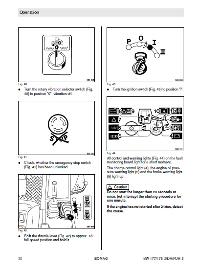
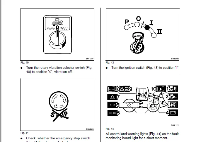
Fig 40 38
Fig 41 38
Fig 42 38
Fig 43 38
Fig 44 38
Fig 45 39
44 Starting with jump leads 39
Fig 46 39
45 Driving the machine 40
Fig 47 40
Fig 48 40
Fig 49 40
Fig 50 40
Fig 51 41
Fig 52 41
Important notes on travel operation 41
46 Emergency exit 42
47 Operating the parking brake, stopping the machine 42
Fig 53 42
48 Shutting the engine down 43
Fig 54 43
Fig 55 43
Fig 56 43
49 Switching the vibration on and off 44
Fig 57 44
Selecting the vibration 44
Fig 58 44
Switching the vibration on 44
Fig 59 44
Fig 60 45
Switching the vibration off 45
410 Adjusting the steering wheel 45
Fig 61 45
411 Adjusting the seat 46
Fig 62 46
Fig 63 46
412 Operating the hood 46
Fig 64 46
Fig 65 46
413 Towing in case of an engine failure 47
All machines 47
Fig 66 47
Fig 67 47
D and PD machines 47
Fig 68 47
Additionally on DH and PDH machines 48
Fig 69 48
After towing 48
Fig 70 48
Fig 71 48
414 Transport 49
Fig 72 49
Fig 73 49
Fig 74 49
Weights: see technical data 49
5 Maintenance 51
51 General notes on maintenance 52
Notes on the fuel system 52
Notes on the engine performance 52
Notes on the hydraulic system 52
Notes on the cooling system 53
52 Fuels and lubricants 53
Engine oil 53
Oil viscosity 53
Fig 75 53
Oil quality 53
Permitted API-oils 54
Permitted CCMC-oils 54
Lubrication oil change intervals 54
Fuels 54
Quality 54
Winter fuel 54
Hydraulic oil 54
Biodegradable hydraulic oil 54
Oil for drive axle 54
Lubrication grease 54
Coolant 54
Specification for cooling system protection agents 55
Anti-freeze agent concentrations 55
53 Table of fuels and lubricants 56
Assembly 56
Fuel or lubricant 56
Quantity approx 56
Summer 56
Winter 56
54 Running-in instructions 57
When taking new machines into operation or when starting up overhauled engines, the following mai 57
After 50 operating hours 57
After 500 operating hours 57
After 1000 operating hours 57
55 Maintenance chart 58
With all maintenance intervals perform also the work for shorter preceding service intervals 58
No 58
Designation 58
Note 58
Every 10 operating hours 58
Check the dust separator on the oil bath air filter 58
Every 50 operating hours 58
Every 250 operating hours 58
Every 500 operating hours 58
Every 1000 operating hours 59
Every 2000 operating hours 59
As required 59
56 Checking the engine oil level 60
Fig 76 60
For quality and quantity of oil refer to the table of fuels and lubricants 60
57 Checking, cleaning the water separator 60
Fig 77 60
58 Checking, cleaning the fuel filter water separator 61
Fig 78 61
59 Checking, cleaning the water separator 61
Fig 79 61
510 Checking the fuel level 62
Fig 80 62
Fig 81 62
For quality of fuel refer to the table of fuels and lubricants 62
511 Checking the coolant level 63
Fig 82 63
For quality of coolant refer to paragraph 52, fuels and lubricants 63
512 Checking the hydraulic oil level 63
Fig 83 63
Normal level 63
Minimum level 63
For quality and quantity of oil refer to the table of fuels and lubricants 63
513 Checking the V-belt 64
Fig 84 64
514 Checking the dust separator on the oil bath air filter 64
Fig 85 64
515 Cleaning the air conditioning condenser 65
Fig 86 65
Fig 87 65
516 Checking the tire pressure 66
Fig 88 66
Nominal value see “technical data” 66
517 Adjusting the scrapers 66
smooth drum only 66
Fig 89 66
padfoot drum only 66
Fig 90 66
518 Changing engine oil and oil filter cartridge 68
Fig 91 68
Fig 92 68
Fig 93 68
Fig 94 69
Fig 95 69
For quality and quantity of oil refer to the table of fuels and lubricants 69
Fig 96 69
519 Cleaning the cooling fins on engine and hydraulic oil cooler 70
Cleaning with compressed air 70
Fig 97 70
Cleaning with cold cleansing agent 70
520 Checking the oil level in the drive axle 71
Fig 98 71
For quality of oil refer to the table of fuels and lubricants 71
521 Checking the oil level in the left/right hand planetary drives 71
Fig 99 71
For quality of oil refer to the table of fuels and lubricants 71
522 Checking the oil level in the vibration bearing 72
Fig 100 72
For quality of oil refer to the table of fuels and lubricants 72
523 Check the oil level in the drum drive gear 72
Fig 101 72
For quality of oil refer to the table of fuels and lubricants 72
524 Service the air conditioning 73
Cleaning the condenser 73
Fig 102 73
Fig 103 73
Checking the refrigerant level 73
Fig 104 73
Fig 105 74
Fig 106 74
Fig 107 74
Checking the moisture level of the drying agent 74
Fig 108 74
Checking the condition of the drier/collector unit 75
Fig 109 75
525 Servicing the battery 76
Fig 110 76
Fig 111 76
526 Draining the sludge from the fuel tank 77
Fig 112 77
527 Changing the fuel filter cartridges 77
Fig 113 77
Fig 114 78
Fig 115 78
Manual bleeding 78
528 Changing the fuel pre-filter cartridge 79
Fig 116 79
Fig 117 79
529 Checking V-belt tension, idler pulley and blower hub 80
Fig 118 80
Fig 119 80
Fig 120 80
Fig 121 80
Fig 122 80
Nominal value: 81
530 Changing the oil in the drive axle 82
Fig 123 82
Fig 124 82
For quality and quantity of oil refer to the table of fuels and lubricants 82
531 Changing the oil in the planetary drive 83
Fig 125 83
Fig 126 83
For quality and quantity of oil refer to the table of fuels and lubricants 83
532 Changing the oil in the drum drive gear 84
Fig 127 84
Fig 128 84
For quality and quantity of oil refer to the table of fuels and lubricants 84
533 Changing the oil in the vibration bearing 85
Fig 129 85
Fig 130 85
For quality and quantity of oil refer to the table of fuels and lubricants 85
534 Checking the fastening elements on the engine 86
Fig 131 86
535 Tightening the fastening of the axle on the frame 86
Fig 132 86
536 Tightening the wheel nuts 87
Fig 133 87
Tightening torques 550 Nm (405 ft-lb) (M22x1,5) 87
537 Checking the ROPS 87
Fig 134 87
538 Cleaning the oil bath air filter 88
Fig 135 88
539 Checking, adjusting the valve clearance 89
Fig 136 89
Fig 137 89
Fig 138 89
Fig 139 89
Fig 140 90
Nominal value: 90
Fig 141 90
Fig 142 90
540 Changing the hydraulic oil and the breather filter 91
Fig 143 91
Fig 144 91
Nominal value: 91
For quality and quantity of oil refer to the table of fuels and lubricants 92
541 Changing the hydraulic oil filter 92
Fig 145 92
542 Change the coolant 93
Fig 146 93
Fig 147 93
Fig 148 94
For quality of coolant refer to the chapter 52, fuels and lubricants 94
543 Checking, cleaning, changing the combustion air filter 95
Fig 149 95
Fig 150 95
Fig 151 95
Fig 152 96
Fig 153 96
Fig 154 96
Fig 155 97
Dry cleaning of the main filter element 97
Fig 156 97
Changing the safety filter element 97
Fig 157 98
544 Bleeding the fuel system 98
Bleeding low pressure fuel lines and fuel filter 98
Fig 158 98
Bleeding the injection pump 98
Fig 159 98
Fig 160 99
Bleeding the high pressure fuel lines 99
Fig 161 99
545 Adjusting the parking brake 99
Fig 162 99
Fig 163 99
Fig 164100
546 Changing the tires100
Fig 165100
547 Checking the fresh air filter for the cabin101
Fig 166101
548 Tightening torques101
Fig 167101
549 Engine conservation102
Anti-corrosion oils are those that comply with the specification MIL-L-21260 B or TL 9150- 037/2 102
A machine with a conserved engine must be marked by attaching a clearly visible warning tag102
6 Trouble shooting103
61 General notes104
The following work must only be carried out by qualified and trained personnel or by the sales se104
Please observe strictly the safety regulations in chapter 2 of these operating and maintenance in104
62 Engine105
Faults105
Possible cause105
Remedy105
IMAGES PREVIEW OF THE MANUAL:
BOMAG BW 177 D-3 / DH-3 / PDH-3 BW 178 DH-3 / PDH-3 OPERATING INSTRUCTIONS MAINTENANCE INSTRUCTIONS MANUAL – PDF DOWNLOAD:
PLEASE NOTE:
- This is the SAME exact manual used by your dealers to fix your vehicle.
- The same can be yours in the next 2-3 mins as you will be directed to the download page immediately after paying for the manual.
- Any queries / doubts regarding your purchase, please feel free to contact [email protected]
S.M