BOMAG BW219DH-5 Service Manual PDF Download
Original price was: $200.00.$34.95Current price is: $34.95.
Download the BOMAG BW219DH-5 service manual PDF for single drum roller repair on models BW219DH-5, BW219PDH-5, BW226DH-5, BW226PDH-5. This BOMAG single drum roller troubleshooting guide includes hydraulic systems, electrical diagrams, maintenance schedules, and assembly instructions in the BW219DH-5 repair manual. Essential for technicians performing BOMAG roller maintenance manual tasks and BW219DH-5 schematic diagrams PDF analysis.
Description
BOMAG BW219DH-5 Service Manual PDF Download
Description
The BOMAG BW219DH-5 Service Manual PDF Download is a detailed technical resource for servicing BOMAG single drum rollers, covering models BW219DH-5, BW219PDH-5, BW226DH-5, and BW226PDH-5. This BOMAG single drum roller troubleshooting guide offers in-depth guidance on safety, technical data, hydraulic and electrical systems, machine assemblies, troubleshooting, and special tools, making it a crucial BW219DH-5 repair manual for construction equipment professionals.
File Details:
- Manual Name: Service Manual for BW 219 DH-5 / BW 219 PDH-5 / BW 226 DH-5 / BW 226 PDH-5
- Models Covered: BW219DH-5, BW219PDH-5, BW226DH-5, BW226PDH-5
- Year: 2018
- Manual PDF Quality: High-quality scanned document
- No. of Pages: 978
The manual is structured with comprehensive sections for efficient navigation. Below is the neatly categorized Table of Contents extracted from the manual:
- 1 General Information (Page 9)
- 1.1 Introduction (Page 10)
- 1.2 Concerning Your Safety (Page 12)
- 1.2.1 Basic Prerequisites (Page 12)
- 1.2.2 Definition of Responsible Persons (Page 15)
- 1.2.3 Fundamentals for Safe Operation (Page 16)
- 1.2.4 Handling Fuels and Lubricants (Page 17)
- 1.2.5 Load/Transport the Machine (Page 23)
- 1.2.6 Start-up Procedure (Page 24)
- 1.2.7 Driving the Machine; Working Operation (Page 25)
- 1.2.8 Refuelling (Page 27)
- 1.2.9 Emergency Procedures (Page 28)
- 1.2.10 Maintenance Work (Page 29)
- 1.2.11 Repair (Page 31)
- 1.2.12 Signage (Page 31)
- 1.3 Maintenance and Repair (Page 40)
- 1.3.1 Notes on Repair (Page 40)
- 1.3.2 Preliminary Remarks and Safety Notes (Page 56)
- 1.3.3 Preparations / Concluding Work (Page 57)
- 1.3.4 Parking the Machine in Secured Condition (Page 59)
- 2 Technical Data (Page 61)
- 2.1 Technical Data, BW 219 DH-5 (Page 62)
- 2.2 Technical Data, BW 219 PDH-5 (Page 66)
- 2.3 Technical Data, BW 226 DH-5 (Page 70)
- 2.4 Technical Data, BW 226 PDH-5 (Page 73)
- 2.5 Additional Technical Data (Page 77)
- 2.6 Terms and Basis of Calculation (Page 80)
- 2.7 Fuels and Lubricants (Page 81)
- 2.7.1 Engine Oil (Page 81)
- 2.7.2 Fuel (Page 82)
- 2.7.3 Coolant (Page 83)
- 2.7.4 Hydraulic Oil (Page 86)
- 2.7.5 Gear Oil SAE 75W-90 (Page 86)
- 2.7.6 Gear Oil SAE 80W-140 (Page 86)
- 2.8 List of Fuels and Lubricants (Page 88)
- 3 Overview of Machine (Page 91)
- 3.1 General Information (Page 92)
- 3.1.1 Terrameter (Page 95)
- 3.1.2 Economizer (Page 96)
- 3.1.3 BCM 05 (Page 97)
- 3.1.4 BCM Start (Page 99)
- 3.1.5 BCM Net (Page 100)
- 3.1.6 BOMAG Telematic (Page 101)
- 3.2 Electric Systems (Page 103)
- 3.3 Hydraulic System (Page 105)
- 3.4 Machine Assemblies (Page 106)
- 3.4.1 Diesel Engine (Page 106)
- 3.4.2 Drum (Page 107)
- 3.4.3 Air Conditioning (Page 108)
- 3.4.4 Auxiliary Heating, AIRTRONIC (Page 109)
- 3.1 General Information (Page 92)
- 4 Electric Systems (Page 111)
- 4.1 Basic Principles (Page 113)
- 4.1.1 Measuring Method (Page 113)
- 4.1.2 Understanding Electric Circuit Diagrams (Page 117)
- 4.1.3 Telemecanique Switch (Page 130)
- 4.1.4 Deutsch Plug, Series DT and DTM (Page 132)
- 4.2 Overview of Electric System (Page 136)
- 4.2.1 Central Electrics (Page 138)
- 4.2.2 Operator’s Stand (Page 140)
- 4.2.3 Wiring (Page 141)
- 4.2.4 CAN BUS Overview (Page 159)
- 4.2.5 Table of Fuels and Lubricants (Page 161)
- 4.3 Starting the Engine with Jump Leads (Page 169)
- 4.4 Fuse Assignment (Page 170)
- 4.4.1 Notes on Safety (Page 170)
- 4.4.2 Central Electrics (Page 170)
- 4.4.3 Main Fuses (Page 171)
- 4.4.4 Control Console Cabin (Page 172)
- 4.5 Central Electrics (Page 173)
- 4.6 Description of Electrical Components (Page 181)
- 4.6.1 Control Console Cabin (Page 181)
- 4.6.2 Acceleration Transducer, B62 & B171 (Page 184)
- 4.6.3 Differential Pressure Switch for Hydraulic Oil Filter, B21 (Page 185)
- 4.6.4 Air Filter Vacuum Switch, B03 (Page 185)
- 4.6.5 Sensor, Water in Fuel, B124 (Page 186)
- 4.6.6 Float Switch Coolant Tank, B55 (Page 186)
- 4.6.7 Level Sensor in Diesel Tank (R03) (Page 187)
- 4.6.8 Charge Control Light (Page 187)
- 4.6.9 Electric Module, A108 (Page 189)
- 4.7 Training of Electric System (Page 190)
- 4.7.1 Electrics Training Machine Control (Page 190)
- 4.8 Inspection and Maintenance Work (Page 299)
- 4.8.1 Maintenance Table (Page 299)
- 4.8.2 Every 500 Operating Hours (Page 299)
- 4.8.3 As Required (Page 300)
- 4.1 Basic Principles (Page 113)
- 5 Hydraulic System (Page 303)
- 5.1 Basic Principles (Page 305)
- 5.1.1 Open and Closed Hydraulic Circuit (Page 305)
- 5.1.2 Swash Plate Principle, Pump (Page 307)
- 5.1.3 Swash Plate Principle, Motor (Page 308)
- 5.1.4 External Gear Pumps (Page 309)
- 5.2 Overview of Hydraulics (Page 312)
- 5.3 Description of Hydraulic Components (Page 315)
- 5.3.1 Travel / Vibration Pump, H1 (Page 315)
- 5.3.2 Travel Motor, H1 (Page 319)
- 5.3.3 Vibration Motor A2FM (Page 321)
- 5.3.4 Steering Valve (Page 323)
- 5.4 Description of Hydraulic Circuits (Page 325)
- 5.4.1 Charge Circuit (Page 326)
- 5.4.2 Travel Circuit (Page 327)
- 5.4.3 Vibration Circuit (Page 336)
- 5.4.4 Steering Circuit (Page 343)
- 5.4.5 Bypass Flow Filter (Page 347)
- 5.5 Flushing and Bleeding (Page 349)
- 5.5.1 Flushing – General (Page 349)
- 5.5.2 Drum Drive (Page 352)
- 5.5.3 Axle Drive (Page 358)
- 5.5.4 Vibration Circuit (Page 364)
- 5.5.5 Bleeding the Travel Circuit (Page 369)
- 5.5.6 Bleeding the Vibration Circuit (Page 371)
- 5.6 Inspection and Maintenance Work (Page 373)
- 5.6.1 Maintenance Table (Page 373)
- 5.6.2 Checks Prior to Start Up (Page 373)
- 5.6.3 Every 500 Operating Hours (Page 374)
- 5.6.4 Every 1000 Operating Hours (Page 376)
- 5.6.5 Every 2000 Operating Hours (Page 377)
- 5.1 Basic Principles (Page 305)
- 6 Machine Assemblies (Page 379)
- 6.1 Diesel Engine (Page 381)
- 6.1.1 Overviews (Page 382)
- 6.1.2 Lubrication Oil Circuit TCD 4.1 / 6.1 (Page 389)
- 6.1.3 Coolant Circuit TCD 4.1 / 6.1 (Page 391)
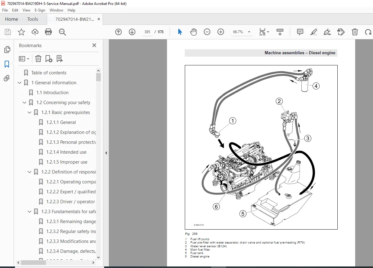
- 6.1.4 Common Rail System (CRS) (Page 392)
- 6.1.5 Wastegate Charge Pressure Controller (Page 399)
- 6.1.6 Exhaust Gas Recirculation (Page 401)
- 6.1.7 Engine Electrics (Page 402)
- 6.1.8 Inspection and Maintenance Work (Page 422)
- 6.2 Drum (Page 445)
- 6.2.1 Repair Overview for Drum (Page 445)
- 6.2.2 Dismantling the Drum (Page 449)
- 6.2.3 Dismantling and Assembling the Change-over Weight (Page 464)
- 6.2.4 Assembling the Drum (Page 467)
- 6.2.5 Changing the Rubber Buffers, Adjusting the Pretension (Page 490)
- 6.2.6 Smooth Drum Scraper; Installation and Removal (Page 495)
- 6.2.7 Pad Foot Scraper; Installation and Removal (Page 499)
- 6.2.8 Padfoot Shell; Installation and Removal (Page 503)
- 6.2.9 Inspection and Maintenance Work (Page 519)
- 6.3 Oscillating Articulated Joint (Page 525)
- 6.3.1 Overview (Page 525)
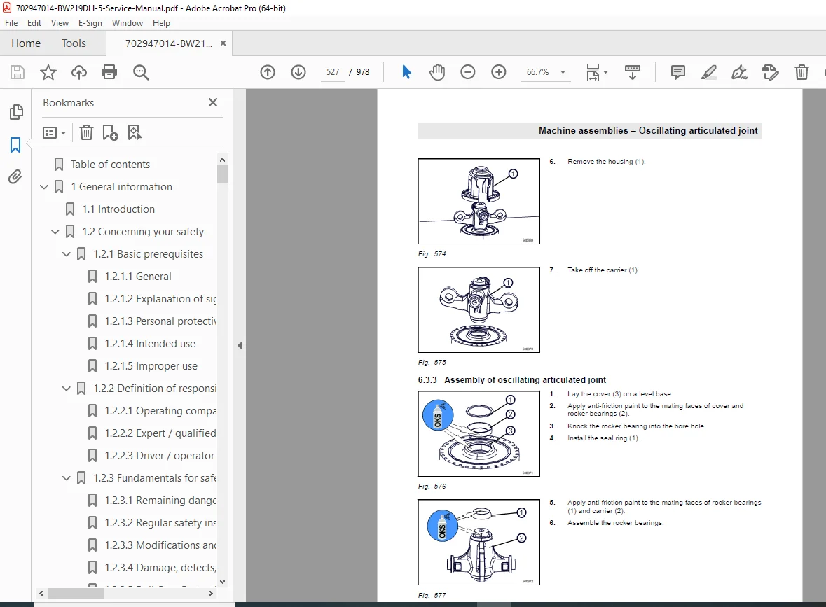
- 6.3.2 Dismantling the Oscillating Articulated Joint (Page 526)
- 6.3.3 Assembly of Oscillating Articulated Joint (Page 527)
- 6.4 Drive Axle (Page 531)
- 6.4.1 Drive Axle (Page 531)
- 6.4.2 Checks Prior to Start Up (Page 531)
- 6.4.3 Every 250 Operating Hours (Page 532)
- 6.4.4 Every 1000 Operating Hours (Page 534)
- 6.4.5 As Required (Page 538)
- 6.5 Air Conditioning (Page 540)
- 6.5.1 Overview of Air Conditioning System (Page 540)
- 6.5.2 Physical Principles (Page 542)
- 6.5.3 Refrigerant R134a (Page 544)
- 6.5.4 Compressor Oil / Refrigeration Oil (Page 546)
- 6.5.5 Working Principle of the Air Conditioning System (Page 548)
- 6.5.6 Monitoring Devices (Page 549)
- 6.5.7 Description of Components (Page 550)
- 6.5.8 Compressor (Page 556)
- 6.5.9 Emptying in Case of Repair (Page 557)
- 6.5.10 Drying and Evacuation (Page 558)
- 6.5.11 Filling Instructions (Page 559)
- 6.5.12 Steam Table for R134a (Page 562)
- 6.5.13 Inspection and Maintenance Work (Page 566)
- 6.6 Auxiliary Heating, AIRTRONIC (Page 574)
- 6.6.1 Overview (Page 574)
- 6.6.2 Inspection and Maintenance Work (Page 579)
- 6.7 Cabin Assembly (Page 580)
- 6.7.1 Safety (Page 580)
- 6.7.2 Preparations (Page 581)
- 6.7.3 Cabin Assembly (Page 582)
- 6.7.4 Final Function Tests and Checks (Page 587)
- 6.8 ROPS/FOPS Assembly (Page 589)
- 6.8.1 Safety (Page 589)
- 6.8.2 Preparations (Page 590)
- 6.8.3 ROPS/FOPS Assembly (Page 591)
- 6.8.4 Final Work (Page 595)
- 6.1 Diesel Engine (Page 381)
- 7 Troubleshooting (Page 597)
- 7.1 Preliminary Remarks (Page 598)
- 7.2 Emergency Procedures (Page 599)
- 7.2.1 Actuating the Emergency Stop Switch (Page 599)
- 7.2.2 Disconnecting the Battery (Page 599)
- 7.2.3 Emergency Exit (Page 599)
- 7.2.4 Towing the Machine (Page 600)
- 7.2.5 After Towing (Page 602)
- 7.3 Troubleshooting, Electrical Systems (Page 605)
- 7.3.1 Preliminary Remarks (Page 605)
- 7.3.2 Starting the Engine with Jump Leads (Page 608)
- 7.3.3 Servicing the Battery, Checking the Main Battery Isolation (Page 609)
- 7.3.4 Fuse Assignment (Page 610)
- 7.3.5 ESX, Checking the Electric Power Supply (Page 612)
- 7.3.6 Diagnostics Concept (Page 620)
- 7.4 Trouble Shooting, Diesel Engine (Page 623)
- 7.4.1 Starting the Engine with Jump Leads (Page 623)
- 7.4.2 Engine Malfunctions (Page 624)
- 7.4.3 Deutz DTC Fault Code List, EMR4 (Page 627)
- 7.5 Trouble Shooting, Hydraulics (Page 687)
- 7.5.1 Insufficient Hydraulic Power (Page 687)
- 7.5.2 Troubleshooting Axial Piston Pumps (Page 690)
- 7.5.3 Troubleshooting Axial Piston Motors (Page 692)
- 7.5.4 Troubleshooting Table for Hydraulic Components (Page 694)
- 7.6 Troubleshooting, Air Conditioning System (Page 702)
- 7.6.1 Trouble Shooting in Refrigerant Circuit, Basic Principles (Page 702)
- 7.6.2 Trouble Shooting Procedure (Page 708)
- 7.6.3 Leak Test (Page 717)
- 7.6.4 Checking the Magnetic Clutch (Page 718)
- 7.7 Troubleshooting, Auxiliary Heating (Page 720)
- 7.7.1 Control and Safety Elements (Page 722)
- 7.7.2 Trouble Shooting (Page 722)
- 7.7.3 Diagnostics with the Module Clock (Page 724)
- 7.7.4 Check the Fuel Supply (Page 728)
- 7.7.5 Circuit Diagram, AIRTRONIC D2/D4 (Page 730)
- 7.7.6 Fault Code, AIRTRONIC D2/D4 (Page 734)
- 8 Special Tools (Page 739)
- 8.1 Special Tools, Electrics (Page 740)
- 8.2 Special Tools, Hydraulic System (Page 741)
- 8.2.1 Special Tools, Tests and Adjustments (Page 741)
- 8.2.2 Special Tools for Flushing (Page 743)
- 8.3 Special Tools for Oscillating Articulated Joint (Page 744)
- 8.4 Special Tools, Drum (Page 746)
- 8.5 List of Special Tools (Page 748)
- 9 Index (Page 749)
- Appendix (Page 767)
- A Circuit Diagrams (Page 769)
- A.1 Circuit Diagram 354 (Page 769)
- A.2 Circuit Diagram 520 (Page 856)
- A.3 Hydraulic Diagram 479 (Page 952)
- A.4 Hydraulic Diagram 480 (Page 964)
- A Circuit Diagrams (Page 769)
This BW219DH-5 schematic diagrams PDF and BOMAG roller maintenance manual enable accurate diagnostics and repairs with diagrams and troubleshooting aids. No index beyond the main TOC is provided, but it includes an appendix with circuit and hydraulic diagrams.
Elevate your equipment servicing—download this BOMAG BW219DH-5 service manual PDF instantly for comprehensive guidance and reliable roller performance