Bomag MPH 122-2 Function.42 Wiring Diagram Manual EN_DE – PDF DOWNLOAD
$16.95
Bomag MPH 122-2 Function.42 Wiring Diagram Manual EN_DE – PDF DOWNLOAD
Description
Bomag MPH 122-2 Function.42 Wiring Diagram Manual EN_DE – PDF DOWNLOAD
FILE DETAILS:
Bomag MPH 122-2 Function.42 Wiring Diagram Manual EN_DE – PDF DOWNLOAD
Language : English_German
Pages : 58
Downloadable : Yes
File Type : PDF
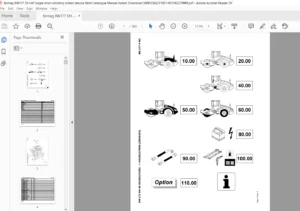
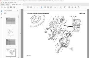
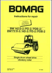
IMAGES PREVIEW OF THE MANUAL:
TABLE OF CONTENTS:
Bomag MPH 122-2 Function.42 Wiring Diagram Manual EN_DE – PDF DOWNLOAD
Page Tree 1
DOC1 1
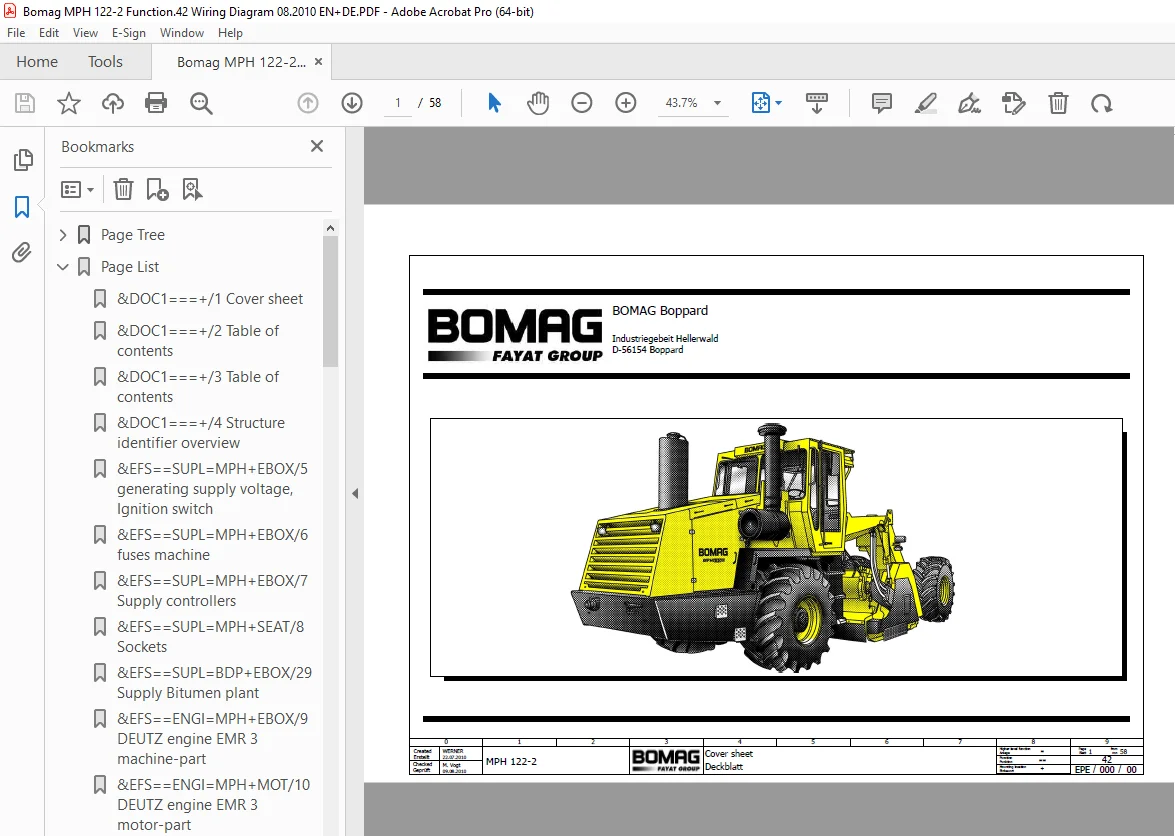
1 Cover sheet 1
2 Table of contents 2
3 Table of contents 3
4 Structure identifier overview 4
EFS 5
MPH 5
SUPL 5
EBOX 5
5 generating supply voltage, Ignition switch 5
6 fuses machine 6
7 Supply controllers 7
SEAT 8
8 Sockets 8
ENGI 10
EBOX 10
9 DEUTZ engine EMR 3 machine-part 10
MOT 11
10 DEUTZ engine EMR 3 motor-part 11
COM 12
EBOX 12
11 communication CAN1 / CAN2 12
DRIV 13
EBOX 13
12 Drive functions 1 13
13 Drive functions 2 14
STER 15
REFR 15
14 Steering rear Axle 15
MILL 16
EBOX 16
15 Milling functions 16
REFR 17
16 Rotor Hight Adjust and Flap 17
17 Cross-Slope and gear-box 18
VIB 19
REFR 19
18 Vibration Plates 19
DATA 20
EBOX 20
19 Bomag telematics 20
20 Indicators 1 21
SEAT 22
21 Indicators BAUSER 1 22
22 Indicators BAUSER 2 23
COMF 24
EBOX 24
23 air conditioning 24
CAB 25
24 KAMM cabin 25
ILUM 26
SEAT 26
25 Working lights 26
BDP 9
SUPL 9
EBOX 9
29 Supply Bitumen plant 9
WDP 27
WDOS 27
EBOX 27
26 Flow rate sensor with measuring transducer 27
27 dosing milling water 28
CDP 29
CEDI 29
EBOX 29
28 cement disperse functions 29
DOC2 30
30 Component-Listing 30
31 Component-Listing 31
32 Component-Listing 32
33 Component-Listing 33
34 Component-Listing 34
35 Component-Listing 35
36 Component-Listing 36
37 Component-Listing 37
38 Terminal diagram 38
39 Terminal diagram 39
40 Terminal diagram 40
41 Terminal diagram 41
42 Terminal diagram 42
43 Pin overview A66 43
44 Pin overview A66 44
45 Pin overview A83 45
46 Pin overview A78 46
47 Plug diagram 47
48 Plug diagram 48
49 Plug diagram 49
50 Plug diagram 50
51 Plug diagram 51
52 Plug diagram 52
53 Illustration X1 53
54 Illustration X1 54
55 Illustration X1 55
56 Illustration X1 56
57 Illustration X5 for DCD – Controller, Option 57
58 Assembly Plate overview 58
Page List 1
&DOC1===+/1 Cover sheet 1
&DOC1===+/2 Table of contents 2
&DOC1===+/3 Table of contents 3
&DOC1===+/4 Structure identifier overview 4
&EFS==SUPL=MPH+EBOX/5 generating supply voltage, Ignition switch 5
&EFS==SUPL=MPH+EBOX/6 fuses machine 6
&EFS==SUPL=MPH+EBOX/7 Supply controllers 7
&EFS==SUPL=MPH+SEAT/8 Sockets 8
&EFS==SUPL=BDP+EBOX/29 Supply Bitumen plant 9
&EFS==ENGI=MPH+EBOX/9 DEUTZ engine EMR 3 machine-part 10
&EFS==ENGI=MPH+MOT/10 DEUTZ engine EMR 3 motor-part 11
&EFS==COM=MPH+EBOX/11 communication CAN1 / CAN2 12
&EFS==DRIV=MPH+EBOX/12 Drive functions 1 13
&EFS==DRIV=MPH+EBOX/13 Drive functions 2 14
&EFS==STER=MPH+REFR/14 Steering rear Axle 15
&EFS==MILL=MPH+EBOX/15 Milling functions 16
&EFS==MILL=MPH+REFR/16 Rotor Hight Adjust and Flap 17
&EFS==MILL=MPH+REFR/17 Cross-Slope and gear-box 18
&EFS==VIB=MPH+REFR/18 Vibration Plates 19
&EFS==DATA=MPH+EBOX/19 Bomag telematics 20
&EFS==DATA=MPH+EBOX/20 Indicators 1 21
&EFS==DATA=MPH+SEAT/21 Indicators BAUSER 1 22
&EFS==DATA=MPH+SEAT/22 Indicators BAUSER 2 23
&EFS==COMF=MPH+EBOX/23 air conditioning 24
&EFS==COMF=MPH+CAB/24 KAMM cabin 25
&EFS==ILUM=MPH+SEAT/25 Working lights 26
&EFS==WDOS=WDP+EBOX/26 Flow rate sensor with measuring transducer 27
&EFS==WDOS=WDP+EBOX/27 dosing milling water 28
&EFS==CEDI=CDP+EBOX/28 cement disperse functions 29
&DOC2===+/30 Component-Listing 30
&DOC2===+/31 Component-Listing 31
&DOC2===+/32 Component-Listing 32
&DOC2===+/33 Component-Listing 33
&DOC2===+/34 Component-Listing 34
&DOC2===+/35 Component-Listing 35
&DOC2===+/36 Component-Listing 36
&DOC2===+/37 Component-Listing 37
&DOC2===+/38 Terminal diagram 38
&DOC2===+/39 Terminal diagram 39
&DOC2===+/40 Terminal diagram 40
&DOC2===+/41 Terminal diagram 41
&DOC2===+/42 Terminal diagram 42
&DOC2===+/43 Pin overview A66 43
&DOC2===+/44 Pin overview A66 44
&DOC2===+/45 Pin overview A83 45
&DOC2===+/46 Pin overview A78 46
&DOC2===+/47 Plug diagram 47
&DOC2===+/48 Plug diagram 48
&DOC2===+/49 Plug diagram 49
&DOC2===+/50 Plug diagram 50
&DOC2===+/51 Plug diagram 51
&DOC2===+/52 Plug diagram 52
&DOC2===+/53 Illustration X1 53
&DOC2===+/54 Illustration X1 54
&DOC2===+/55 Illustration X1 55
&DOC2===+/56 Illustration X1 56
&DOC2===+/57 Illustration X5 for DCD – Controller, Option 57
&DOC2===+/58 Assembly Plate overview 58
S.V 08/24