Bomag MPH 600 Tier 4i Function.154 Wiring Diagram Manual EN_DE PDF
$26.95
Bomag MPH 600 Tier 4i Function.154 Wiring Diagram Manual EN_DE – PDF DOWNLOAD
Description
Bomag MPH 600 Tier 4i Function.154 Wiring Diagram Manual EN_DE – PDF DOWNLOAD
FILE DETAILS:
Bomag MPH 600 Tier 4i Function.154 Wiring Diagram Manual EN_DE – PDF DOWNLOAD
Language : English_German
Pages : 109
Downloadable : Yes
File Type : PDF
IMAGES PREVIEW OF THE MANUAL:
TABLE OF CONTENTS:
Bomag MPH 600 Tier 4i Function.154 Wiring Diagram Manual EN_DE – PDF DOWNLOAD
Page tree 1
DOC1 Leading documentation 1
1 Cover sheet 1
2 Table of contents 2
3 Table of contents 3
4 Table of contents 4
5 Structure identifier overview 5
EFS Circuit diagram 6
MPH Basic machine 6
SUPL Supply 6
EBOX Central electric 6
6 generating supply voltage 6
7 fuses machine 7
8 Supply controllers 8
SEAT Seat console 9
9 Ignition switch 9
REFR Rear frame 10
10 Controller unit, Valves 10
ENGI Engine 11
EBOX Central electric 11
11 Engine – Deutz Tier4i, machine 11
12 Engine – Deutz Tier4i, motor 12
13 Engine – Deutz Tier4i, motor 13
14 Engine – Deutz Tier 4i, SCR system 14
MOT Engine and attachment parts 15
15 Engine – Deutz Tier 4i, SCR system 15
REFR Rear frame 16
16 Engine and hydraulic oil cooler 16
COM Communication 17
EBOX Central electric 17
17 communication CAN1 / CAN2 17
18 communication CAN3 / serial 18
DRIV Drive functions 19
SEAT Seat console 19
19 security devices and engine speed adjustment 19
20 actuation drive functions 20
FRFR Front frame 21
21 sensors and valves drive 21
STER Steering functions 22
EBOX Central electric 22
22 Buckling-link steering 22
REFR Rear frame 23
23 rear axle steering 23
MILL Milling functions 24
SEAT Seat console 24
24 Adjustment front, rear and mixing gates 24
REFR Rear frame 25
25 sensors and valves Milling 25
26 Milling-Tool exchange 26
27 Sensors and valves / Rotor Hood 27
VIB Vibration functions 28
REFR Rear frame 28
28 Vibration Plates 28
DATA Data collector / signals 29
EBOX Central electric 29
29 Bomag telematics 29
30 signals gear-box monitoring and fuel level sensor 30
FRFR Front frame 31
31 signals data collector engine and hydraulic 31
COMF Comfort devices 32
REFR Rear frame 32
32 adjustment cabin 32
CAB Cabin and attachment parts 33
33 fuses cabin 33
34 Windscreen Wipers and Washers 34
35 mounting parts cabin 35
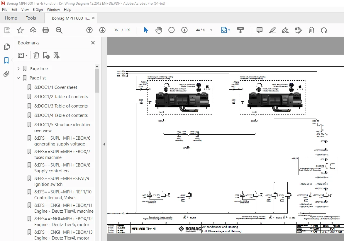
36 Air conditioner and Heating 36
37 Rear View Camera, Printer and Mirror adjustment 37
ILUM Lighting 38
SEAT Seat console 38
38 Working lights 38
WDP Water dosage plant (option) 39
WDOS Water dosing 39
EBOX Central electric 39
39 dosing milling water 39
WSPR Water spraying 40
HOD Hood 40
40 spray valves water 40
BDP Bitumen dosage plant (option) 41
BDOS Bitumen dosing 41
EBOX Central electric 41
41 voltage supply BOMAG 41
42 output signals dosage controller 42
43 input signals dosage controller 43
PUM Pump module (Breining) 44
44 flowmeter bitumen 44
BSPR Bitumen spraying 45
REFR Rear frame 45
45 spray valves bitumen 45
46 adaption valve modules BLM 2 and BLM 3 46
47 sensors and additional valves for spray module 47
48 combi-valves 1 10 48
49 combi-valves 11 21 49
PUM Pump module (Breining) 50
50 components pump module 50
RWT Reaction Water Tank (Breining) 51
51 heating and reaction water system 51
DOC2 Reports and drawings 52
52 Component-Listing 52
53 Component-Listing 53
54 Component-Listing 54
55 Component-Listing 55
56 Component-Listing 56
57 Component-Listing 57
58 Component-Listing 58
59 Component-Listing 59
60 Component-Listing 60
61 Component-Listing 61
62 Component-Listing 62
63 Component-Listing 63
64 Component-Listing 64
65 Component-Listing 65
66 Pin overview A66 66
67 Pin overview A66 67
68 Pin overview A80 68
69 Pin overview A81 69
70 Pin overview A145 70
71 Pin overview S55 71
72 Pin overview S71 72
73 Pin overview A03 73
74 Pin overview A104 74
75 Pin overview A104 75
76 Pin overview A83 76
77 Pin overview A83 77
78 Pin overview A98 78
79 Pin overview A104 79
80 Terminal diagram 80
81 Terminal diagram 81
82 Terminal diagram 82
83 Terminal diagram 83
84 Terminal diagram 84
85 Plug diagram 85
86 Plug diagram 86
87 Plug diagram 87
88 Plug diagram 88
89 Plug diagram 89
90 Plug diagram 90
91 Plug diagram 91
92 Plug diagram 92
93 Plug diagram 93
94 Plug diagram 94
95 Plug diagram 95
96 Plug diagram 96
97 Plug diagram 97
98 Plug diagram 98
99 Plug diagram 99
100 Plug diagram 100
101 Plug diagram 101
102 Illustrations terminal strips 102
103 Illustrations terminal strips 103
104 Illustrations terminal strips 104
105 Illustrations terminal strips 105
106 Illustrations terminal strips 106
107 Overview E-Box 107
108 Assembly Plate overview 108
109 system overview / modules bitumen plant 109
Page list 1
&DOC1/1 Cover sheet 1
&DOC1/2 Table of contents 2
&DOC1/3 Table of contents 3
&DOC1/4 Table of contents 4
&DOC1/5 Structure identifier overview 5
&EFS==SUPL=MPH+EBOX/6 generating supply voltage 6
&EFS==SUPL=MPH+EBOX/7 fuses machine 7
&EFS==SUPL=MPH+EBOX/8 Supply controllers 8
&EFS==SUPL=MPH+SEAT/9 Ignition switch 9
&EFS==SUPL=MPH+REFR/10 Controller unit, Valves 10
&EFS==ENGI=MPH+EBOX/11 Engine – Deutz Tier4i, machine 11
&EFS==ENGI=MPH+EBOX/12 Engine – Deutz Tier4i, motor 12
&EFS==ENGI=MPH+EBOX/13 Engine – Deutz Tier4i, motor 13
&EFS==ENGI=MPH+EBOX/14 Engine – Deutz Tier 4i, SCR system 14
&EFS==ENGI=MPH+MOT/15 Engine – Deutz Tier 4i, SCR system 15
&EFS==ENGI=MPH+REFR/16 Engine and hydraulic oil cooler 16
&EFS==COM=MPH+EBOX/17 communication CAN1 / CAN2 17
&EFS==COM=MPH+EBOX/18 communication CAN3 / serial 18
&EFS==DRIV=MPH+SEAT/19 security devices and engine speed adjustment 19
&EFS==DRIV=MPH+SEAT/20 actuation drive functions 20
&EFS==DRIV=MPH+FRFR/21 sensors and valves drive 21
&EFS==STER=MPH+EBOX/22 Buckling-link steering 22
&EFS==STER=MPH+REFR/23 rear axle steering 23
&EFS==MILL=MPH+SEAT/24 Adjustment front, rear and mixing gates 24
&EFS==MILL=MPH+REFR/25 sensors and valves Milling 25
&EFS==MILL=MPH+REFR/26 Milling-Tool exchange 26
&EFS==MILL=MPH+REFR/27 Sensors and valves / Rotor Hood 27
&EFS==VIB=MPH+REFR/28 Vibration Plates 28
&EFS==DATA=MPH+EBOX/29 Bomag telematics 29
&EFS==DATA=MPH+EBOX/30 signals gear-box monitoring and fuel level sensor 30
&EFS==DATA=MPH+FRFR/31 signals data collector engine and hydraulic 31
&EFS==COMF=MPH+REFR/32 adjustment cabin 32
&EFS==COMF=MPH+CAB/33 fuses cabin 33
&EFS==COMF=MPH+CAB/34 Windscreen Wipers and Washers 34
&EFS==COMF=MPH+CAB/35 mounting parts cabin 35
&EFS==COMF=MPH+CAB/36 Air conditioner and Heating 36
&EFS==COMF=MPH+CAB/37 Rear View Camera, Printer and Mirror adjustment 37
&EFS==ILUM=MPH+SEAT/38 Working lights 38
&EFS==WDOS=WDP+EBOX/39 dosing milling water 39
&EFS==WSPR=WDP+HOD/40 spray valves water 40
&EFS==BDOS=BDP+EBOX/41 voltage supply BOMAG 41
&EFS==BDOS=BDP+EBOX/42 output signals dosage controller 42
&EFS==BDOS=BDP+EBOX/43 input signals dosage controller 43
&EFS==BDOS=BDP+PUM/44 flowmeter bitumen 44
&EFS==BSPR=BDP+REFR/45 spray valves bitumen 45
&EFS==BSPR=BDP+REFR/46 adaption valve modules BLM 2 and BLM 3 46
&EFS==BSPR=BDP+REFR/47 sensors and additional valves for spray module 47
&EFS==BSPR=BDP+REFR/48 combi-valves 1 10 48
&EFS==BSPR=BDP+REFR/49 combi-valves 11 21 49
&EFS==BSPR=BDP+PUM/50 components pump module 50
&EFS==BSPR=BDP+RWT/51 heating and reaction water system 51
&DOC2/52 Component-Listing 52
&DOC2/53 Component-Listing 53
&DOC2/54 Component-Listing 54
&DOC2/55 Component-Listing 55
&DOC2/56 Component-Listing 56
&DOC2/57 Component-Listing 57
&DOC2/58 Component-Listing 58
&DOC2/59 Component-Listing 59
&DOC2/60 Component-Listing 60
&DOC2/61 Component-Listing 61
&DOC2/62 Component-Listing 62
&DOC2/63 Component-Listing 63
&DOC2/64 Component-Listing 64
&DOC2/65 Component-Listing 65
&DOC2/66 Pin overview A66 66
&DOC2/67 Pin overview A66 67
&DOC2/68 Pin overview A80 68
&DOC2/69 Pin overview A81 69
&DOC2/70 Pin overview A145 70
&DOC2/71 Pin overview S55 71
&DOC2/72 Pin overview S71 72
&DOC2/73 Pin overview A03 73
&DOC2/74 Pin overview A104 74
&DOC2/75 Pin overview A104 75
&DOC2/76 Pin overview A83 76
&DOC2/77 Pin overview A83 77
&DOC2/78 Pin overview A98 78
&DOC2/79 Pin overview A104 79
&DOC2/80 Terminal diagram 80
&DOC2/81 Terminal diagram 81
&DOC2/82 Terminal diagram 82
&DOC2/83 Terminal diagram 83
&DOC2/84 Terminal diagram 84
&DOC2/85 Plug diagram 85
&DOC2/86 Plug diagram 86
&DOC2/87 Plug diagram 87
&DOC2/88 Plug diagram 88
&DOC2/89 Plug diagram 89
&DOC2/90 Plug diagram 90
&DOC2/91 Plug diagram 91
&DOC2/92 Plug diagram 92
&DOC2/93 Plug diagram 93
&DOC2/94 Plug diagram 94
&DOC2/95 Plug diagram 95
&DOC2/96 Plug diagram 96
&DOC2/97 Plug diagram 97
&DOC2/98 Plug diagram 98
&DOC2/99 Plug diagram 99
&DOC2/100 Plug diagram 100
&DOC2/101 Plug diagram 101
&DOC2/102 Illustrations terminal strips 102
&DOC2/103 Illustrations terminal strips 103
&DOC2/104 Illustrations terminal strips 104
&DOC2/105 Illustrations terminal strips 105
&DOC2/106 Illustrations terminal strips 106
&DOC2/107 Overview E-Box 107
&DOC2/108 Assembly Plate overview 108
&DOC2/109 system overview / modules bitumen plant 109
Device tree 1
Device tag list 1
S.V 08/24