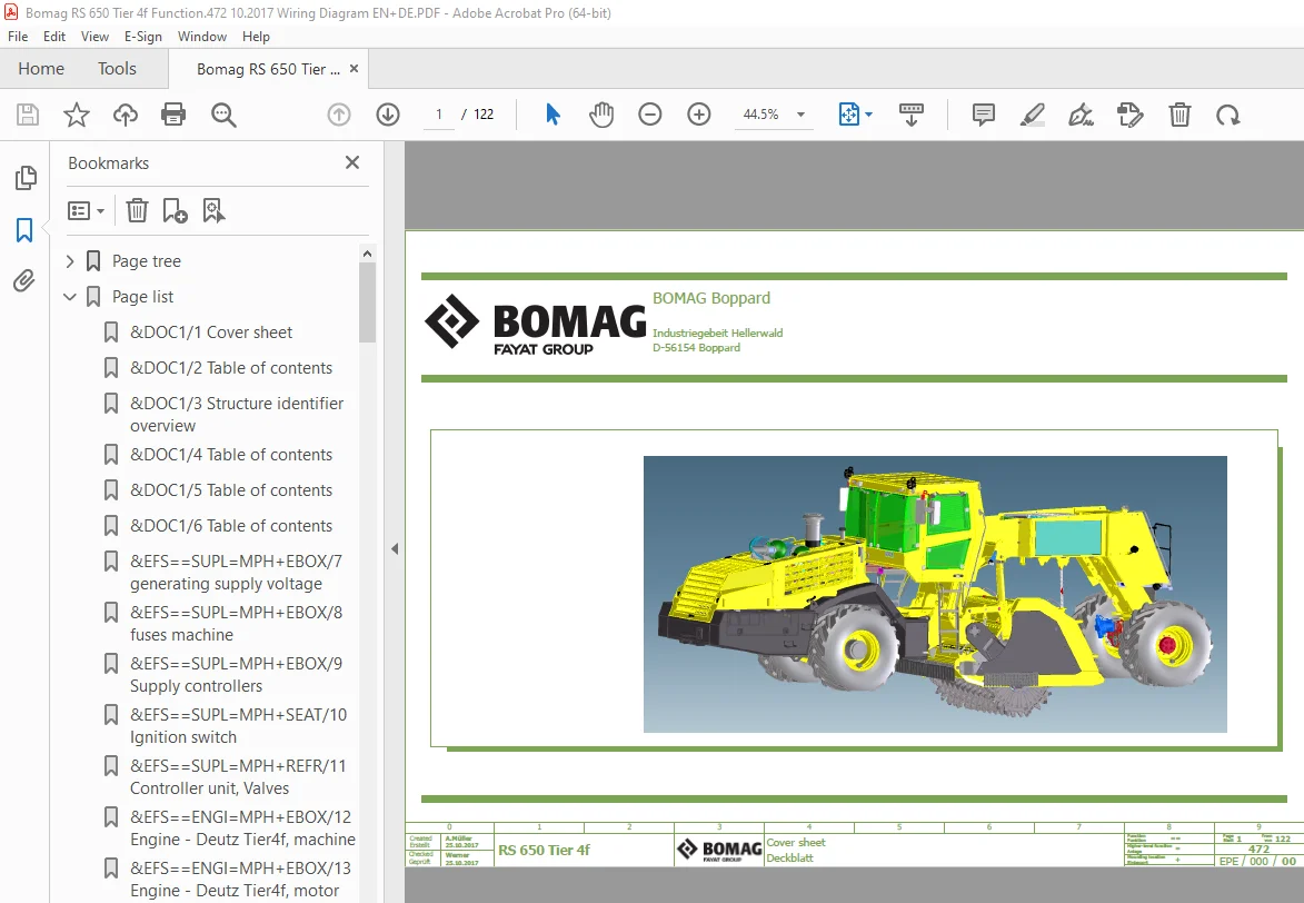
Bomag RS 650 Tier 4f Function.472 Wiring Diagram Manual EN_DE – PDF DOWNLOAD
$26.95
Bomag RS 650 Tier 4f Function.472 Wiring Diagram Manual EN_DE – PDF DOWNLOAD
Description
Bomag RS 650 Tier 4f Function.472 Wiring Diagram Manual EN_DE – PDF DOWNLOAD
FILE DETAILS:
Bomag RS 650 Tier 4f Function.472 Wiring Diagram Manual EN_DE – PDF DOWNLOAD
Language : English_German
Pages : 122
Downloadable : Yes
File Type : PDF
IMAGES PREVIEW OF THE MANUAL:
TABLE OF CONTENTS:
Bomag RS 650 Tier 4f Function.472 Wiring Diagram Manual EN_DE – PDF DOWNLOAD
Page tree 1
&DOC1 Leading documentation 1
1 Cover sheet 1
2 Table of contents 2
3 Structure identifier overview 3
4 Table of contents 4
5 Table of contents 5
6 Table of contents 6
&EFS Circuit diagram 7
=MPH Basic machine 7
7 generating supply voltage 7
8 fuses machine 8
9 Supply controllers 9
10 Ignition switch 10
11 Controller unit, Valves 11
12 Engine – Deutz Tier4f, machine 12
13 Engine – Deutz Tier4f, motor 13
14 Engine – Deutz Tier4f, motor 14
15 Engine – Deutz Tier 4f, SCR system 15
16 Engine – Deutz Tier4f, SCR System 16
17 Engine – Deutz Tier 4f, SCR NOX Waste 17
18 Deutz TCD 4 1/6 1 – Exhaust aftertreatment Kat 1 18
19 Deutz TCD 4 1/6 1 – Exhaust aftertreatment Kat 2 19
20 Engine and hydraulic oil cooler 20
21 communication CAN1 / CAN2 21
22 communication CAN3 / serial 22
23 security devices and engine speed adjustment 23
24 actuation drive functions 24
25 sensors and valves drive 25
26 Buckling-link steering 26
27 rear axle steering 27
28 Adjustment front, rear and mixing gates 28
29 sensors and valves Milling 29
30 Milling-Tool exchange 30
31 Sensors and valves / Rotor Hood 31
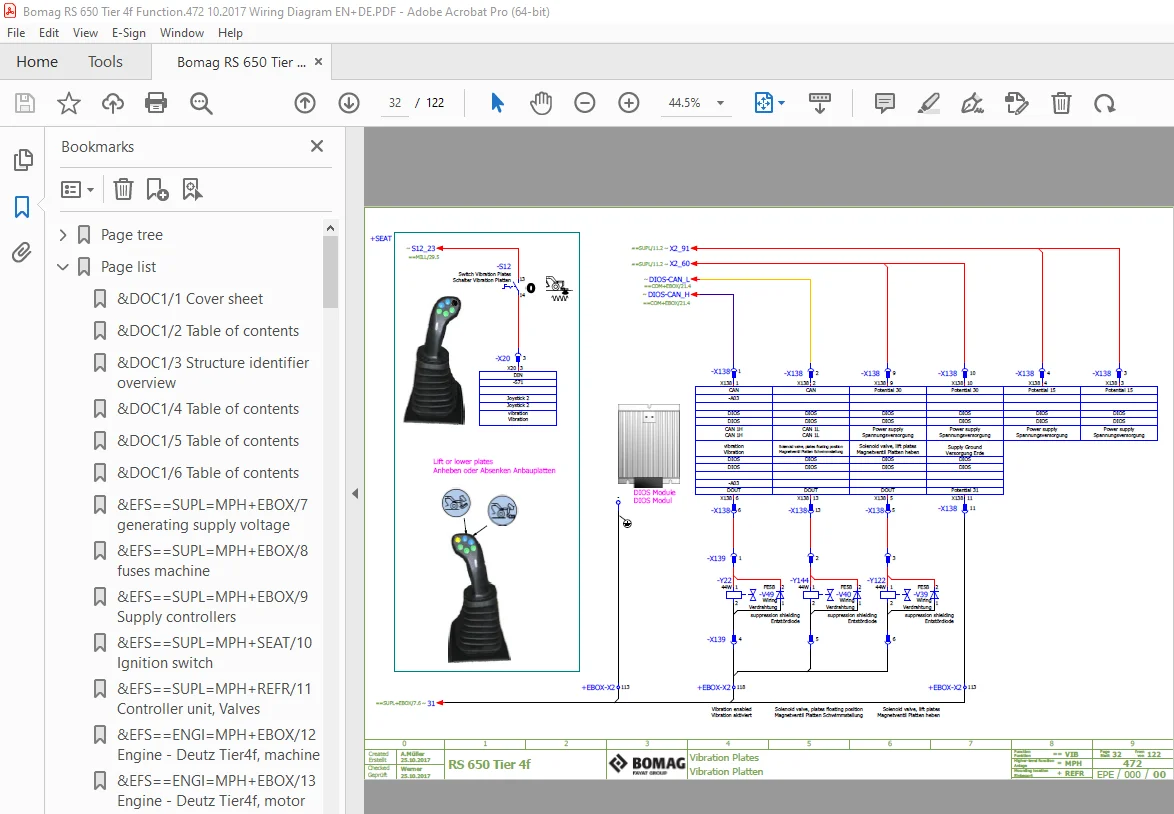
32 Vibration Plates 32
33 Bomag telematics 33
34 signals gear-box monitoring and fuel level sensor 34
35 signals data collector engine and hydraulic 35
36 adjustment cabin 36
37 fuses cabin 37
38 Windscreen Wipers and Washers 38
39 mounting parts cabin 39
40 Air conditioner and Heating 40
41 Rear View Camera, Printer and Mirror adjustment 41
42 Working lights 42
=WDP Water dosage plant (option) 43
43 dosing milling water 43
44 spray valves water 44
=BDP Bitumen dosage plant (option) 45
45 voltage supply BOMAG 45
46 output signals dosage controller 46
47 input signals dosage controller 47
48 flowmeter bitumen & emulsion 48
49 spray valves bitumen 49
50 adaption valve modules BLM 2 and BLM 3 50
51 sensors and additional valves for spray module 51
52 combi-valves 1 10 52
53 combi-valves 11 21 53
54 components pump module 54
55 heating and reaction water system 55
&DOC2 Reports and drawings 56
50 Component-Listing 56
51 Component-Listing 57
52 Component-Listing 58
53 Component-Listing 59
54 Component-Listing 60
55 Component-Listing 61
56 Component-Listing 62
57 Component-Listing 63
58 Component-Listing 64
59 Component-Listing 65
60 Component-Listing 66
61 Component-Listing 67
62 Component-Listing 68
63 Component-Listing 69
64 Component-Listing 70
65 Component-Listing 71
66 Component-Listing 72
79 Illustrations terminal strips 73
80 Illustrations terminal strips 74
81 Illustrations terminal strips 75
82 Illustrations terminal strips 76
83 Illustrations terminal strips 77
84 Overview E-Box 78
85 Assembly Plate overview 79
86 system overview / modules bitumen plant 80
87 Overview EAT system in RS 650 Tier 4f 81
100 Terminal diagram 82
101 Terminal diagram 83
102 Terminal diagram 84
103 Terminal diagram 85
104 Terminal diagram 86
105 Terminal diagram 87
120 Pin overview A66 88
121 Pin overview A66 89
122 Pin overview A80 90
123 Pin overview A81 91
124 Pin overview A145 92
125 Pin overview A03 93
126 Pin overview A83 94
127 Pin overview A83 95
128 Pin overview A98 96
129 Pin overview A104 97
140 Plug diagram 98
141 Plug diagram 99
142 Plug diagram 100
143 Plug diagram 101
144 Plug diagram 102
145 Plug diagram 103
146 Plug diagram 104
147 Plug diagram 105
148 Plug diagram 106
149 Plug diagram 107
150 Plug diagram 108
151 Plug diagram 109
152 Plug diagram 110
153 Plug diagram 111
154 Plug diagram 112
155 Plug diagram 113
156 Plug diagram 114
157 Plug diagram 115
158 Plug diagram 116
159 Plug diagram 117
160 Plug diagram 118
161 Plug diagram 119
162 Plug diagram 120
163 Plug diagram 121
164 Plug diagram 122
Page list 1
&DOC1/1 Cover sheet 1
&DOC1/2 Table of contents 2
&DOC1/3 Structure identifier overview 3
&DOC1/4 Table of contents 4
&DOC1/5 Table of contents 5
&DOC1/6 Table of contents 6
&EFS==SUPL=MPH+EBOX/7 generating supply voltage 7
&EFS==SUPL=MPH+EBOX/8 fuses machine 8
&EFS==SUPL=MPH+EBOX/9 Supply controllers 9
&EFS==SUPL=MPH+SEAT/10 Ignition switch 10
&EFS==SUPL=MPH+REFR/11 Controller unit, Valves 11
&EFS==ENGI=MPH+EBOX/12 Engine – Deutz Tier4f, machine 12
&EFS==ENGI=MPH+EBOX/13 Engine – Deutz Tier4f, motor 13
&EFS==ENGI=MPH+EBOX/14 Engine – Deutz Tier4f, motor 14
&EFS==ENGI=MPH+EBOX/15 Engine – Deutz Tier 4f, SCR system 15
&EFS==ENGI=MPH+EBOX/16 Engine – Deutz Tier4f, SCR System 16
&EFS==ENGI=MPH+MOT/17 Engine – Deutz Tier 4f, SCR NOX Waste 17
&EFS==ENGI=MPH+MOT/18 Deutz TCD 4 1/6 1 – Exhaust aftertreatment Kat 1 18
&EFS==ENGI=MPH+MOT/19 Deutz TCD 4 1/6 1 – Exhaust aftertreatment Kat 2 19
&EFS==ENGI=MPH+REFR/20 Engine and hydraulic oil cooler 20
&EFS==COM=MPH+EBOX/21 communication CAN1 / CAN2 21
&EFS==COM=MPH+EBOX/22 communication CAN3 / serial 22
&EFS==DRIV=MPH+SEAT/23 security devices and engine speed adjustment 23
&EFS==DRIV=MPH+SEAT/24 actuation drive functions 24
&EFS==DRIV=MPH+FRFR/25 sensors and valves drive 25
&EFS==STER=MPH+EBOX/26 Buckling-link steering 26
&EFS==STER=MPH+REFR/27 rear axle steering 27
&EFS==MILL=MPH+SEAT/28 Adjustment front, rear and mixing gates 28
&EFS==MILL=MPH+REFR/29 sensors and valves Milling 29
&EFS==MILL=MPH+REFR/30 Milling-Tool exchange 30
&EFS==MILL=MPH+REFR/31 Sensors and valves / Rotor Hood 31
&EFS==VIB=MPH+REFR/32 Vibration Plates 32
&EFS==DATA=MPH+EBOX/33 Bomag telematics 33
&EFS==DATA=MPH+EBOX/34 signals gear-box monitoring and fuel level sensor 34
&EFS==DATA=MPH+FRFR/35 signals data collector engine and hydraulic 35
&EFS==COMF=MPH+REFR/36 adjustment cabin 36
&EFS==COMF=MPH+CAB/37 fuses cabin 37
&EFS==COMF=MPH+CAB/38 Windscreen Wipers and Washers 38
&EFS==COMF=MPH+CAB/39 mounting parts cabin 39
&EFS==COMF=MPH+CAB/40 Air conditioner and Heating 40
&EFS==COMF=MPH+CAB/41 Rear View Camera, Printer and Mirror adjustment 41
&EFS==ILUM=MPH+SEAT/42 Working lights 42
&EFS==WDOS=WDP+EBOX/43 dosing milling water 43
&EFS==WSPR=WDP+HOD/44 spray valves water 44
&EFS==BDOS=BDP+EBOX/45 voltage supply BOMAG 45
&EFS==BDOS=BDP+EBOX/46 output signals dosage controller 46
&EFS==BDOS=BDP+EBOX/47 input signals dosage controller 47
&EFS==BDOS=BDP+PUM/48 flowmeter bitumen & emulsion 48
&EFS==BSPR=BDP+REFR/49 spray valves bitumen 49
&EFS==BSPR=BDP+REFR/50 adaption valve modules BLM 2 and BLM 3 50
&EFS==BSPR=BDP+REFR/51 sensors and additional valves for spray module 51
&EFS==BSPR=BDP+REFR/52 combi-valves 1 10 52
&EFS==BSPR=BDP+REFR/53 combi-valves 11 21 53
&EFS==BSPR=BDP+PUM/54 components pump module 54
&EFS==BSPR=BDP+RWT/55 heating and reaction water system 55
&DOC2/50 Component-Listing 56
&DOC2/51 Component-Listing 57
&DOC2/52 Component-Listing 58
&DOC2/53 Component-Listing 59
&DOC2/54 Component-Listing 60
&DOC2/55 Component-Listing 61
&DOC2/56 Component-Listing 62
&DOC2/57 Component-Listing 63
&DOC2/58 Component-Listing 64
&DOC2/59 Component-Listing 65
&DOC2/60 Component-Listing 66
&DOC2/61 Component-Listing 67
&DOC2/62 Component-Listing 68
&DOC2/63 Component-Listing 69
&DOC2/64 Component-Listing 70
&DOC2/65 Component-Listing 71
&DOC2/66 Component-Listing 72
&DOC2/79 Illustrations terminal strips 73
&DOC2/80 Illustrations terminal strips 74
&DOC2/81 Illustrations terminal strips 75
&DOC2/82 Illustrations terminal strips 76
&DOC2/83 Illustrations terminal strips 77
&DOC2/84 Overview E-Box 78
&DOC2/85 Assembly Plate overview 79
&DOC2/86 system overview / modules bitumen plant 80
&DOC2/87 Overview EAT system in RS 650 Tier 4f 81
&DOC2/100 Terminal diagram 82
&DOC2/101 Terminal diagram 83
&DOC2/102 Terminal diagram 84
&DOC2/103 Terminal diagram 85
&DOC2/104 Terminal diagram 86
&DOC2/105 Terminal diagram 87
&DOC2/120 Pin overview A66 88
&DOC2/121 Pin overview A66 89
&DOC2/122 Pin overview A80 90
&DOC2/123 Pin overview A81 91
&DOC2/124 Pin overview A145 92
&DOC2/125 Pin overview A03 93
&DOC2/126 Pin overview A83 94
&DOC2/127 Pin overview A83 95
&DOC2/128 Pin overview A98 96
&DOC2/129 Pin overview A104 97
&DOC2/140 Plug diagram 98
&DOC2/141 Plug diagram 99
&DOC2/142 Plug diagram 100
&DOC2/143 Plug diagram 101
&DOC2/144 Plug diagram 102
&DOC2/145 Plug diagram 103
&DOC2/146 Plug diagram 104
&DOC2/147 Plug diagram 105
&DOC2/148 Plug diagram 106
&DOC2/149 Plug diagram 107
&DOC2/150 Plug diagram 108
&DOC2/151 Plug diagram 109
&DOC2/152 Plug diagram 110
&DOC2/153 Plug diagram 111
&DOC2/154 Plug diagram 112
&DOC2/155 Plug diagram 113
&DOC2/156 Plug diagram 114
&DOC2/157 Plug diagram 115
&DOC2/158 Plug diagram 116
&DOC2/159 Plug diagram 117
&DOC2/160 Plug diagram 118
&DOC2/161 Plug diagram 119
&DOC2/162 Plug diagram 120
&DOC2/163 Plug diagram 121
&DOC2/164 Plug diagram 122
S.V 08/24