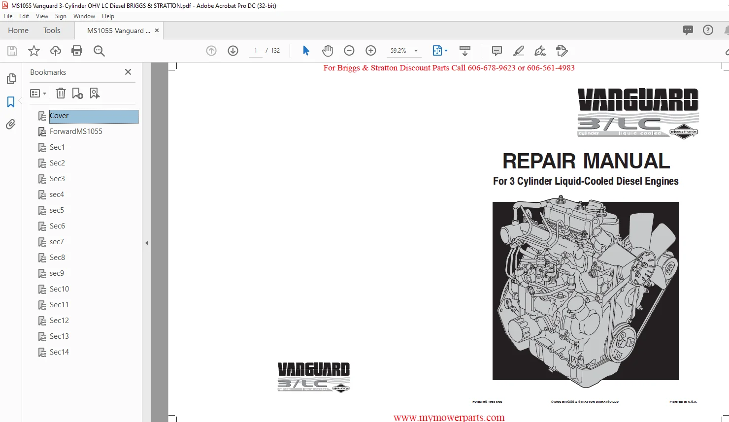
Briggs & Stratton 3 Cylinder Liquid-Cooled Diesel Engine Repair Manual – PDF DOWNLOAD
Original price was: $86.95.$26.95Current price is: $26.95.
Briggs & Stratton 3 Cylinder Liquid-Cooled Diesel Engine Repair Manual – PDF DOWNLOAD
Description
Briggs & Stratton 3 Cylinder Liquid-Cooled Diesel Engine Repair Manual – PDF DOWNLOAD
FILE DETAILS:
Briggs & Stratton 3 Cylinder Liquid-Cooled Diesel Engine Repair Manual – PDF DOWNLOAD
Language : English
Pages : 132
Downloadable : Yes
File Type : PDF
Size: 4.33 MB
IMAGES PREVIEW OF THE MANUAL:
DESCRIPTION:
Briggs & Stratton 3 Cylinder Liquid-Cooled Diesel Engine Repair Manual – PDF DOWNLOAD
FOREWORD:
The information, procedures and specifications provided in this repair manual are current as of the date of
publication and subject to change without notice. Appropriate changes will be included in the next revision of this
manual.
GENERAL REPAIR INSTRUCTIONS:
Before attempting a B&SD engine overhaul or a tune-up, it is necessary that your shop be equipped with proper tools,
equipment and mechanics who are thoroughly familiar with Briggs & Stratton engine design and construction. With
your shop thus equipped, this book will serve as a guide in performing the various steps necessary to do a complete
and satisfactory job. Use only genuine replacement parts. Always use recommended service tools.
This engine is designed and manufactured using metric dimensions. The English equivalents provided may have been
rounded up or down to the closest numerical interpretation of the metric dimension.
The terms Inspect, Check, Test and Replace are used as follows:
INSPECT Visual inspection look for signs of wear, scoring, cracks, stripped threads, etc.
CHECK Measure by means of plug gauges, micrometer, feeler gauges, scale, etc.
TEST Analyze with proper test equipment.
REPLACE This usually means to take off the old part and reassemble it or replace it with a new one.
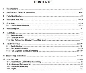
TABLE OF CONTENTS:
Briggs & Stratton 3 Cylinder Liquid-Cooled Diesel Engine Repair Manual – PDF DOWNLOAD
Section 1
GENERAL INFORMATION
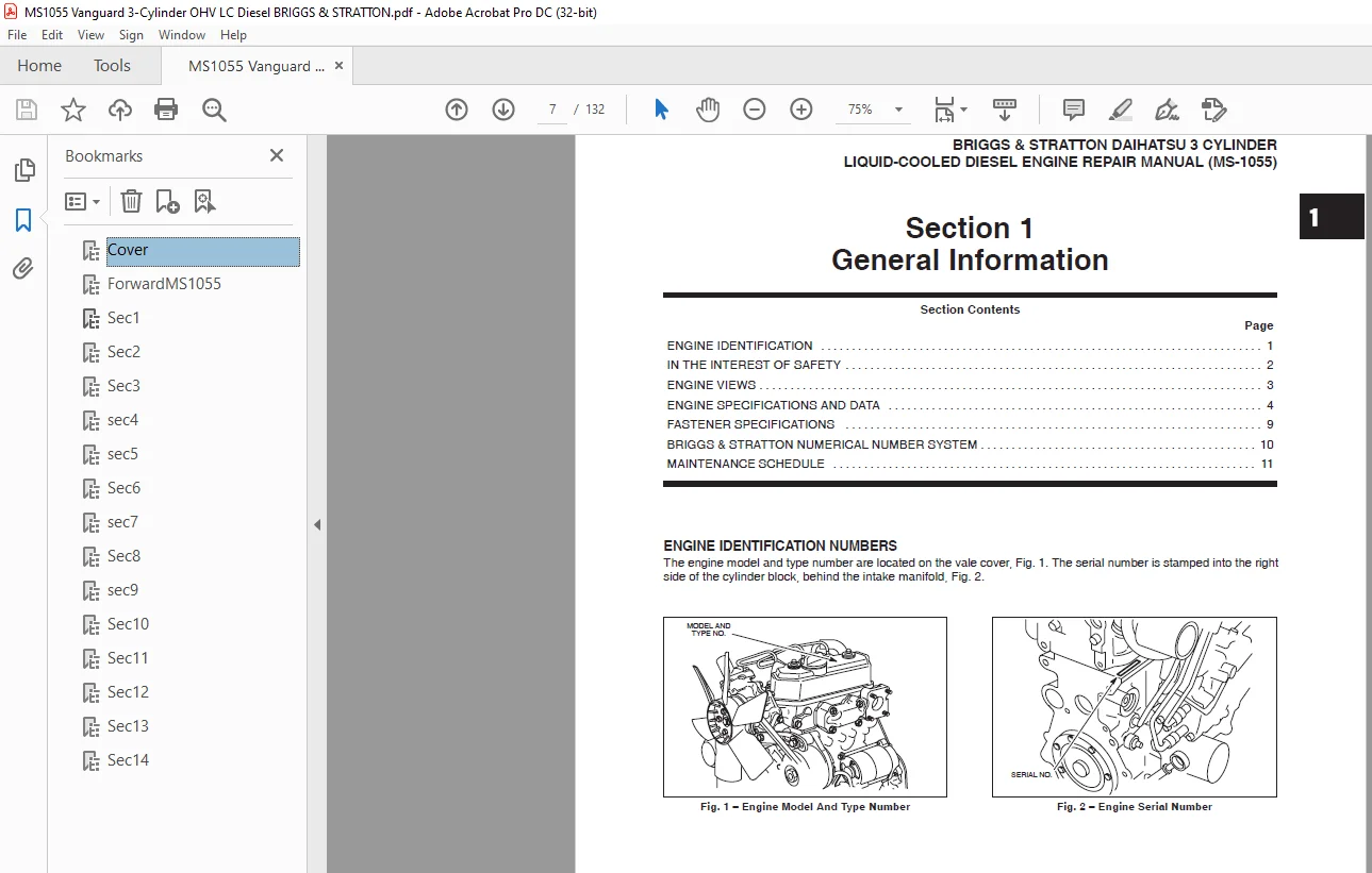
Engine Identification
In The Interest Of Safety
Engine Views
Engine Specifications And Data
Fastener Specifications
Briggs & Stratton Numerical Number System
Maintenance Schedule
2 Section 2
CYLINDER HEAD AND VALVES
Remove Cylinder Head
Disassemble Cylinder Head
Inspect And Repair
Cylinder Head
Valve Guides
Valves
Disassemble Rocker Arm Shaft
Assemble Rocker Arm Shaft
Assemble Cylinder Head
Install Cylinder Head
Adjust Valves
3 Section 3
TIMING GEARS AND GEAR CASE
Remove Timing Gear Cover And Gears
Checking Gears
Remove Gear Case
Replace Timing Gear Cover Oil Seal
Assemble Timing Gear Case And Gears
4 Section 4
FLYWHEEL AND REAR SEAL RETAINER
Removing Flywheel And Rear Seal Retainer
Replacing Oil Seal
Installing Rear Seal Retainer And Flywheel
Install Oil Pan
5 Section 5
CYLINDER BLOCK DISASSEMBLY
Engine Stand Fixture
Cylinder Block Disassembly
6 Section 6
CYLINDER BLOCK INSPECTION AND
REPAIR
Checking Cylinder Block
Replacing Camshaft Bearing
Replacing Camshaft Plug
7 Section 7
CRANKSHAFT, CAMSHAFT AND BEARINGS
Checking Crankshaft
Checking Main Bearing Clearances
Checking Connecting Rod Bearing Clearances
Checking Crankshaft End Play
Checking Camshaft
8 Section 8
PISTON, RINGS AND CONNECTING ROD
INSPECTION AND ASSEMBLY
Disassemble Piston And Connecting Rod
Checking Piston And Rings
Checking Piston Pin And Connecting Rod
Assemble Piston And Connecting Rod
Assemble Piston Rings To Piston
9 Section 9
CYLINDER BLOCK ASSEMBLY
Install Crankshaft
Install Pistons And Connecting Rods
General Assembly
Oil Pickup Tube
Rear Seal Retainer And Starter Motor
Flywheel
Install Timing Gear Case, Camshaft And
Gears
Install Oil Pan
Install Alternator
10 Section 10
FUEL SYSTEM AND RELATED
COMPONENTS
General Information
Injector Pump Timing Specifications
Checking Injector Pump Timing
SECTION CONTENTS (contd)
III
Adjusting Injector Pump Timing
Injectors
Remove Injectors
Checking Injectors
Install Injectors
Fuel Filter General
Draining Water Collector
Change Fuel Filter
Fuel Shut-Off Solenoid
Checking Fuel Shut-Off Solenoid
Wiring
Injector Pump Identification
Engine Speed Identification Chart
Adjust Idle Speed
Adjust Top No Load Speed
11 Section 11
ELECTRICAL SYSTEMS
Electrical System Components
Glow Plug System
Glow Plug Specifications
Remove Glow Plugs
Test Equipment
Testing Glow Plug
Preheat Timer And Glow Relay
Testing Preheat Timer
Testing Glow Relay
Keyswitches
Charging Systems
14 Amp Charging System
Test Equipment
Testing Alternator AC Output
Testing Regulator-Rectifier DC
Output
Testing Charge Indicator Bulb And
Wiring
40 Amp Charging System
Test Equipment
Testing Alternator DC Output
Disassemble Alternator
Checking Bearings
Install Ball Bearing
Check Brushes
Check Regulator
Check Rectifier
Assemble Alternator
Starter System
Starter Current Draw Test Installed
Test Equipment
Testing Starter
Starter Current Draw Test No Load
Testing Starter (No Load)
Starter Solenoid
Equipment To Test Solenoid
Testing Solenoid
Remove Solenoid
Check Pinion And Clutch Assembly
Assemble Pinion And Clutch Assembly
Install Solenoid
Install Solenoid Contacts And Plunger
Disassemble Starter Motor
Inspect Armature Commutator
Inspect Brushes
Replace Brushes
Assemble Starter Motor
Wiring Diagrams
40 Amp Wiring Diagram
14 Amp Wiring Diagrams
12 Section 12
LUBRICATION SYSTEM
Description
Change Oil
Change Oil Filter
Check Oil Pressure
Disassemble Gear Case
Remove Oil Pump
Assemble Gear Case
Install Oil Pump
13 Section 13
COOLING SYSTEM
General Information
Checking Cooling System
Pressure Testing Cooling System
Testing Radiator Cap
Changing Coolant
Thermostat
Removing Thermostat
Checking Thermostat
Installing Thermostat
Water Pump
Inspecting Water Pump
Removing Water Pump
Installing Water Pump
SECTION CONTENTS
14 Section 14
TURBOCHARGER
General Information
Turbocharger Lubrication System
Turbocharger Cooling System
Turbocharger Waste Gate
Turbocharger Pressure Control System
Crankcase Bloeby Recirculating System
Checking Waste Gate Actuator
Servicing And Operating Information
Remove Turbocharger
Checking Turbocharger
Install Turbocharger
Installation Of Coolant Inlet Tube
Questions? Email us: [email protected]
PLEASE NOTE:
- This is the SAME MANUAL used by the dealerships to diagnose your vehicle
- No waiting for couriers / posts as this is a PDF manual and you can download it within 2 minutes time once you make the payment.
- Your payment is all safe and the delivery of the manual is INSTANT – You will be taken to the DOWNLOAD PAGE.
- So have no hesitations whatsoever and write to us about any queries you may have : heydownloadss @gmail.com
S.V