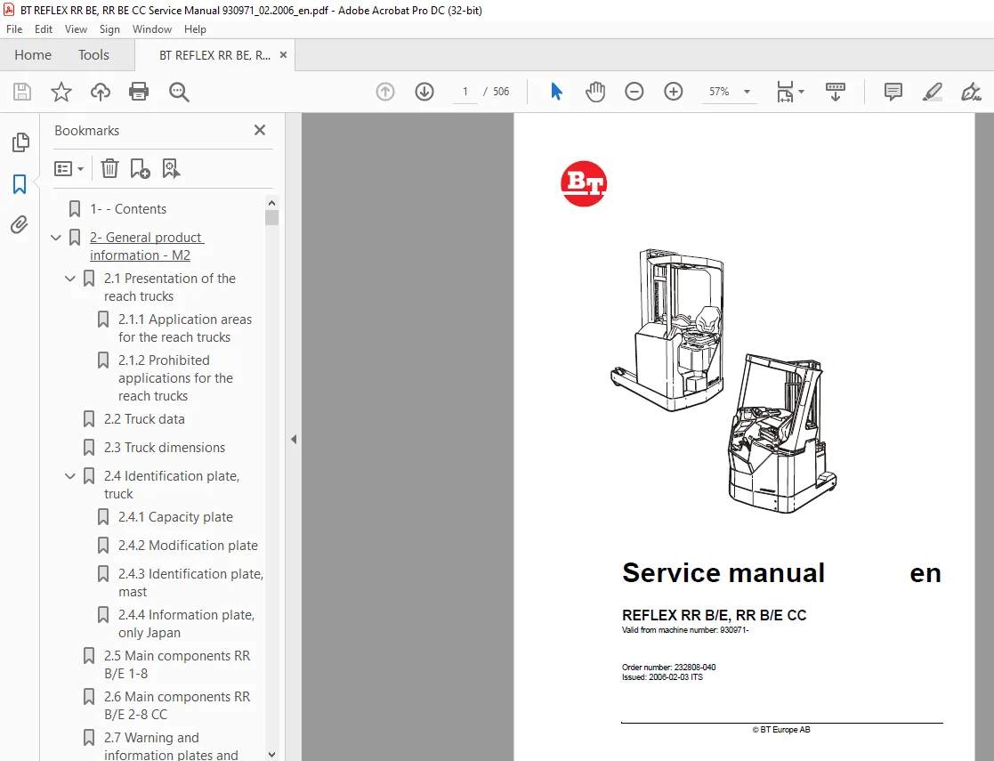
BT Electric Forklift REFLEX RR B/E RR B/E CC Service Manual 232808-040
$30.95
BT Electric Forklift REFLEX RR B/E RR B/E CC Service Manual 232808-040 – PDF DOWNLOAD
Description
BT Electric Forklift REFLEX RR B/E RR B/E CC Service Manual 232808-040 – PDF DOWNLOAD
FILE DETAILS:
BT Electric Forklift REFLEX RR B/E RR B/E CC Service Manual 232808-040 – PDF DOWNLOAD
Language : English
Pages :506
Downloadable : Yes
File Type : PDF
TABLE OF CONTENTS:
BT Electric Forklift REFLEX RR B/E RR B/E CC Service Manual 232808-040 – PDF DOWNLOAD
1- – Contents 3
2- General product information – M2 17
21 Presentation of the reach trucks 17
211 Application areas for the reach trucks 17
212 Prohibited applications for the reach trucks 17
22 Truck data 18
23 Truck dimensions 19
24 Identification plate, truck 21
241 Capacity plate 21
242 Modification plate 22
243 Identification plate, mast 22
244 Information plate, only Japan 22
25 Main components RR B/E 1-8 23
26 Main components RR B/E 2-8 CC 25
27 Warning and information plates and symbols RR B/E 1-8 27
28 Warning and information plates and symbols RR B/E 2-8 CC 29
3- Technical data – M4 31
31 General tightening torque 35
311 Galvanised, non-oiled bolts 35
312 Untreated, oiled bolts 35
4- Introduction, maintenance – P1 37
41 Safety regulations during maintenance work 37
42 Cleaning and washing 38
421 Cleaning the exterior 38
422 Cleaning the motor compartment 39
423 Electrical components 39
43 Safe lifting 39
44 Opening motor compartment 40
441 RR B 1-8 40
45 Cab tilting 41
451 RR E 1-8 41
452 RR E 2-8 CC 43
5- Preventive maintenance – P2 45
51 Maintenance Schedule 45
511 RR B/E 1-8 45
512 RR B/E 2-8 CC 55
6- Oil and grease specification – P3 65
7- Tools – P4 67
71 Super Seal connector 67
711 AMP connector 68
712 AMP microtimer 69
713 Diverse tools 70
8- Cab heating/ventilation – 0630 77
81 General 77
82 Air conditioning unit 77
821 Ventilation 77
822 Main heater 77
823 Auxiliary heater 77
824 Temperature 77
825 Air direction 78
826 Fuses 78
827 Air filter 78
828 Emergency exit (12) 79
829 Lighting 79
9- Driver protection – 0840 81
91 General 81
92 Tilt Stops 82
921 Inspection and Adjustment 82
922 Removing the tilt stops 83
10- Electric pump motor -1710 85
101 General 85
102 Dismantling the pump motor 85
103 Dismantling and assembling the pump motor 86
1031 Dismantling 86
1032 Assembling 86
104 Bearing replacement 87
1041 Dismantling 87
1042 Assembling 88
105 Installation instructions for external temperature sensor 89
11- Electric steering motor – 1730 93
111 General 93
112 Replacing the steering motor 93
1121 Dismantling 93
1122 Assembling 93
113 Dismantling and assembling the carbon brushes 94
12- Electric drive motor – 1760 95
121 General 95
122 Dismantling the drive motor 95
123 Dismantling and assembling the drive motor 96
1231 Dismantling the drive motor 96
Removing the gear wheel 96
Removing the brakes 96
1232 Assembling the drive motor 97
Assembling the brakes 97
Assembling the gear wheel 97
124 Bearing replacement 98
1241 Dismantling 98
1242 N-side 98
D-side 98
1243 Assembling 99
N-side 99
D-side 99
125 Installation instructions for external temperature sensor100
13- Mechanical drive gear unit – 2550103
131 General103
132 Components/data for the drive assembly/transmission103
1321 Component placement104
1322 Technical data106
1323 Dismantling the transmission106
133 Replacing the drive motor/drive transmission107
1331 Dismantling the drive motor107
1332 Dismantling the gear wheel107
1333 Dismantling the drive transmission107
1334 Assembling the transmission108
1335 Installing the drive motor109
1336 Assembling the gear wheel109
134 Checking/replacing the oil110
1341 Checking/refilling the oil110
1342 Changing the Oil110
135 Repairs111
1351 Replacing the drive shaft sealing ring111
Dismantling111
Assembling112
1352 Leakage from the upper cover113
1353 Leakage from the lower cover113
1354 Replacing wheel bolts114
14- Travel brake system – 31001115
Without support arm brakes115
141 General115
142 Operating description115
1421 Releasing the accelerator116
1422 Travel direction selector116
1423 Pressing down the brake pedal117
1424 Parking brake118
1425 Emergency brake118
143 Electromechanical disc brake, drive motor119
1431 Assembling119
1432 Dismantling120
1433 Inspection120
1434 Assembling120
144 Maintenance121
1441 Adjusting the play121
1442 Wear121
1443 Check the braking force122
15- Travel brake system – 31002123
With support arm brake123
151 General123
152 Operating description123
1521 Releasing the accelerator124
1522 Travel direction selector124
1523 Pressing down the brake pedal124
1524 Parking brake124
1525 Emergency braking125
153 Electromechanical disc brake, drive motor126
1531 Assembling126
1532 Dismantling127
1533 Inspection127
1534 Assembling127
154 Maintenance128
1541 Adjusting the play128
1542 Wear128
1543 Check the braking force129
155 Multiple disc brake, support arm130
1551 Assembling130
1552 Dismantling131
1553 Inspection132
1554 Assembling132
156 Maintenance132
1561 Adjusting the play133
16- Drive wheel – 3530135
161 General135
162 Dismantling the drive wheel135
163 Assembling the drive wheel135
17- Fork/support arm wheel – 35501137
171 General137
172 Dismantling the wheel138
173 Assembling the wheel139
174 Dismantling/assembling the wheel bearings141
1741 265 mm wheel and 300 mm wheel without brakes141
Dismantling the bearing141
Assembling bearings141
1742 300 mm wheel with brake and 350 mm wheel142
Dismantling the bearing142
Assembling bearings142
18- Fork/support arm wheel – 35502143
Valid for T-code 403-404143
181 General143
182 Dismantling the wheel143
183 Assembling the drive wheel144
184 Dismantling the wheel bearings144
185 Assembling the wheel bearings144
19- Mechanical steering system – 4100145
191 General145
192 Replacing the steering generator145
1921 Dismantling145
1922 Assembling145
20- Steering angle sensor – 4350147
201 General147
202 Procedure147
2011 Adjustment of the steering angle sensor148
22- Battery – 5110149
221 Battery dimensions149
222 Setting the battery parameters on RR trucks fitted with Hawker Evolution gel batteries150
2221 General150
2222 Battery recommendation150
2223 Battery installation150
2224 Recommended parameter setting for ventilation regulated batteries151
2225 Instructions for verifying the parameter setting151
21- Electrical system – 5000153
211 Electrical Panel153
212 List of symbols and wiring diagrams154
2121 List of symbols154
2122 Wiring diagram (1/16)157
213 Component list173
2131 Figure 1179
2132 Figure 2179
2133 Figure 3180
2134 Figure 4180
2135 Figure 5181
2136 Figure 6182
2137 Figure 7182
2138 Figure 8183
2139 Figure 9184
21310 Figure 10185
21311 Figure 11186
21312 Figure 12186
214 Functional description187
2141 Truck not started up187
2142 Truck started up188
2143 Selection of travel direction189
On the operating console189
On the left-hand handle189
On the accelerator189
2144 Driving190
2145 Steering191
2146 Steering wheel indicator191
2147 Braking192
Auto-brakes192
Motor brakes (electric)192
Foot brake192
Parking brake192
2148 Fork lift193
2149 Maximum height193
21410 Maximum height194
21411 Fork lowering194
21412 Mast out/in195
21413 Fork tilt up/down195
21414 Hydraulic function 4195
21415 Hydraulic function 5196
21416 Cab tilt196
21417 Height indication197
21418 Height pre-set197
21419 Weighing197
21420 Driver identification198
Without pin code198
With pin code198
23- Transistor panel – 5460199
231 Frequency converter199
2311 General description199
2312 Terminal connections and pole bolts200
2313 Technical data201
2314 Programming201
24- Electronic card – 5710203
241 General description203
242 Terminal connections and voltages on A5204
2421 10X204
2422 20X205
2423 30X205
2424 40X206
2425 50X206
2426 60X207
2427 70X207
2428 80X208
2429 90X208
243 Adjusting the lowering speed209
244 Display and programming210
2441 Keyboard210
Clock211
Driver parameters 1-7211
245 Parameter settings for all parameters212
Clock213
Parameters213
2451 Parameter 1217
2452 Parameter 2217
2453 Parameter 3217
2454 Parameter 4217
2455 Parameter 5217
2456 Parameters 6 and 7217
2457 Parameter 11217
2458 Parameter 12217
2459 Parameters 13 to 14217
24510 Parameters 15 and 16218
24511 Parameters 17 and 18218
24512 Parameter 19218
24513 Parameter 20219
24514 Parameter 21219
24515 Parameter 22220
24516 Parameter 23220
24517 Parameter 24220
24518 Parameter 25220
24519 Parameter 26220
24520 Parameter 27220
24521 Parameter 28220
24522 Parameter 29220
24523 Parameter 30221
24524 Parameter 37221
24525 Parameter 38221
24526 Parameter 39222
24527 Parameters 40 to 42222
24528 Other parameters222
246 Operating Time223
2461 Installing a new card in the truck223
247 Warning Codes224
248 Error codes225
2481 Error mode225
2482 Safety logic226
249 Warning codes without registration227
2410 Warning codes with registration248
2411 Error codes267
24111 Error codes with registration268
25- Keyboard297
251 General297
252 Display297
2521 Description of the keyboard symbols298
253 Function299
2531 Function 0299
2532 Function 1299
2533 Function 2299
2534 Function 3300
254 Programming300
2541 LED status300
2542 Driver codes301
26- Hydraulics – 6000303
261 General303
262 Symbols303
2621 Hydraulics diagram 1 (4)305
2622 Hydraulics diagram 2 (4)306
2623 Hydraulics diagram 3 (4)307
2624 Hydraulics diagram 4 (4)308
263 List of symbols309
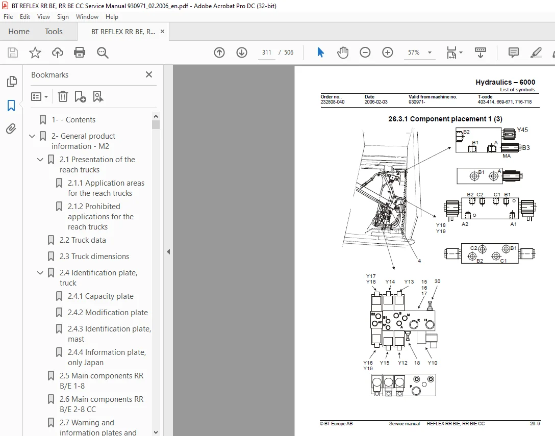
2631 Component placement 1 (3)311
2632 Component placement 2 (3)312
2633 Component placement 3 (3)313
264 Adjusting fork lowering314
265 Adjusting the maximum lifting capacity315
27- Hydraulic pump – 6140317
271 General317
272 Replacing the hydraulic pump317
2721 Dismantling317
2722 Assembling318
28- Hydraulic connections – 6230319
281 General319
282 Tightening torque for hydraulic connections319
2821 Conical connection with O-ring319
2822 Tredo seal320
2823 Pipe coupling320
2824 Connection screwed into aluminium320
2825 Connection screwed into steel321
Pressure class L321
29- Mast mounted hose reel – 6370323
291 General323
292 Assembling323
293 Check after assembly324
30- Main lift cylinder – 6610325
301 General325
302 Tools325
303 Dismantling the lift cylinders from the mast326
304 Dismantling the cylinder326
3041 Dismantling the rod seal, guide ring, guide ring holder and locking ring in lift cylinder327
3042 Fit the locking ring, rod seal, guide ring and guide ring holder in the lift cylinder327
3043 Dismantling and assembling the hose rupture valve328
305 Assembling the cylinder328
3051 Assembling the cylinder in the mast328
31- Free lift cylinder – 6620329
311 General329
312 Tools329
313 Dismantling330
3131 Dismantling the cylinder331
314 Dismantle the rod seal and support ring331
3141 Assembling the rod seal and support ring331
315 Dismantling the piston332
3151 Fitting the piston in the free lift cylinder332
316 Dismantling and assembling the hose rupture valve332
317 Assembling the cylinder333
318 Assembly333
32- Reach cylinder – 6650335
321 General335
322 Assembling and dismantling the reach cylinder335
323 Dismantling335
3231 Dismantling the cylinder336
3232 Dismantle the rod seal and the support ring336
3233 Assembling the rod seal and the support ring336
3234 Dismantling the ram337
3235 Assembling the ram337
3236 Assembling the cylinder337
324 Assembling337
33- Tilt cylinder – 66601339
331 General339
332 Mast with valve on the fork carriage339
3321 Dismantling the fork carriage339
3322 Dismantling the cylinder340
3323 Dismantling the rod seal340
3324 Dismantling the ram341
3325 Assembling the ram341
3326 Assembling the rod seal341
3327 Assembling the cylinder341
3328 Assembling the fork carriage342
333 Mast without valve on the fork carriage343
3331 Dismantling the fork carriage343
3332 Dismantling the cylinder344
3333 Dismantling the rod seal344
3334 Dismantling the ram344
3335 Assembling the ram344
3336 Assembling the rod seal345
3337 Assembling the cylinder345
3338 Assembling the fork carriage345
34- Tilt cylinder – 66602347
341 General347
342 Dismantling the cylinder from the truck347
343 Dismantling and assembling the cylinder348
3431 Dismantling the cylinder348
3432 Dismantle the seals and the support ring348
3433 Assembling the rod seal and the support ring349
3434 Dismantling the ram349
3435 Assembling the ram349
3436 Assembling the cylinder349
344 Refitting the cylinder in the truck350
35- Main mast -7100351
351 General351
352 List of tools351
353 Transporting the truck352
354 Assembling the mast353
355 Dismantling the mast358
356 Adjusting the play359
3561 Adjusting the mast play362
Lateral play362
3562 Radial play363
357 Assembly363
36- Main lift chain system – 7120365
361 General365
362 Checking the chain setting365
363 Chain inspection365
3631 Noise365
3632 Surface rust365
3633 Rusty links365
3634 Stiff links366
3635 Bolt rotation366
3636 Loose bolts366
3637 Outline wear367
3638 Stretching368
3639 Damage369
36310 Damaged discs369
36311 Damaged bolts369
36312 Dirty chain369
364 Cleaning369
365 Lubrication370
37- Lifting devices – 7400371
371 General371
3711 Inspection intervals371
3712 Inspection371
3713 Surface cracks371
3714 Difference in height between the fork tips371
3715 Position locks371
3716 Legible markings371
3717 Fork blade and shaft372
3718 Assembly aid on fork372
3719 Repairs and testing372
Repairs372
Testing the yield point372
Fork373
Fixed extended fork373
372 Extended forks with adjustable fork length374
373 Manual telescopic forks376
3731 Assembly376
3732 Maintenance377
374 Hydraulic telescopic forks378
3741 Assembly instructions378
Telescopic forks with separate flow dividers379
Commissioning of telescopic forks with separate flow dividers380
Telescopic forks with integrated flow dividers381
Commissioning of telescopic forks with integrated flow dividers383
375 Maintenance383
3751 Maintenance383
376 Troubleshooting, telescopic forks with separate flow dividers384
3761 Troubleshooting for telescopic forks with integrated flow dividers386
3762 Instructions for replacing hydraulic parts388
Disassembly388
Assembly388
377 Fork carriage390
3771 Checking the fork carriage’s wearing strip390
3772 Lubrication391
378 Fork spread unit392
3781 Servicing of fork spread unit392
38- Battery charger – 8340393
381 General393
382 Installation394
383 Functional description394
3831 Display functions394
3832 Charging process394
3833 Shutdown conditions395
3834 Delayed power on and charging395
3835 Extra charging395
3836 Equalised charging396
3837 Current and voltage characteristics396
3838 Safety shutdowns396
3839 Display and keyboard397
Reading of analogue measurement values397
Error indication and error messages398
Reading statistics from the previous charge399
Reading of long term statistics400
Storing parameters400
Reading parameters401
Battery specific parameters401
Charger specific parameters402
Mains voltage codes402
Other functions402
Changing parameters403
38310 Acid circulation403
General403
BTM with acid circulation403
Pump type APE, VPM404
Pump type API404
384 Service and maintenance404
3841 Basic programming, code 30404
3842 Resetting the statistics, code 31404
3843 Calibrating the measurement value405
Calibrating the current’s zero value and temperatures, code 21405
Calibrating the battery voltage’s measurement value, code 20405
Calibrating the charging current, code 25406
Calibrating the mains voltage display, code 26406
3844 Calibrating and programming API406
Calibrating zero pressure406
Calibrating the pressure406
Programming the alarm limits406
Programming the API function407
3845 Adjusting the charging characteristics407
3846 Trouble shooting408
Error message, analysis and action408
Errors without indication409
3847 Trouble shooting acid circulation409
3848 Service measures409
Switching to the timer charger410
Replacing the display card410
Replacing the computer board411
Replacing the mother board411
Replacing the diodes411
3849 Preventive maintenance411
39- Control/computer equipment – 8700413
391 General413
392 Connection413
393 Layout414
3931 Main window414
3932 Nodes414
3933 Icons415
3934 Tool buttons and menu list416
3935 Information window416
3936 Status row416
394 Function for connection417
395 Function for disconnecting417
396 Function for program downloading417
3961 Normal loading418
3962 Loading in old versions of the electronic card418
3963 Emergency loading418
397 Function for truck report419
398 Function for parameters420
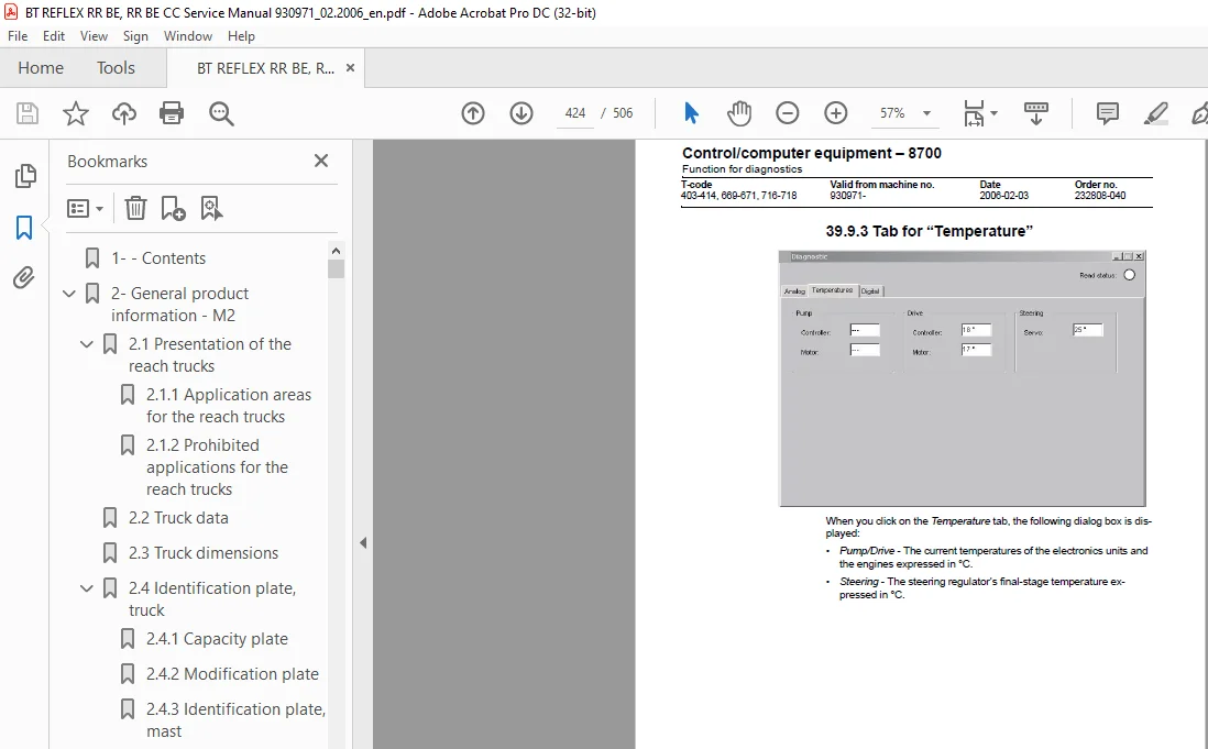
399 Function for diagnostics422
3991 Signal colours422
3992 Tab for “Analogue”423
3993 Tab for “Temperature”424
3994 Tab for “Digital”425
3910 Other menu functions426
39101 Save to file426
39102 Loading from a file426
39103 Resetting the CAN adapter426
39104 Deleting the fault code log426
39105 Resetting the hour meter426
39106 Reading the fault code log426
39107 Adjusting the date/time426
39108 Adjusting the hour meter on older cards427
39109 Help427
About TruckCom427
391010 Conclude427
3911 Specifications427
3912 Installation428
39121 Installation on a PC with Windows XP/ 2000/NT428
39122 IInstallation on a PC with Windows 95/ 98428
39123 In the event of any problems with communication with CAN429
39124 Uninstallation429
40- Extra warning light/alarm – 9370431
401 General431
402 Wiring diagram433
41- Positioning equipment – 9390435
411 General435
412 Height indication436
413 Function437
414 Display438
415 Height pre-set439
416 Function440
417 Display441
4171 Description of the display symbols442
418 Assembly of height pre-set443
419 Programming443
4191 Programming a level443
Collect level443
Leave level444
4192 Deleting programmed levels444
4110 Automatic driving445
41101 Collect load445
41102 Depositing a load446
41103 Inspection446
4111 Parameters447
41111 Parameter 1447
41112 Parameter 2447
41113 Parameter 3448
41114 Parameter 4448
41115 Parameter 5448
41116 Parameter 7449
41117 Parameter 8449
41118 Parameter 9449
4112 Programming parameters450
4113 Error codes452
42- TV equipment – 9390453
421 General453
422 Camera mounted on fork453
4221 Colour camera A51454
4222 Colour monitor A50454
4223 Voltage converter A10456
43- Truck log system, code lock – 9420457
431 General457
432 SD 16457
4321 Login with code (5-digit)457
4322 Logout457
433 Components458
If the truck does not start:460
434 I/O Module460
44- Extra equipment – 9500461
441 Dry powder extinguisher461
In the event of fire, the powder extinguisher should be employed as follows:461
4411 Regular checks of the powder extinguisher – truck driver462
4412 Inspection of powder extinguisher in service inspection of the truck462
45- Instructions for destruction463
451 General463
452 Procedure463
453 Abbreviations464
454 Sorting464
455 Frame/chassis (0300)465
4551 Dismantling465
Material handling465
456 Operator’s seat, cushion (0620)466
4561 Dismantling466
Material handling466
457 Cab heating/ventilation (0630)467
4571 Dismantling467
Material handling467
458 Driver controls (0640)468
4581 Dismantling468
Material handling468
459 Interior fittings RR-B (0680)469
4591 Dismantling469
Material handling470
4510 Interior fittings RR-E (0680)471
45101 Dismantling471
Material handling472
4511 Interior fittings RR-B-CC (0680)473
45111 Dismantling473
Material handling474
4512 Interior fittings RR-E-CC (0680)475
45121 Dismantling475
Material handling476
4513 Rollover guard/head guard (0810)477
45131 Dismantling477
Material handling477
4514 Finger protectors (0820)477
45141 Dismantling477
Material handling477
4515 Finger/foot protectors (0820)478
45151 Dismantling478
Material handling478
4516 Finger/foot protectors (0820)479
45161 Dismantling479
Material handling479
4517 Electric motors (1700)480
45171 Dismantling480
Material handling480
4518 Electric fan motor (1740)481
45181 Dismantling481
Material handling481
4519 Drive unit, final gear (2500)482
45191 Dismantling482
Material handling482
4520 Wheels (3500)483
45201 Dismantling483
Material handling483
4521 Electric steering system (4300)484
45211 Dismantling485
Material handling485
4522 General electric equipment (5100)486
45221 Dismantling486
Material handling486
4523 Manöversystem, körfunktion (5300)487
45231 Dismantling487
Material handling487
4524 Power system, drive function (5400)488
45241 Dismantling488
Material handling488
4525 Control system, operation function (5500)489
45251 Dismantling489
Material handling489
4526 Steering/protective electronics (5700)490
45261 Dismantling490
Material handling490
4527 Hydraulic unit (6100)491
45271 Dismantling492
Material handling492
4528 Hydraulic system, fitted on the chassis (6200)493
45281 Dismantling494
Material handling494
4529 Hydraulic system, fitted on the mast (6300)495
45291 Dismantling495
Material handling495
4530 Hydraulcylindrar (6600)496
45301 Dismantling497
Material handling497
4531 Main mast (7100)498
45311 Dismantling498
Material handling498
4532 Lift fork (7410)499
45321 Dismantling499
Material handling499
4533 Optional electric equipment (9300)499
45331 Dismantling499
Material handling499
4534 Radio/CD player (9330)500
45341 Dismantling500
Material handling500
4535 Extra work light (9360)501
45351 Dismantling501
Material handling501
4536 Optional electric equipment (9400)502
45361 Dismantling502
Material handling502
4537 Optional electric equipment (9400)503
45371 Dismantling503
Material handling503
IMAGES PREVIEW OF THE MANUAL:
S.M 5/24