Trusted Business
Verified & Licensed
Virus Free Files
100% Safe Downloads
Secure Payment
SSL Protected
Instant Delivery
Available Immediately
BT Forklift LWE180, LWE200, LPE200-68 Service Manual – PDF DOWNLOAD
$26.95
BT Forklift LWE180, LWE200, LPE200-68 Service Manual – PDF DOWNLOAD
Instant PDF Download
Available immediately
Save to Your Device
Download & keep forever
Antivirus Scanned
100% virus-free
Trusted Worldwide
175,000+ customers
Description
BT Forklift LWE180, LWE200, LPE200-68 Service Manual – PDF DOWNLOAD
FILE DETAILS:
BT Forklift LWE180, LWE200, LPE200-68 Service Manual – PDF DOWNLOAD
Language : English
Pages : 156
Downloadable : Yes
File Type : PDF
IMAGES PREVIEW OF THE MANUAL:
TABLE OF CONTENTS:
BT Forklift LWE180, LWE200, LPE200-68 Service Manual – PDF DOWNLOAD
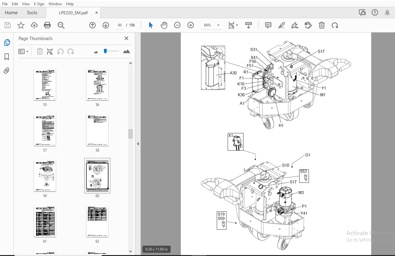
1- Table of contents...........................................................  3
2- Technical data..............................................................  7
	2.1 General tightening torques............................................. 10
		2.1.1 Galvanised, non-oiled bolts...................................... 10
		2.1.2 Untreated, oiled bolts........................................... 10
3- Introduction, maintenance................................................... 11
	3.1 Safety regulations during maintenance work............................. 11
	3.2 Cleaning and washing................................................... 13
		3.2.1 Cleaning the exterior............................................ 13
		3.2.2 Cleaning the motor compartment................................... 13
		3.2.3 Electrical components............................................ 13
	3.3 Safe lifting........................................................... 14
	3.4 Maintenance schedule................................................... 15
	3.5 Lubrication schedule................................................... 20
	3.6 Oil and grease specification........................................... 21
4- Tools....................................................................... 23
	4.1 Super Seal connectors.................................................. 23
	4.2 AMP connectors......................................................... 24
		4.2.1 AMP Connectors, 040 series....................................... 25
	4.3 Molex connectors....................................................... 25
	4.4 Grease guns............................................................ 26
	4.5 Other tools............................................................ 27
5- Fork carriage- 0380......................................................... 29
	5.1 Maintenance............................................................ 29
		5.1.1 Adjusting the play between the fork carriage and body............ 31
6- Engine suspension- 0450..................................................... 33
	6.1 Component parts........................................................ 33
		6.1.1 Component List................................................... 34
7- Electric drive motor - 1760................................................. 35
	7.1 Component parts........................................................ 35
		7.1.1 Dismantling/assembling of motor from truck....................... 36
		7.1.2 Assembling....................................................... 36
	7.2 Service/Repairs........................................................ 37
		7.2.1 Dismantling of motor............................................. 37
		7.2.2 Assembling of motor.............................................. 38
		7.2.3 Cleaning......................................................... 38
	7.3 Technical data......................................................... 39
8- Drive unit/gear - 2550...................................................... 41
	8.1 General................................................................ 41
	8.2 Included components.................................................... 42
	8.3 Disassembly of the drive unit from the truck........................... 44
	8.4 Assembly of the drive unit in the truck................................ 44
	8.5 Oil inspection or changing oil......................................... 45
		8.5.1 Oil inspection/replenishment..................................... 45
		8.5.2 Changing oil..................................................... 45
	8.6 Replacing the gasket ring.............................................. 45
		8.6.1 Disassembly...................................................... 45
		8.6.2 Assembly......................................................... 46
	8.7 Leakage from top cover................................................. 46
9- Electro magnetic brake - 3370............................................... 47
	9.1 Brake LWE180, LWE200, LPE200-6......................................... 47
		9.1.1 Main components.................................................. 47
		9.1.2 Maintenance...................................................... 48
			Exchange of brake disc............................................. 48
	9.2 Brake LPE200-8......................................................... 49
		9.2.1 Main components.................................................. 49
		9.2.2 Maintenance...................................................... 50
			Exchange of brake disc............................................. 50
			Adjustment of gap.................................................. 50
10- Steering system - 4000..................................................... 51
	10.1 Component parts, tiller arm........................................... 51
	10.2 Adjustments........................................................... 52
		10.2.1 Adjusting of brake microswitch.................................. 52
	10.3 Tiller arm handle..................................................... 53
		10.3.1 Dismantling/Assembling.......................................... 54
			Change from ignition key to keyboard (2)........................... 55
			Change from keyboard to ignition key (2)........................... 55
			Changing of signal button/switch (9, 10)........................... 55
			Changing of lift/lowering button (13).............................. 56
			Changing of pushbutton (16)........................................ 56
11- Electrical System - 5000................................................... 57
	11.1 General............................................................... 57
		11.1.1 Software/hardware order numbers................................. 57
		11.1.2 Nomenclature.................................................... 58
	11.2 Electrical equipment overview......................................... 59
		11.2.1 Electric component overview..................................... 61
	11.3 Electrical wiring diagram............................................. 63
		11.3.1 Symbol list..................................................... 63
		11.3.2 Overview........................................................ 64
		11.3.3 Wiring diagram LWE180, LWE 200, LPE200-6........................ 65
		11.3.4 Wiring Diagram LPE200-8......................................... 71
	11.4 Functional description................................................ 82
		11.4.1 Theory of operation............................................. 82
		11.4.2 Spider expansion unit (SEU)..................................... 87
		11.4.3 Hour meter and battery condition................................ 88
		11.4.4 TLS - Truck log system (optional)............................... 89
			General............................................................ 89
			Registration....................................................... 89
			Logging in/out SD16................................................ 89
			Logging in/out S16................................................. 89
			Collision sensor................................................... 90
			Settings........................................................... 90
		11.4.5 ID unit (optional).............................................. 90
		11.4.6 Built-in battery charger (optional)............................. 91
			Technical data..................................................... 91
			Charging........................................................... 92
			Troubleshooting and service........................................ 93
			Adjusting the charger.............................................. 93
	11.5 Parameters & adjustments.............................................. 95
		11.5.1 General......................................................... 95
		11.5.2 Displaying parameters - without the CAN service key............. 95
		11.5.3 Adjusting operator parameters - without the CAN service key..... 96
		11.5.4 Displaying & changing parameters - CAN service key connected.... 96
			Changing a parameter............................................... 97
		11.5.5 List of operator parameters..................................... 98
		11.5.6 Description of operator parameters..............................100
			# 1 - Travel speed, Turtle button (LWE180, LWE200).................100
			# 1 - Creep speed (LPE200-8).......................................100
			# 2 - Maximum travel speed.........................................100
			# 3 - Acceleration.................................................100
			# 4 - Neutral speed reduction......................................100
			# 5 - Logout.......................................................100
		11.5.7 List of Service parameters......................................101
		11.5.8 Description of Service parameter................................103
			# 10 - PIN code....................................................103
			To enter a new PIN-code:...........................................103
			To remove an existing PIN-code:....................................104
			# 14 - Creep speed.................................................104
			#15 - Non-configurable options.....................................104
			Setting Non-configurable options...................................104
			#16 - Configurable option #1.......................................105
			#17 - Configurable option #2.......................................105
			#18 - Configurable option #3.......................................105
			#19 - Configurable option #4.......................................105
			# 20 - Hour meter selection........................................106
			# 21 - Battery size................................................107
			Instructions for verifying parameter setting.......................108
			Instructions for verifying parameter setting.......................109
			# 22 - Brake switch................................................109
			# 25 - Service interval............................................109
			# 28 - Button selection............................................109
			# 39 - Login method and driver parameter access....................110
			Expanded keypad - General..........................................110
			Expanded keypad - Programming......................................111
		11.5.9 Configurable “Option” parameters................................113
			General............................................................113
			Parameter #16 to #19 configurable options..........................114
			Setting Configurable options.......................................114
	11.6 Diagnostic and troubleshooting........................................125
		11.6.1 General.........................................................125
		11.6.2 Fault code history..............................................126
		11.6.3 List of fault codes.............................................126
		11.6.4 Transistor regulator troubleshooting and error codes............139
			General............................................................139
			Transistor regulator errors........................................140
			Resetting errors...................................................141
			Safety.............................................................141
		11.6.5 Built-in Test Function..........................................142
			Digital inputs/outputs test mode...................................143
			Transistor regulator inputs........................................143
			Transistor regulator outputs.......................................143
			Digital input of logic card [A2]...................................144
			Extra functions....................................................144
		11.6.6 Display test mode...............................................145
	11.7 Technical specifications - Curtis 1243................................146
12- Hydraulic/Pneumatik - 6000.................................................147
	12.1 General...............................................................147
	12.2 Hydraulic chart and list of symbols...................................147
		12.2.1 List of Symbols.................................................147
	12.3 Adjustments LWE180....................................................148
		12.3.1 Adjusting the pressure limit valve..............................148
		12.3.2 Tools...........................................................149
	12.4 Adjustments LWE200....................................................150
		12.4.1 Adjusting the pressure limit valve..............................150
	12.5 Hydraulic chart and list of symbols...................................151
		12.5.1 List of Symbols.................................................151
	12.6 Adjusting the pressure limit valve....................................152
13- PowerTrak cylinder - 6680..................................................153
	13.1 Included components...................................................153
	13.2 Disassembling the PowerTrak cylinder and spring guides................154
S.S 06/24