Trusted Business
Verified & Licensed
Virus Free Files
100% Safe Downloads
Secure Payment
SSL Protected
Instant Delivery
Available Immediately
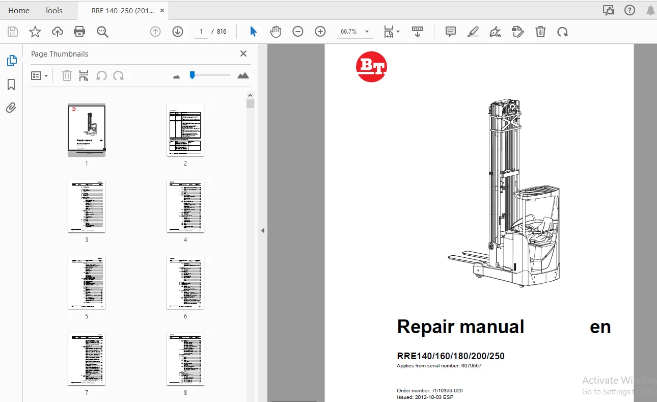
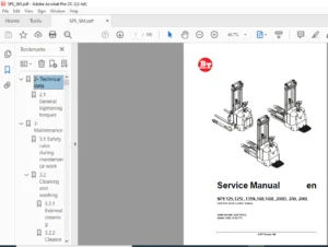
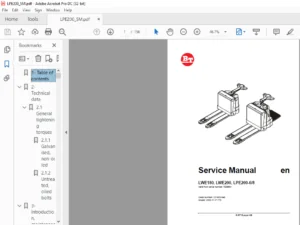
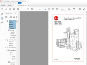
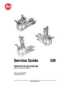
BT Forklift RRE140/160/180/200/250 Repair manual (6070557) – PDF
$31.95
BT Forklift RRE140/160/180/200/250 Repair manual (6070557) – PDF DOWNLOAD
Instant PDF Download
Available immediately
Save to Your Device
Download & keep forever
Antivirus Scanned
100% virus-free
Trusted Worldwide
175,000+ customers
Description
BT Forklift RRE140/160/180/200/250 Repair manual (6070557) – PDF DOWNLOAD
FILE DETAILS:
BT Forklift RRE140/160/180/200/250 Repair manual (6070557) – PDF DOWNLOAD
Language : English
Pages : 816
Downloadable : Yes
File Type : PDF
IMAGES PREVIEW OF THE MANUAL:
TABLE OF CONTENTS:
BT Forklift RRE140/160/180/200/250 Repair manual (6070557) – PDF DOWNLOAD
1 - Contents........................................................................................................  3
2 - General introduction............................................................................................ 19
	2.1 How to use the manual....................................................................................... 19
	2.2 Warning symbols............................................................................................. 20
	2.3 Pictogram................................................................................................... 20
3 - General safety rules............................................................................................ 21
	3.1 Safety while working........................................................................................ 21
	3.2 Electrical system........................................................................................... 22
	3.3 Safe lifting................................................................................................ 23
4 - Descriptions of functions....................................................................................... 25
	4.1 Chassis 0000................................................................................................ 25
		4.1.1 Operator’s cabin (0500)............................................................................... 25
			Versions for cold-store cabs............................................................................ 25
			Emergency exit from the cab............................................................................. 26
		4.1.2 Cab windows (0530).................................................................................... 27
			Electrically heated windows............................................................................. 27
		4.1.3 Operator's seat (0620)................................................................................ 28
			Adjustment:............................................................................................. 28
			Button for seat heater.................................................................................. 28
		4.1.4 Cab heating/ventilation (0630)........................................................................ 29
			Climate control knobs................................................................................... 29
			Ventilation............................................................................................. 29
			Temperature............................................................................................. 29
		4.1.5 Operator protection (0840)............................................................................ 30
			Tilt stops.............................................................................................. 30
			Overhead guard.......................................................................................... 32
	4.2 Motors 1000................................................................................................. 33
		4.2.1 General............................................................................................... 33
		4.2.2 Electric pump motor (1710)............................................................................ 33
			General................................................................................................. 33
			Design.................................................................................................. 33
		4.2.3 Electric steering motor (1730)........................................................................ 35
			General................................................................................................. 35
			Design.................................................................................................. 35
		4.2.4 Fan motor/fan (1740).................................................................................. 36
		4.2.5 Electric drive motor (1760)........................................................................... 37
			General................................................................................................. 37
			Design.................................................................................................. 37
	4.3 Drive gear - 2000........................................................................................... 38
		4.3.1 General............................................................................................... 38
		4.3.2 Design................................................................................................ 39
	4.4 Brake system 3100........................................................................................... 40
		4.4.1 General............................................................................................... 40
			Travel brake............................................................................................ 40
			Parking brake........................................................................................... 40
			Emergency brake......................................................................................... 40
		4.4.2 Drive motor brake (travel brake)...................................................................... 41
			Accelerator released.................................................................................... 41
			Changing the direction of travel........................................................................ 41
		4.4.3 Multiple disc brake, support arm (travel brake)....................................................... 42
			General................................................................................................. 42
			Design.................................................................................................. 42
		4.4.4 Disc brake on the drive motor (parking brake)......................................................... 43
			General................................................................................................. 43
			Design.................................................................................................. 43
	4.5 Steering system 4000........................................................................................ 44
		4.5.1 General............................................................................................... 44
		4.5.2 Design................................................................................................ 44
		4.5.3 Sensor................................................................................................ 45
	4.6 Operator compartment........................................................................................ 46
		4.6.1 Truck control, overview............................................................................... 46
			Right-hand control panel, single control................................................................ 46
			Right-hand control panel, multi-control................................................................. 46
			Emergency off switch.................................................................................... 47
			Steering wheel module................................................................................... 47
			Pedals.................................................................................................. 48
		4.6.2 Single-function controls.............................................................................. 49
		4.6.3 Multi-function controls............................................................................... 50
		4.6.4 Central Information Display - CID..................................................................... 51
			Navigation.............................................................................................. 51
			LED symbols............................................................................................. 54
			Information symbols..................................................................................... 55
			Operator parameter symbols - Overview................................................................... 56
			Blocking symbols - Overview............................................................................. 57
			Service functions....................................................................................... 59
			Calibration functions................................................................................... 61
			Automatic calibration of lowering valve................................................................. 62
			Configuration functions................................................................................. 64
			Other functions......................................................................................... 67
		4.6.5 Load Information Display - LID (option)............................................................... 69
			LED symbols............................................................................................. 69
			Symbols in the display part............................................................................. 70
	4.7 sensors and sensors (5800).................................................................................. 71
		4.7.1 Inductive sensors..................................................................................... 71
		4.7.2 Position sensor....................................................................................... 71
		4.7.3 Magnetic sensor....................................................................................... 72
	4.8 Operation and connection sequences.......................................................................... 73
	4.9 Functions...................................................................................................106
		4.9.1 General overview......................................................................................106
			Terminology.............................................................................................106
			Components..............................................................................................106
		4.9.2 MCU - main control unit...............................................................................107
			General.................................................................................................107
			Downloading software....................................................................................107
			System communication....................................................................................107
		4.9.3 ACT/ACH transistor regulators.........................................................................108
			General.................................................................................................108
		4.9.4 Start-up..............................................................................................108
		4.9.5 Shutdown..............................................................................................109
		4.9.6 Driving...............................................................................................109
			Introduction............................................................................................109
			Acceleration and speed reduction........................................................................109
			Reversing...............................................................................................110
			Brake...................................................................................................110
			Travel speed............................................................................................111
		4.9.7 OTP...................................................................................................112
			Travel speed reduction - steering angle.................................................................112
			Travel speed reduction - extension of reach carriage....................................................112
			Speed reduction - main lift range.......................................................................112
			Prevention of lifting/lowering of the forks.............................................................112
			Reduced extension speed.................................................................................112
		4.9.8 Guide.................................................................................................113
			Steering position control...............................................................................113
			Steering speed..........................................................................................113
			Steering reference......................................................................................114
			Travel speed limitation.................................................................................114
			Compass rose............................................................................................114
		4.9.9 Hydraulic system......................................................................................115
			Definitions.............................................................................................115
			Controls................................................................................................115
			Lift....................................................................................................115
			Reach movement..........................................................................................116
			Lift height limitation..................................................................................116
			Maximum height limitation...............................................................................116
			Auxiliary/Extra functions (option)......................................................................117
	4.10 Height preselector, description of function................................................................118
		4.10.1 Using the height preselector.........................................................................118
		4.10.2 Symbols..............................................................................................118
		4.10.3 Buzzer...............................................................................................118
		4.10.4 Height preselector levels............................................................................119
		4.10.5 Level selection......................................................................................119
		4.10.6 Height programming...................................................................................120
		4.10.7 Height preselector and TruckCom......................................................................121
		4.10.8 Lifting/lowering movement............................................................................121
		4.10.9 Parameter settings braking at height preselector.....................................................122
	4.11 Hydraulic system 6000......................................................................................123
		4.11.1 General..............................................................................................123
		4.11.2 Tank.................................................................................................123
		4.11.3 Filter...............................................................................................123
			Return filter...........................................................................................123
			Dehumidification filter.................................................................................123
		4.11.4 Hydraulic pump.......................................................................................124
		4.11.5 Valve unit...........................................................................................124
			Main valve block........................................................................................124
			Second valve block......................................................................................125
		4.11.6 Cylinders............................................................................................126
			Main lift cylinders.....................................................................................126
			Free-lift cylinder......................................................................................126
			Cylinders for the reach movement, cabin tilt, sideshift and fork tilt...................................126
		4.11.7 Lift and lowering function...........................................................................127
			Lifting and lowering of free lift.......................................................................127
			Transition from free lift to main lift..................................................................127
			Lifting and lowering of main lift.......................................................................127
			Reach movement, in and out..............................................................................127
			Simultaneous operation of mast lift and reach movement..................................................128
		4.11.8 Extra functions......................................................................................128
		4.11.9 Cabin tilt (RRE Ergo)................................................................................128
			Hydraulic priority system...............................................................................128
			Cabin tilt (RRE Ergo) during servicing..................................................................129
			Cabin tilt in the event of hydraulic or electrical power loss...........................................129
	4.12 Mast 7000..................................................................................................130
		4.12.1 Mast and reach carriage..............................................................................130
	4.13 Lifting devices............................................................................................131
		4.13.1 Fork extensions......................................................................................131
		4.13.2 Telescopic forks.....................................................................................131
	4.14 Accessories 9000...........................................................................................133
		4.14.1 Radio equipment......................................................................................133
		4.14.2 Extra lighting.......................................................................................133
		4.14.3 Extra warning lights/alarm...........................................................................134
		4.14.4 Turn signal lights...................................................................................134
		4.14.5 Movement alarm.......................................................................................135
		4.14.6 Positioning/TV equipment.............................................................................136
		4.14.7 Extra electrical equipment...........................................................................138
		4.14.8 Other extra equipment................................................................................139
			Fork spacers............................................................................................139
			Load rest...............................................................................................140
			E-bar...................................................................................................141
			Flashlight..............................................................................................142
5 - Parameters......................................................................................................143
	5.1 General.....................................................................................................143
	5.2 Displaying/changing parameters..............................................................................143
	5.3 Operator parameters.........................................................................................144
		5.3.1 Overview..............................................................................................144
		5.3.2 Connection to logged-in operator......................................................................145
		5.3.3 Description...........................................................................................146
			Parameter 1 - Steering..................................................................................146
			Parameter 2, 3 - Maximum travel speed...................................................................148
			Parameters 4 and 5 - Acceleration/Retardation...........................................................148
			Parameter 6 - Cab tilt..................................................................................148
	5.4 General service parameters..................................................................................149
		5.4.1 Overview..............................................................................................149
		5.4.2 Description...........................................................................................149
			Parameter 101/104 - Service/Logout......................................................................149
			Parameter 105/106/114/115/117 (Travel alarms 1 and 2)...................................................150
			Parameter 107/108 - Battery.............................................................................152
			Parameter 109/110/111/112 - Collision sensor............................................................156
			Parameter 113 (shunt value).............................................................................157
			Parameter 116 (Door on cold store cab)..................................................................158
		5.4.3 Service parameters, travel functions..................................................................159
		5.4.4 Overview..............................................................................................159
		5.4.5 Description...........................................................................................159
			Parameter 201 - Deceleration when reversing.............................................................159
			Parameter 202/203/204 - Adjusting erroneous, maximum travel speeds......................................160
			Parameter 205/206/207 - Adjusting erroneous, maximum travel speeds......................................160
			Parameter 208 - Creep speed in travel direction control.................................................161
			Parameter 209/210 - Reduced maximum travel speed above a certain lift height............................161
			Parameter 211/212 - Reduced maximum travel speed with a certain reach length............................162
			Parameter 213 - Permanently reduced maximum travel speed................................................162
			Parameter 214 - Adjusting the maximum travel speed in main lift range...................................162
	5.5 Service parameters, hydraulics..............................................................................163
		5.5.1 Overview..............................................................................................163
		5.5.2 Description...........................................................................................166
			Parameter 301/302/303/304 - Extra valve function........................................................166
			Parameter 305/306/307/308 - Max. oil pressure through valve Q8..........................................168
			Parameter 313/314/315/316 - Closing time................................................................169
			Parameter 317/318/319/320 - Max. oil flow through valve Q8..............................................169
			Parameter 321/322/323/324 - Max. oil flow through valve Q9..............................................170
			Parameter 325/326/327/328 - Opening/closing time valve Q8...............................................170
			Parameter 329/330/331/332 - Opening/closing time valve Q9...............................................171
			Parameter 341/342 - Reducing the lifting/lowering speed.................................................171
			Parameter 343 - Reduction of reach speed................................................................172
			Parameter 344 - Reduction of fork lowering speed before floor level.....................................172
			Parameter 345- Lift/lower sensitivity...................................................................172
			Parameter 347/348 - Prevent the lifting/lowering of forks...............................................173
			Parameter 349 - Fork weight.............................................................................173
			Parameter 350 - Multi-function..........................................................................174
			Parameters 358/359/360 - Deactivation of hydraulic functions............................................175
			Parameters 361/362/363/364/365 /366 - Function related, maximum lift/lowering speeds....................176
			Parameter 367/368 - Fork limit for deactivating the extension of the fork carriage and for sideshift....177
			Parameter 369 through 379 - Height preselector..........................................................178
			Parameter 380 through 386 - Lift height limitations.....................................................180
			Parameters 387 through 393 - Configuration of lift height limitations...................................180
			Parameters 395/396/397 - Function-related, maximum lift heights.........................................181
			Parameters 398/399 - Operator profile dependent, maximum lift heights...................................182
	5.6 Service parameters, CID.....................................................................................183
		5.6.1 Overview..............................................................................................183
		5.6.2 Description...........................................................................................184
			Parameter 503 - Login method............................................................................184
			Parameter 504/505/506/507 - Smart Access................................................................184
			Parameters 508/509/512/513/514 - CID configuration......................................................189
			Parameter 510/511 - Height pre-selector.................................................................191
	5.7 Service parameters, General Function Unit GFU...............................................................192
	5.8 General factory parameters..................................................................................193
		5.8.1 Overview..............................................................................................193
		5.8.2 Description...........................................................................................194
			Parameter 1001 - Truck type.............................................................................194
			Parameter 1002 - (Drive motor)..........................................................................194
			Parameter 1003 - Pedal type.............................................................................194
			Parameter 1004 - Steering servo.........................................................................195
			Parameter 1005 - Pump motor.............................................................................195
			Parameter 1006 - Hydraulic pump.........................................................................195
			Parameter 1007 - Activation of hydraulic levers.........................................................196
			Parameter 1008 - Mast type..............................................................................196
			Parameter 1009 - Height indication......................................................................197
			Parameter 1010 - Weight indication......................................................................197
	5.9 Factory parameters, activation of options...................................................................198
		Parameter 1115 (Steering angle).............................................................................200
		Parameter 1116 (Extended mast)..............................................................................200
		Parameter 1117 (Weight of load and fork height).............................................................201
		Parameter 1118 (Main lift range)............................................................................201
	5.10 Factory parameters, calibration............................................................................203
6 - Installation....................................................................................................207
	6.1 Transporting the truck......................................................................................207
		Method 1....................................................................................................207
		Method 2....................................................................................................207
	6.2 Initial operation...........................................................................................208
		6.2.1 Tool..................................................................................................208
		6.2.2 Battery...............................................................................................208
			Placing the battery.....................................................................................208
			Battery parameters......................................................................................209
		6.2.3 Mast, fitting.........................................................................................209
		6.2.4 Parameters on initial operation.......................................................................209
			Load indicator..........................................................................................209
			Ergo cabin..............................................................................................210
			Cold store cabin........................................................................................210
		6.2.5 Parameters for optional equipment.....................................................................211
			Height measurement (option).............................................................................211
			Travel speed limitation, height-dependent...............................................................211
			Travel speed limitation, reach movement dependent.......................................................211
			Travel speed limitation, parameter-dependent............................................................212
			Collision sensor (BT)...................................................................................212
		6.2.6 Test driving..........................................................................................212
7 - Maintenance.....................................................................................................215
	7.1 Introduction, maintenance...................................................................................215
	7.2 Safety precautions for maintenance work.....................................................................216
	7.3 Checks for cracks...........................................................................................218
		7.3.1 Visual inspection.....................................................................................218
		7.3.2 Crack detection.......................................................................................219
			Crack detection with liquid penetrants..................................................................219
			Crack detection with magnetic yoke......................................................................219
	7.4 Periodic maintenance........................................................................................220
		7.4.1 Every 500 B-hours/180 days............................................................................220
		7.4.2 Every 1000 B-hours/360 days...........................................................................222
		7.4.3 Every 2000 B-hours/720 days...........................................................................227
		7.4.4 Every 3000 B-hours/1080 days..........................................................................227
		7.4.5 Every 5000 B-hours/1800 days..........................................................................229
		7.4.6 Annual status inspection..............................................................................229
	7.5 Maintenance instructions....................................................................................230
		7.5.1 Cleaning and washing..................................................................................230
			High-pressure washers...................................................................................230
			Degreasing agents.......................................................................................230
			Cleaning the truck exterior.............................................................................230
			Cleaning the chain......................................................................................231
			Cleaning the motor compartment..........................................................................231
			Electrical components...................................................................................231
8 - Troubleshooting.................................................................................................233
	8.1 Abbreviations used in this section..........................................................................233
	8.2 Truck help functions........................................................................................233
		8.2.1 Error log menu........................................................................................233
			Description.............................................................................................233
			Access..................................................................................................233
		8.2.2 Error information menu................................................................................234
			Description.............................................................................................234
			Access..................................................................................................234
		8.2.3 Diagnostic screens....................................................................................234
			Access..................................................................................................234
			State 1 - Voltage from the control console levers.......................................................235
			State 2 - Digital signals from the truck control to CID.................................................236
			State 3 - Voltage from control/sensor to MCU............................................................237
			State 4 - Digital input signals to MCU..................................................................238
			State 5 - Digital output signals from MCU...............................................................240
			State 6 - PWM output signals from MCU...................................................................241
			State 7 - FCU (not used)................................................................................241
			State 8 - FCU (not used)................................................................................241
			State 9 - GFU (not used)................................................................................241
			State 10 - GFU (not used)...............................................................................241
			State 11 - Temperature signals..........................................................................242
			State 12 - Voltage levels...............................................................................242
			State 13 - Travel information...........................................................................243
			State 14 - Steering information.........................................................................244
			State 15 - Lift/lowering information....................................................................245
			Stage 16 - Reach movement information...................................................................246
			Stage 17 - Hydraulic information........................................................................247
			State 18 - VNA (not used)...............................................................................248
			State 19 - Pressure sensor for free and main lifts......................................................248
	8.3 Initial troubleshooting.....................................................................................249
	8.4 Troubleshooting using catch symbol..........................................................................250
	8.5 Troubleshooting using error codes...........................................................................258
		8.5.1 CID, warnings and errors..............................................................................260
		8.5.2 MCU and other warnings and errors.....................................................................264
		8.5.3 Drive system error....................................................................................274
		8.5.4 Hydraulic system error................................................................................287
		8.5.5 Steering system, warnings and errors..................................................................320
		8.5.6 GFU, warnings and errors..............................................................................327
	8.6 Troubleshooting without indications.........................................................................329
		8.6.1 Mechanical brake (3000)...............................................................................329
		8.6.2 Steering (4000).......................................................................................329
		8.6.3 Telescopic forks......................................................................................330
		8.6.4 Log on was normal, but one or several functions cannot be used........................................331
9 - Frame/Chassis 0000..............................................................................................333
	9.1 General.....................................................................................................333
	9.2 Motor hood (0340)...........................................................................................333
		9.2.1 Opening the motor compartment.........................................................................333
			RRE 140-RRE 250.........................................................................................333
			To open the motor compartment:..........................................................................333
			To close the motor compartment:.........................................................................333
			Replacing the motor hood................................................................................334
			Adjustment of motor hood................................................................................334
	9.3 Battery compartment components (0390).......................................................................336
		9.3.1 Adjusting the battery bed.............................................................................336
	9.4 Operator's cab (0500).......................................................................................337
		9.4.1 Cab tilting RRE 140 - 250 Ergo........................................................................337
		9.3.1 Cab windows (0530)....................................................................................338
			Fitting a window........................................................................................338
		9.3.2 Cab door (0550).......................................................................................340
			Disassembly of the door lock............................................................................340
			Tools required..........................................................................................341
			Method..................................................................................................341
			Disassembly of the lock device..........................................................................342
	9.4 Operator compartment (0600).................................................................................344
		9.4.1 Operator's seat (0620)................................................................................344
			Disassembling the entire seat...........................................................................344
			Replacing the seat switch...............................................................................345
			Replacing the back rest.................................................................................346
			Replacing the chair seat................................................................................347
			Replacing the seat heater switch........................................................................347
		9.4.2 Cab heating/ventilation (0630)........................................................................348
			Replacing the air filter on the cold store cabin:.......................................................348
			Removing the fan and heater.............................................................................349
			Replacing the potentiometers............................................................................353
		9.4.3 Internal fittings (0680)..............................................................................355
		9.4.4 Disassembling/assembling the floor plate, B version 0680..............................................356
	9.5 Safety equipment (0800).....................................................................................358
		9.5.1 Checking the overhead guard (0810)....................................................................358
		9.5.2 Adjusting the tilt stops (0840).......................................................................359
10 - Motors 1000....................................................................................................361
	10.1 Motor sensors..............................................................................................361
		10.1.1 Temperature sensor...................................................................................361
			Retrofitting an external temperature sensor.............................................................362
		10.1.2 Replacing the motor speed sensor.....................................................................362
	10.2 Pump motor (1710)..........................................................................................363
		10.2.1 General..............................................................................................363
			The pump motor dismantled...............................................................................363
		10.2.2 Replacing the bearing on the pump motor..............................................................364
			Dismantling the pump motor..............................................................................364
			Reassembling the pump motor.............................................................................366
	10.3 Steering motor and steering unit (1730)....................................................................367
		10.3.1 General..............................................................................................367
		10.3.2 Layout of the flange holes...........................................................................367
		10.3.3 Removing the steering motor from the truck...........................................................368
		10.3.4 Fitting the steering motor in the truck..............................................................368
	10.4 Fan motor/fan (1740).......................................................................................369
		10.4.1 General..............................................................................................369
		10.4.2 Replacing the frequency converter cooling fan........................................................369
			Standard truck..........................................................................................369
			Ergo truck..............................................................................................369
		10.4.3 Replacing the motor compartment cooling fan..........................................................371
	10.5 Drive motor (1760).........................................................................................372
		10.5.1 General..............................................................................................372
			The drive motor dismantled..............................................................................372
		10.5.2 Removing the drive motor from the truck..............................................................373
		10.5.3 Dismantling the drive motor..........................................................................375
		10.5.4 Cleaning.............................................................................................377
		10.5.5 Assembling the drive motor...........................................................................378
		10.5.6 Fitting the drive motor in the truck.................................................................380
11 - Drive gear 2000................................................................................................383
	11.1 General....................................................................................................383
	11.2 Repair- and serviceability.................................................................................383
	11.3 Measures...................................................................................................384
		11.3.1 Checking the oil level...............................................................................384
		11.3.2 Oil change...........................................................................................385
			Oil refill table........................................................................................385
		11.3.3 Leakage from the bottom cap..........................................................................386
		11.3.4 Replacing the drive gear.............................................................................387
			Special tools...........................................................................................387
			Exposing the drive gear.................................................................................387
			Removing a drive motor from the truck...................................................................387
			Removing a steering motor from the truck................................................................387
			Removing the drive gear from the truck..................................................................388
			Fit the drive gear back in the truck....................................................................390
			Placing the steering motor in the truck.................................................................391
			Placing the drive motor in the truck....................................................................391
			Concluding work.........................................................................................391
12 - Brake and wheel 3000...........................................................................................393
	12.1 Travel brake system (3100).................................................................................393
		12.1.1 Removing the support arm's multiple disc brake.......................................................393
		12.1.2 Dismantling the multiple disc brake..................................................................393
			Inspection..............................................................................................394
			Adjusting play..........................................................................................394
			Assembling the multiple disc brake......................................................................395
		12.1.3 Installing the multiple disc brake in the truck......................................................395
		12.1.4 Checking the wheel brake's brake force...............................................................396
	12.2 Parking brake (3300).......................................................................................397
		12.2.1 General..............................................................................................397
		12.2.2 Emergency release of the parking brake...............................................................398
		12.2.3 Checking the brake force.............................................................................398
		12.2.4 Removing the parking brake from the truck............................................................399
			Dismantling and checking for wear.......................................................................400
			Adjusting the air gap...................................................................................402
		12.2.5 Installing the parking brake in the truck............................................................404
	12.3 Drive wheel (3530).........................................................................................405
		12.3.1 General..............................................................................................405
		12.3.2 Removing the drive wheel from the truck..............................................................405
		12.3.3 Installing the drive wheel on the truck..............................................................405
	12.4 Wheel bolt (3530)..........................................................................................406
		General.....................................................................................................406
		12.4.1 Replacing wheel bolts................................................................................406
	12.5 Support arm wheel (3550)...................................................................................407
		12.5.1 Removing the support arm wheel from the truck........................................................407
		12.5.2 Replacing a wheel bearing - braked wheel (A).........................................................408
		12.5.3 Replacing a wheel bearing - unbraked wheel (B).......................................................409
		12.5.4 Fitting the support arm wheel to the truck...........................................................410
		12.5.5 Wheel wear and tear..................................................................................411
13 - Steering system 4000...........................................................................................413
	13.1 Electric steering wheel (4310).............................................................................413
		13.1.1 General..............................................................................................413
		13.1.2 Replacing the pulse transducer on the steering wheel module..........................................413
		13.1.3 Removing the operating console from the truck........................................................414
		13.1.4 Replacing the wiring harness in the operating console................................................416
		13.1.5 Fitting the operating console in the truck...........................................................418
	13.2 Steering reference sensor (4350)...........................................................................419
		General.....................................................................................................419
		13.2.1 Replacing the reference transducer [B17].............................................................419
	13.3 Steering bearings (4380)...................................................................................420
		13.3.1 Removing a steering bearing from the drive gear......................................................420
		13.3.2 Fitting a steering bearing on the drive gear.........................................................420
14 - Electrical system 5000.........................................................................................423
	14.1 Battery (5110).............................................................................................423
		14.1.1 Battery recommendation...............................................................................423
			Exide gel batteries (e.g. Sonnenschein).................................................................423
			Hawker Evolution gel batteries..........................................................................423
		14.1.2 Battery installation.................................................................................424
			Replacement/installation of battery.....................................................................424
			Procedure without battery changing table................................................................425
			Procedure with battery changing table...................................................................425
	14.2 LID (5200).................................................................................................426
		14.2.1 Replacing the LID....................................................................................426
		14.2.2 Replacing the LID cold store cab.....................................................................427
	14.3 Replacing pedals (5300)....................................................................................428
		14.3.1 Accelerator and brake pedal..........................................................................428
		14.3.2 Safety pedal.........................................................................................428
	14.4 Control console (5510).....................................................................................429
		14.4.1 General..............................................................................................429
		14.4.2 Replacement/installation of a control................................................................429
		14.4.3 Replacing the multi-function control.................................................................430
			Replacing the multi-function control's buttons..........................................................430
		14.4.4 Removing the control console from the truck..........................................................431
		14.4.5 Replacing the access card's circuit board............................................................432
		14.4.6 Dismantling the control console......................................................................434
			Installing an extra push button.........................................................................436
			Replacing the travel direction selector with signal button..............................................436
			Replacing the display...................................................................................437
		14.4.7 Assembling the control console.......................................................................437
		14.4.8 Fitting the control console in the truck.............................................................438
	14.5 Magnetic sensor (5850).....................................................................................440
		General.....................................................................................................440
		14.5.1 Replacing the magnetic sensor [B47]..................................................................440
		14.5.2 Reference magnet.....................................................................................441
	14.6 Parameter settings.........................................................................................442
		14.6.1 Configuration menu...................................................................................442
			Calendar/hour counter menu..............................................................................442
			Parameter menu (PAR)....................................................................................442
			Setting operator parameters.............................................................................443
	14.7 PIN menu...................................................................................................444
		14.7.1 Menu for activating a PIN block......................................................................445
		14.7.2 Menu for programming a PIN (P).......................................................................445
	14.8 Calibrations...............................................................................................446
		14.8.1 Calibrating the hydraulic function control...........................................................446
		14.8.2 Height measurement/reach movement length calibration.................................................447
			Calibrating height measurement (option).................................................................448
		14.8.3 Valve calibration....................................................................................451
			Lift valve calibration..................................................................................451
			Lowering valve calibration with height indication.......................................................453
			Lowering calibration without height indication..........................................................455
			Reach movement valve calibration........................................................................457
			Calibration of the Ergo cab.............................................................................460
		14.8.4 Weight calibration...................................................................................461
			Calibrating the weight indicator........................................................................461
	14.9 Replacing the wiring harness...............................................................................463
	14.10 main computer unit MCU (A5)...............................................................................464
		14.10.1 Installing a new card in the truck..................................................................464
		14.10.2 Voltage supply......................................................................................465
		14.10.3 Battery negative....................................................................................465
		14.10.4 Internal status monitoring..........................................................................465
		14.10.5 Resetting the battery indicator.....................................................................465
15 - Hydraulic system 6000..........................................................................................467
	15.1 Hydraulic hygiene..........................................................................................467
		15.1.1 Washing..............................................................................................467
		15.1.2 Packaging............................................................................................467
		15.1.3 Handling.............................................................................................467
		15.1.4 Storage..............................................................................................468
		15.1.5 Work procedures......................................................................................468
	15.2 Hydraulic unit (6100)......................................................................................469
		15.2.1 Hydraulic tank, emptying.............................................................................470
		15.2.2 Hydraulic system, bleeding...........................................................................471
		15.2.3 Filter...............................................................................................472
			Overview................................................................................................472
			Filter replacement (air and oil)........................................................................473
		15.2.4 Remove the pump motor from the truck.................................................................475
		15.2.5 Replacing the hydraulic pump.........................................................................476
		15.2.6 Fitting the pump motor in the truck..................................................................477
	15.3 Main valve (6210)..........................................................................................478
		15.3.1 Emergency lowering of forks..........................................................................478
		15.3.2 Replacing the main valve block.......................................................................480
		15.3.3 Replacing the lifting/lowering valves................................................................482
			Overview................................................................................................482
			Method..................................................................................................483
		15.3.4 Adjusting the maximum opening pressure...............................................................486
	15.4 Hydraulic connections (6230)...............................................................................488
		15.4.1 Tightening torques for hydraulic connections.........................................................488
			Tapered coupling with O-ring............................................................................488
			Tredo sealing...........................................................................................489
			Pipe coupling...........................................................................................490
		15.4.2 Quick change connector...............................................................................492
	15.5 Hydraulic system, mast (6300)..............................................................................494
		15.5.1 Mast-mounted hose reel (6370)........................................................................494
			General.................................................................................................494
		15.5.2 Fitting the hose reel................................................................................494
			Spring preloading (turns)...............................................................................494
		15.5.3 Checks after fitting.................................................................................495
	15.6 Main lift cylinder 6610....................................................................................496
		General.....................................................................................................496
		15.6.1 Overview.............................................................................................497
			Cylinder nomenclature...................................................................................497
			Nomenclature for cylinder head..........................................................................498
			Nomenclature for piston.................................................................................498
		15.6.2 Removing the air cylinder from the mast..............................................................499
		15.6.3 Replacing the hose rupture valve.....................................................................500
		15.6.4 Dismantling the cylinder.............................................................................502
		15.6.5 Dismantling the piston...............................................................................504
			Method..................................................................................................504
		15.6.6 Dismantling the cylinder head........................................................................504
		15.6.7 Fitting the cylinder head seals......................................................................506
		15.6.8 Fitting the piston seals.............................................................................508
		15.6.9 Assembling the cylinder..............................................................................510
		15.6.10 Assembling cylinder in the mast.....................................................................512
	15.7 Free lift cylinder (6620)..................................................................................514
		General.....................................................................................................514
		15.7.1 Overview.............................................................................................515
			Cylinder nomenclature...................................................................................515
			Nomenclature for cylinder head..........................................................................516
			Nomenclature for piston.................................................................................516
		15.7.2 Removing the free lift cylinder from the truck.......................................................517
		15.7.3 Replacing the hose rupture valve, free lift cylinder.................................................517
		15.7.4 Dismantling the cylinder.............................................................................518
			Tools required..........................................................................................519
			Method..................................................................................................519
		15.7.5 Dismantling the piston...............................................................................519
			Method..................................................................................................519
		15.7.6 Dismantling the cylinder head........................................................................520
			Method..................................................................................................520
		15.7.7 Fitting the cylinder head seals......................................................................521
			Method..................................................................................................521
		15.7.8 Fitting the piston seals.............................................................................522
			Method..................................................................................................523
		15.7.9 Assembling the cylinder..............................................................................524
		15.7.10 Assembling the free lift cylinder in the mast.......................................................526
	15.8 Reach cylinder (6650)......................................................................................527
		15.8.1 General..............................................................................................527
		15.8.2 Removing the reach cylinder from the truck...........................................................527
		15.8.3 Fitting the reach cylinder in the truck..............................................................528
	15.9 Fork tilt cylinder (6660)..................................................................................529
		15.9.1 General..............................................................................................529
		15.9.2 Remove the tilt cylinder from the truck..............................................................530
			Mast with valve on the fork carriage:...................................................................530
			Mast without valve on the fork carriage:................................................................532
		15.9.3 Fit the tilt cylinder in the truck...................................................................534
			Mast without valve on the fork carriage:................................................................536
	15.10 Cab tilt cylinder (6660)..................................................................................538
		15.10.1 General.............................................................................................538
		15.10.2 Overview............................................................................................538
			Cylinder nomenclature...................................................................................538
			Nomenclature for cylinder head..........................................................................539
			Nomenclature for piston.................................................................................539
		15.10.3 Dismantling the cylinder............................................................................540
		15.10.4 Dismantling the piston rod..........................................................................542
		15.10.5 Dismantling the cylinder head.......................................................................544
		15.10.6 Fitting the cylinder head seals.....................................................................546
		15.10.7 Mounting the piston rod.............................................................................548
		15.10.8 Assembling the cylinder.............................................................................550
	15.11 Sideshift cylinder (6670).................................................................................552
		15.11.1 General.............................................................................................552
		15.11.2 Overview............................................................................................553
			Cylinder nomenclature...................................................................................553
			Nomenclature for cylinder head..........................................................................554
			Nomenclature for piston.................................................................................554
		15.11.3 Dismantling the cylinder from the truck.............................................................555
		15.11.4 Dismantling the cylinder............................................................................556
		15.11.5 Dismantling the piston rod..........................................................................558
		15.11.6 Dismantling the cylinder head.......................................................................560
		15.11.7 Fitting the cylinder head seals.....................................................................562
		15.11.8 Mounting the piston rod.............................................................................564
		15.11.9 Assembling the cylinder.............................................................................566
		15.11.10 Refitting the cylinder in the truck................................................................567
16 - Mast/Lift system 7000..........................................................................................569
	16.1 Main mast 1.6-2.5 t (7100).................................................................................569
		16.1.1 Replacing the full mast..............................................................................569
		16.1.2 Removing the mast from the truck.....................................................................570
		16.1.3 Adjusting mast play..................................................................................573
			General.................................................................................................573
			Preparations............................................................................................573
			Adjusting lateral play..................................................................................576
			Adjustment of radial play...............................................................................577
			Adjusting the damper parts..............................................................................577
			Adjusting the damper plate..............................................................................578
			Refitting the mast......................................................................................578
		16.1.4 Replacing the mast damper plates.....................................................................579
		16.1.5 Placing the mast on the truck........................................................................580
	16.2 Main lift chain system (7120)..............................................................................584
		16.2.1 General..............................................................................................584
		16.2.2 Checking the chain...................................................................................584
			Noise...................................................................................................584
			Surface rust............................................................................................584
			Rusty links.............................................................................................584
			Stiff links.............................................................................................585
			Bolt rotation...........................................................................................585
			Loose bolts.............................................................................................585
			Outline wear............................................................................................586
			Stretching..............................................................................................587
			Damage..................................................................................................587
			Damaged plates..........................................................................................588
			Damaged bolts...........................................................................................588
			Dirty chain.............................................................................................588
		16.2.3 Lubricating the chain................................................................................588
		16.2.4 Main lift chain system, adjusting the fork-to-floor distance.........................................589
	16.3 Reach carriage (7190)......................................................................................590
		16.3.1 Adjusting radial play in the reach carriage..........................................................590
		16.3.2 Adjusting axial play in the reach carriage...........................................................592
	16.4 Lifting devices (7400).....................................................................................593
		16.4.1 Forks................................................................................................593
			General.................................................................................................593
			Inspection..............................................................................................593
			Inspection intervals....................................................................................593
			Surface cracks..........................................................................................593
			Difference in height between the fork tips..............................................................594
			Position lock...........................................................................................594
			Readability of the markings.............................................................................594
			Fork blades and back of fork carriage...................................................................594
			Mounting fixtures on the fork...........................................................................594
		16.4.2 Forks, repairs and testing...........................................................................595
			Repairs.................................................................................................595
			Testing the yield point.................................................................................595
			Fork....................................................................................................595
	16.5 Fork carriage..............................................................................................596
		16.5.1 Checking the fork carriage’s wear strip..............................................................596
		16.5.2 Lubricating the fork carriage........................................................................597
	16.6 Fork spread unit...........................................................................................598
		16.6.1 Servicing the fork spread unit.......................................................................598
			Replacing bearings......................................................................................599
			Roller replacement......................................................................................599
	16.7 Fork extensions with adjustable fork length................................................................600
	16.8 Manual telescopic forks....................................................................................602
		16.8.1 Installation.........................................................................................602
		16.8.2 Maintenance..........................................................................................603
	16.9 Hydraulic telescopic forks.................................................................................604
		16.9.1 Telescopic forks with separate flow dividers.........................................................605
			Fitting instructions....................................................................................606
			Initial operation of telescopic forks with separate flow dividers.......................................606
		16.9.2 Telescopic forks with integrated flow dividers.......................................................607
			Fitting instructions....................................................................................608
			Initial operation of telescopic forks with integrated flow dividers.....................................608
		16.9.3 Maintenance of telescopic forks......................................................................609
		16.9.4 Dismantling telescopic forks.........................................................................610
		16.9.5 Assembling telescopic forks..........................................................................611
17 - Peripherals - 8000.............................................................................................613
	17.1 Introduction...............................................................................................613
18 - Extra equipment - 9000.........................................................................................615
	18.1 Introduction...............................................................................................615
19 - Appendix “Destruction instructions”............................................................................617
	19.1 General....................................................................................................617
	19.2 Marking of plastics........................................................................................617
		19.2.1 General marking of products and packaging material...................................................617
		19.2.2 Marking according to our standard....................................................................618
			Abbreviations...........................................................................................618
			Marking examples........................................................................................618
	19.3 Pressure vessels...........................................................................................619
		19.3.1 Gas dampers..........................................................................................619
	19.4 Sorting categories.........................................................................................620
20 - Wiring diagram.................................................................................................623
	20.1 Components.................................................................................................623
	20.2 Component location.........................................................................................633
		Figure 1 (Fork carriage)....................................................................................633
		Figure 2 (Chassis wiring harness)...........................................................................634
		Figure 3 (Chassis wiring harness)...........................................................................635
		Figure 4 (Support leg brake)................................................................................636
		Figure 5 (Pedals)...........................................................................................636
		Figure 6 (Motor wiring harness).............................................................................637
		Figure 7 (Reach carriage wiring harness)....................................................................638
		Figure 8 (Level/position meter).............................................................................639
		Figure 9 (seat).............................................................................................640
		Figure 10 (DC/DC)...........................................................................................641
		Figure 11 (Driver position wiring harness)..................................................................642
		Figure 12 (Extra hydraulic function(s)).....................................................................643
		Figure 13 (Travel alarm)....................................................................................644
		Figure 14 (Roof wiring harness).............................................................................645
		Figure 15 (Roof)............................................................................................646
		Figure 16 (Sound system)....................................................................................647
		Figure 17 (Forks camera)....................................................................................648
		Figure 18 (Battery harness).................................................................................649
		Figure 19 (Fuse box)........................................................................................650
		Figure 20 (LID).............................................................................................651
		Figure 21 (Mast wiring harness).............................................................................652
		Figure 22 (Fork carriage wiring harness)....................................................................653
		Figure 23 (Reach carriage wiring harness options)...........................................................654
		Figure 24 (Working light wiring harness)....................................................................655
		Figure 24 (Extra outlet DC).................................................................................656
		Figure 25 (T.W.I.S.)........................................................................................656
		Figure 26 (Shock Switch / Impact Manager)...................................................................657
		Figure 27 (Heated windows CC)...............................................................................658
		Figure 28 (Cabling driver position CC)......................................................................659
		Figure 29 (Heater CC).......................................................................................660
		Figure 30 (Cab heater wiring harness CC)....................................................................661
		Figure 31 (Safety switch for door CC).......................................................................662
		Figure 32 (Cab tilt wiring harness).........................................................................662
		Figure 33 (Control panel)...................................................................................663
		Figure 34 (Control panel)...................................................................................664
		Figure 35 (Steering arm)....................................................................................665
		Figure 36 (MCU).............................................................................................666
		Figure 37 (Control motor)...................................................................................667
		Figure 38 (Main valve block)................................................................................668
	20.3 Cable connections and pole bolts...........................................................................670
		20.3.1 ACT/ACH transistor regulators........................................................................670
		20.3.2 Connections to CID...................................................................................672
		20.3.3 Connections on the MCU...............................................................................674
	20.4 Fuse box A9................................................................................................676
	20.5 Overview...................................................................................................677
	20.6 Details up to and including serial no. 6206800.............................................................682
	20.7 Detailed diagram cold-store cab............................................................................707
	20.8 Details up to and including serial no. 6206800.............................................................732
	20.9 Details cold store cab starting with 6206800...............................................................758
21 - Hydraulics schematics..........................................................................................785
	21.1 Main valve unit............................................................................................785
		21.1.1 RRE Std..............................................................................................785
		21.1.2 RRE Ergo.............................................................................................786
	21.2 Hydraulics schematics......................................................................................787
		21.2.1 Schematics designations..............................................................................787
		21.2.2 List of symbols......................................................................................788
		21.2.3 Wiring diagrams RRE/RRE Ergo.........................................................................789
22 - Tools..........................................................................................................795
	22.1 AMP connectors.............................................................................................795
	22.2 MQS contacts...............................................................................................796
	22.3 CPC contacts...............................................................................................798
	22.4 Miscellaneous tools........................................................................................799
23 - Appendix “Service data and grease specifications”..............................................................803
	23.1 General tightening torques.................................................................................803
		23.1.1 Galvanised non-oiled bolts...........................................................................803
		23.1.2 Untreated oiled bolts................................................................................804
	23.2 Oil and grease specification...............................................................................805
24 - Technical data.................................................................................................807
S.S 06/24