Trusted Business
Verified & Licensed
Virus Free Files
100% Safe Downloads
Secure Payment
SSL Protected
Instant Delivery
Available Immediately
BT Prime-Mover CSX10/20/30/40 Master Service Manual – PDF DOWNLOAD
$37.95
BT Prime-Mover CSX10/20/30/40 Master Service Manual – PDF DOWNLOAD
Instant PDF Download
Available immediately
Save to Your Device
Download & keep forever
Antivirus Scanned
100% virus-free
Trusted Worldwide
175,000+ customers
Description
BT Prime-Mover CSX10/20/30/40 Master Service Manual – PDF DOWNLOAD
FILE DETAILS:
BT Prime-Mover CSX10/20/30/40 Master Service Manual – PDF DOWNLOAD
Language : English
Pages : 1066
Downloadable : Yes
File Type : PDF
304959-000 1996_October
304959-000 1997_October
304959-000 2002_April
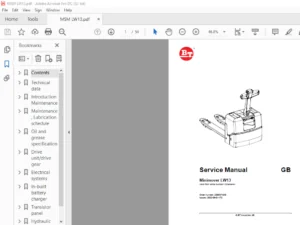
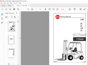
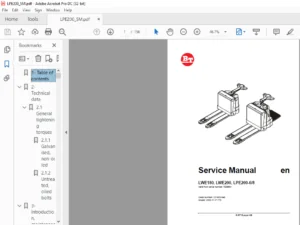
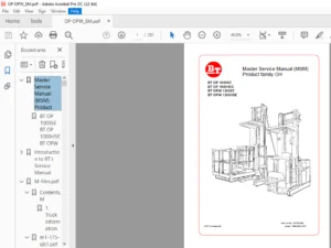
IMAGES PREVIEW OF THE MANUAL:
TABLE OF CONTENTS:
BT Prime-Mover CSX10/20/30/40 Master Service Manual – PDF DOWNLOAD
Front Cover..................................................................................   0
Table of Contents............................................................................   3
Warning Symbols..............................................................................   5
	1. Warning Levels........................................................................   5
Prohibitory Symbols..........................................................................   6
	1.1 Ordinance Symbols....................................................................   6
Introduction, Service Manual.................................................................   7
Contents, Section M..........................................................................   9
	General Product Information..............................................................  11
		1. Presentation of the Walkie Trucks CSX20/30/40, WSX30/40, and WRX30................  11
			1.1 Intended Application of the Trucks...........................................  11
			1.2 Forbidden Application of the Truck...........................................  12
			1.3 Truck Data...................................................................  12
			1.4 CSX Dimensions...............................................................  13
			1.5 WSX Dimensions...............................................................  14
			1.6 WRX Dimensions...............................................................  15
			1.7 Data Plate...................................................................  16
		2. Main Components...................................................................  18
		Inch (SAE) and Metric Fasteners......................................................  21
		Introduction.........................................................................  22
			Nomenclature, Threads............................................................  22
			Strength Identification..........................................................  23
				Table #1 Bolts and Screws....................................................  24
				Table #2 Studs and Nuts......................................................  25
				Table #3 Torque Nuts.........................................................  26
				Table #4 Torque Nuts with Nylon Insert.......................................  27
			Table #5 Conversion Table for Metric and English Units...........................  28
			Table #6.........................................................................  30
	Technical Service Data...................................................................  31
	Ordering Spare Parts.....................................................................  35
Contents, Section P..........................................................................  37
	Introduction, Maintenance................................................................  39
		1. Safe Jacking Procedure............................................................  39
	Service Schedule.........................................................................  41
		1. Preventive Maintenance Schedule...................................................  41
		2. Planned Maintenance Procedures....................................................  45
			Services to be Performed Daily or at Each 8 Hour Operating Shift.................  45
				Battery......................................................................  45
				Hydraulic System.............................................................  45
				Frame/Sheet Metal............................................................  45
				Wheels/Tires.................................................................  46
				Functions/Operations.........................................................  46
			Services to be Performed Monthly or Every 250 Operating Hours....................  46
				Inspection...................................................................  46
				Transmission.................................................................  46
				Brakes.......................................................................  46
				Battery......................................................................  47
				Electrical Connections.......................................................  47
				Line Contactor Tips (NOT Sealed).............................................  47
				Motor Brushes................................................................  47
				Drive Motor..................................................................  48
				Hydraulic Reservoir..........................................................  48
				Frame Lube...................................................................  48
				Pivot Points.................................................................  48
			Services to be Performed Annually or Every 1000 Operating Hours..................  48
				Inspection...................................................................  49
				Transmission.................................................................  49
				Battery......................................................................  49
				Hydraulic System.............................................................  50
				Brakes.......................................................................  50
	Lubrication Chart........................................................................  51
	Oil and Grease Specifications............................................................  53
		1. Approved Oils and Grease..........................................................  53
Contents, Section S..........................................................................  55
	Chassis, CSX.............................................................................  57
		1. General...........................................................................  57
		2. Main Components...................................................................  58
	Chassis, WRX and WSX.....................................................................  59
		1. General...........................................................................  59
		2. Support Arms......................................................................  60
	Drive Motor..............................................................................  61
		1. General Information...............................................................  61
		2. Operating Conditions..............................................................  61
		3. Troubleshooting...................................................................  61
		Drive Motor 200 AMP..................................................................  69
			1. Component Repair..............................................................  70
			2. Inspection and Troubleshooting................................................  71
				2.1 Drive End Head...........................................................  71
				2.2 Commutator End Head......................................................  71
				2.3 Bearings.................................................................  71
				2.4 Brush and Commutator.....................................................  72
				2.5 Armature.................................................................  72
				2.6 Frame and Field Assembly.................................................  73
				2.7 Assembly.................................................................  75
			3. When Changing Brushes.........................................................  76
		Drive Motor 300 AMP..................................................................  77
			4. Component Repair..............................................................  78
			5. Inspection and Troubleshooting................................................  81
				5.1 Drive End Head...........................................................  81
				5.2 Commutator End Head......................................................  81
				5.3 Bearings.................................................................  81
				5.4 Brush and Commutator.....................................................  82
				5.5 Armature.................................................................  82
				5.6 Frame and Field Assembly.................................................  83
				5.7 Assembly.................................................................  85
			6. When Changing Brushes.........................................................  86
	Transmission.............................................................................  87
		1. System Description................................................................  87
		2. Troubleshooting...................................................................  88
		3. Axle Seal Removal and Installation................................................  89
			3.1 Removal......................................................................  89
			3.2 Installation.................................................................  89
		4. Transmission Removal/Installation.................................................  90
			4.1 Removal......................................................................  90
			4.2 Installation.................................................................  91
		5. Transmission Assembly.............................................................  93
			5.1 Disassembly..................................................................  94
			5.2 Assembly.....................................................................  94
	Parking Brake System.....................................................................  97
		1. Brake Theory of Operation.........................................................  99
		2. Brake Adjustment.................................................................. 100
		3. Brake Shoe Removal/Installation................................................... 101
	Wheels................................................................................... 103
		1. Stabilizing Caster................................................................ 103
			1.1 Maintenance and Adjustments.................................................. 104
			1.2 Caster Adjustment............................................................ 104
			1.3 Troubleshooting.............................................................. 105
			1.4 Stabilizing Caster........................................................... 105
		2. Drive Wheel....................................................................... 107
			2.1 Removal...................................................................... 107
			2.2 Installation................................................................. 108
	Load Wheels, CSX......................................................................... 109
	Load Wheels, WRX/WSX..................................................................... 111
	Steering................................................................................. 113
		1. Control Handle Head............................................................... 113
			1.1 Removal...................................................................... 113
			1.2 Installation................................................................. 114
		2. Control Handle Stem............................................................... 114
			2.1 Removal...................................................................... 114
			2.2 Installation................................................................. 114
	Electrical System........................................................................ 117
		1. Electrical Panel Components....................................................... 117
		2. List of Symbols................................................................... 118
			2.1 Circuit Diagram 1(5)......................................................... 120
			2.2 Circuit Diagram 2(5)......................................................... 121
			2.3 Circuit Diagram 3(5)......................................................... 122
			2.4 Circuit Diagram 4(5)......................................................... 123
			2.5 Circuit Diagram 5(5)......................................................... 124
		3. Description of Function........................................................... 125
			3.1 General...................................................................... 125
			3.2 Adjustable Settings.......................................................... 125
			3.3 References................................................................... 125
			3.4 Key Switch S17 in the ON Position............................................ 125
			3.5 The Operating Arm in Drive Position, S10, Brake Switch Closed................ 126
			3.6 Driving, Fork Direction...................................................... 126
			3.7 Driving, Steer Wheel Direction............................................... 126
			3.8 Reversing/Motor Brake Fork Direction to Steer Wheel Direction................ 126
			3.9 Reversing/Motor Brake Steer Wheel Direction to Fork Direction................ 126
			3.10 Reverser Switch............................................................. 127
			3.11 Lifting the Forks........................................................... 127
			3.12 Lowering the Forks.......................................................... 127
			3.13 Horn........................................................................ 127
		4. Options........................................................................... 128
			4.1 Lifting the Forks (Manual Valve)............................................. 128
			4.2 Tilting the Forks............................................................ 128
			4.3 Sideshifting the Forks....................................................... 128
			4.4 Extend/Retract the Forks..................................................... 128
	Contactor, 300 AMP....................................................................... 131
		1. Maintenance....................................................................... 131
			1.1 Removal/Replacement of Contact Tips.......................................... 132
	Contactor, "EE".......................................................................... 135
		2. Maintenance....................................................................... 136
			2.1 Removal/Replacement of Contact Tips.......................................... 136
	Battery Controller/Hourmeter............................................................. 139
		1. General........................................................................... 139
		2. Electrical........................................................................ 139
			2.1 Voltage...................................................................... 139
		3. Battery Controller (BC)........................................................... 140
			3.1 General...................................................................... 140
			3.2 Reset........................................................................ 142
			3.3 Key Switch................................................................... 142
			3.4 Hourmeter.................................................................... 142
		4. Troubleshooting................................................................... 143
			4.1 Battery Discharge Indicator (BDI)............................................ 143
			4.2 Hourmeter.................................................................... 145
	Transistor Controller.................................................................... 147
		1. Motor Circuit..................................................................... 147
		2. Control Circuit................................................................... 148
		3. Technical Specification........................................................... 150
		4. Adjustment of Controller.......................................................... 152
			4.1 Connection of Handset........................................................ 152
		5. Maintenance....................................................................... 153
			5.1 Safety....................................................................... 153
			5.2 Cleaning..................................................................... 153
		6. Diagnostics and Troubleshooting................................................... 154
			6.1 Handset Diagnostics.......................................................... 154
			6.2 Troubleshooting.............................................................. 154
			6.3 Troubleshooting Chart Using the Handset...................................... 157
	Electrical System Troubleshooting Chart Index............................................ 159
	Electrical System Troubleshooting Charts................................................. 161
	Handset Operation........................................................................ 179
		1. Operating Modes................................................................... 180
		2. Peace of Mind Programming......................................................... 184
		3. Handset Self Test................................................................. 185
	Pump Motor............................................................................... 187
		1. Component Repair.................................................................. 188
		2. Inspection and Troubleshooting.................................................... 190
			2.1 Drive End Head............................................................... 190
			2.2 Commutator End Head.......................................................... 190
			2.3 Bearings..................................................................... 190
			2.4 Brush and Commutator......................................................... 191
			2.5 Armature..................................................................... 191
			2.6 Frame and Field Assembly..................................................... 192
			2.7 Assembly..................................................................... 194
		3. When Changing Brushes............................................................. 195
	Hydraulic System......................................................................... 197
		1. General........................................................................... 197
		2. Description of Function........................................................... 197
			2.1 Hydraulic Schematic.......................................................... 197
			CSX Hydraulic Schematic.......................................................... 198
			WRX Hydraulic Schematic.......................................................... 199
			WSX Hydraulic Schematic.......................................................... 200
			2.2 Main Components.............................................................. 201
			2.3 Description.................................................................. 201
		3. Maintenance....................................................................... 202
			3.1 Maintenance and Adjustments.................................................. 202
			3.2 Troubleshooting.............................................................. 203
				Relief Valve................................................................. 205
				Figure 6110.................................................................. 206
				Solenoid Operated Valve...................................................... 207
				Pump and Motor............................................................... 207
				Reservoir and Pump........................................................... 208
	Manual Spool Valve....................................................................... 211
		Figure 0640.......................................................................... 211
		Figure 6160.......................................................................... 212
		Removal.............................................................................. 213
		Disassembly and Inspection........................................................... 214
		Assembly............................................................................. 215
	Mast, 2 Stage............................................................................ 217
		1. Shimming.......................................................................... 219
			1.1 Shimming the Carriage........................................................ 219
			1.2 Shimming the Rails........................................................... 220
		2. Two Stage Mast.................................................................... 222
			2.1 Removal...................................................................... 222
			2.2 Installation................................................................. 224
			2.3 Disassembly.................................................................. 225
			2.4 Assembly..................................................................... 226
	Mast, 3 Stage............................................................................ 229
		1. Shimming.......................................................................... 230
			1.1 Shimming the Carriage........................................................ 230
			1.2 Shimming the Rails........................................................... 231
		2. Three Stage Mast.................................................................. 234
			2.1 Removal...................................................................... 234
			2.2 Installation................................................................. 235
			2.3 Disassembly.................................................................. 236
			2.4 Assembly..................................................................... 237
	Reach.................................................................................... 241
		1. Maintenance....................................................................... 241
		2. Reach Repair...................................................................... 242
			2.1 Disassembly.................................................................. 242
			2.2 Assembly..................................................................... 243
	Lift Cylinder, 2 Stage................................................................... 247
		1. Two Stage Full Freelift Mast Freelift Cylinder Repair............................. 248
			1.2 Disassembly.................................................................. 248
			1.3 Assembly..................................................................... 248
			1.4 Installation................................................................. 249
		2. Two Stage Full Freelift Mast Staging Cylinder Repair.............................. 250
			2.1 Removal...................................................................... 250
			2.2 Disassembly.................................................................. 250
			2.3 Assembly..................................................................... 250
			2.4 Installation................................................................. 251
		3. Two Stage Mast Lift Cylinder Repair............................................... 252
			3.1 Removal...................................................................... 252
			3.2 Disassembly.................................................................. 252
			3.3 Assembly..................................................................... 252
			3.4 Installation................................................................. 253
	Lift Cylinder, 3 Stage................................................................... 255
		1. Freelift Cylinder Repair.......................................................... 256
			1.1 Removal...................................................................... 256
			1.2 Disassembly.................................................................. 256
			1.3 Assembly..................................................................... 256
			1.4 Installation................................................................. 257
		2. Staging Cylinder Repair........................................................... 258
			2.1 Removal...................................................................... 258
			2.2 Disassembly.................................................................. 258
			2.3 Assembly..................................................................... 258
			2.4 Installation................................................................. 259
	Tilt Cylinder, CSX....................................................................... 261
		1. Removal........................................................................... 262
		2. Disassembly....................................................................... 262
		3. Inspection........................................................................ 263
		4. Assembly.......................................................................... 264
		5. Installation...................................................................... 264
	Tilt Cylinder, WRX....................................................................... 267
		1. Removal........................................................................... 268
		2. Disassembly....................................................................... 268
		3. Inspection........................................................................ 269
		4. Assembly.......................................................................... 269
		5. Installation...................................................................... 270
	Reach Cylinder, WRX...................................................................... 273
		1. Removal........................................................................... 274
		2. Disassembly....................................................................... 274
		3. Inspection........................................................................ 275
		4. Assembly.......................................................................... 275
		5. Installation...................................................................... 276
Back Cover................................................................................... 278
Front Cover.................................................................................. 279
BT Standard Codes............................................................................ 281
Table of Contents............................................................................ 283
Warning Symbols.............................................................................. 287
	H 1. Warning Levels...................................................................... 287
Prohibitory Symbols.......................................................................... 288
	1. Ordinance Symbols..................................................................... 288
Introduction, Service Manual................................................................. 289
Contents, Section M.......................................................................... 291
	1. Machine Information................................................................... 291
General Product Information.................................................................. 293
	1. Presentation of the Walkie Trucks..................................................... 293
		H Heading3 First - 1.1. Intended Application of the Trucks........................... 293
		H Heading3 - 1.2. Forbidden Application of the Truck................................. 294
		H Heading3 - 1.3. Truck Data......................................................... 294
		H Heading3 - 1.4. CSX Dimensions..................................................... 295
		H Heading3 - 1.5. WSX Dimensions..................................................... 296
		H Heading3 - 1.6. WRX Dimensions..................................................... 297
		H Heading3 - 1.7. Data Plate......................................................... 298
	2. Main Components....................................................................... 299
Inch (SAE) and Metric Fasteners.............................................................. 303
	1. Introduction.......................................................................... 303
	2. Nomenclature, Threads................................................................. 304
	3. Strength Identification............................................................... 305
	4. Conversion of Metric and English Units................................................ 311
Technical Service Data....................................................................... 313
Ordering Spare Parts......................................................................... 317
Contents, Section P.......................................................................... 319
	1. Planned Maintenance................................................................... 319
Introduction, Maintenance.................................................................... 321
	1. Safe Jacking Procedure................................................................ 321
Service Schedule............................................................................. 323
	1. Planned Maintenance Schedule.......................................................... 323
	2. Planned Maintenance Procedures........................................................ 329
		H Heading3 First - 2.1. Services to be performed daily............................... 329
			H Heading4 First - 2.1.1. Battery Discharge Indicator with slow down............. 329
			H Heading4 - 2.1.2. Hydraulic System............................................. 329
			H Heading4 - 2.1.3. Frame/Sheet Metal............................................ 330
			H Heading4 - 2.1.4. Wheels/Tires................................................. 330
			H Heading4 - 2.1.5. Functions/Operations......................................... 330
		2.2. Services to be performed monthly................................................ 331
			2.2.1. Inspection................................................................ 331
			2.2.2. Transmission.............................................................. 331
			2.2.3. Brakes.................................................................... 331
			2.2.4. Battery................................................................... 331
			2.2.5. Electrical Connections.................................................... 331
			2.2.6. Contactor Tips (NOT Sealed)............................................... 332
			2.2.7. Motor Brushes............................................................. 332
			2.2.8. Drive Motor............................................................... 332
			2.2.9. Hydraulic Reservoir....................................................... 332
			2.2.10. Frame Lube (“Lubrication Chart” on page 57).............................. 332
			2.2.11. Pivot Points............................................................. 333
		2.3. Services to be performed annually............................................... 334
			2.3.1. Inspection................................................................ 334
			2.3.2. Transmission.............................................................. 334
			2.3.3. Battery................................................................... 334
			2.3.4. Hydraulic System.......................................................... 334
			2.3.5. Brakes.................................................................... 335
Lubrication Chart............................................................................ 337
Oil and Grease Specifications................................................................ 339
	1. Approved Oils and Grease.............................................................. 339
Contents, Section S.......................................................................... 341
	1. Service Instructions.................................................................. 341
Chassis, CSX................................................................................. 343
	1. General............................................................................... 343
	2. Main Components....................................................................... 344
Chassis, WRX and WSX......................................................................... 345
	1. General............................................................................... 345
	2. Support Arms.......................................................................... 346
Drive Motor.................................................................................. 347
	1. General Information................................................................... 347
	2. Operating Conditions.................................................................. 347
	3. Troubleshooting....................................................................... 347
Drive Motor 200 AMP.......................................................................... 353
	1. Component Repair...................................................................... 354
		1.1. Disassembly..................................................................... 354
	2. Inspection and Troubleshooting........................................................ 356
		2.1. Drive End Head.................................................................. 356
		2.2. Commutator End Head............................................................. 356
		2.3. Bearings........................................................................ 356
		2.4. Brush and Commutator............................................................ 357
		2.5. Armature........................................................................ 357
		2.6. Frame and Field Assembly........................................................ 358
			2.6.1. Testing................................................................... 358
			2.6.2. Frame and Field Service Notes............................................. 359
		2.7. Assembly........................................................................ 360
			2.7.1. Field Coil Installation................................................... 360
			2.7.2. Bearing Installation...................................................... 360
			2.7.3. After Assembly............................................................ 361
	3. When Changing Brushes................................................................. 361
Drive Motor 300 AMP.......................................................................... 363
	1. Component Repair...................................................................... 364
	2. Inspection and Troubleshooting........................................................ 367
		2.1. Drive End Head.................................................................. 367
		2.2. Commutator End Head............................................................. 367
		2.3. Bearings........................................................................ 367
		2.4. Brush and Commutator............................................................ 368
		2.5. Armature........................................................................ 368
		2.6. Frame and Field Assembly........................................................ 369
			2.6.1. Testing................................................................... 369
			2.6.2. Frame and Field Service Notes............................................. 370
		2.7. Assembly........................................................................ 371
			2.7.1. Field Coil Installation................................................... 371
			2.7.2. Bearing Installation...................................................... 371
			2.7.3. After Assembly............................................................ 372
	3. When changing brushes................................................................. 372
Transmission................................................................................. 373
	1. System description.................................................................... 373
	2. Troubleshooting....................................................................... 373
	3. Removal............................................................................... 375
	4. Installation.......................................................................... 377
Transmission Axle Seal....................................................................... 379
	1. General Information................................................................... 379
		1.1. Removal......................................................................... 379
		1.2. Installation.................................................................... 379
Transmission Disassembly / Assembly.......................................................... 381
	1. Disassembly........................................................................... 382
	2. Assembly.............................................................................. 382
Parking Brake System......................................................................... 385
	1. Brake Theory of Operation............................................................. 387
	2. Brake Adjustment...................................................................... 388
	3. Brake Shoe Removal / Installation..................................................... 389
Drive Wheel.................................................................................. 391
	3.1. Removal............................................................................. 391
	3.2. Installation........................................................................ 392
Load Wheels, CSX............................................................................. 393
	1. Removeal and Installation............................................................. 393
Load Wheels, WRX/WSX......................................................................... 395
	1. Removal and Installation.............................................................. 395
Wheels....................................................................................... 397
	1. Stabilizing Caster.................................................................... 397
		1.1. Maintenance and Adjustments..................................................... 398
		1.2. Caster Adjustment............................................................... 398
		1.3. Troubleshooting................................................................. 399
		1.4. Stabilizing Caster.............................................................. 399
			1.4.1. Caster Replacement........................................................ 399
Stabilizing Caster........................................................................... 401
	1. Stabilizing Caster.................................................................... 401
		1.1. Disassembly..................................................................... 402
		1.2. Inspection...................................................................... 403
		1.3. Assembly........................................................................ 404
Steering Arm / Handle........................................................................ 405
	1. Control Handle Stem................................................................... 406
		1.1. Removal......................................................................... 406
		1.2. Inspection...................................................................... 406
		1.3. Installation.................................................................... 407
Steering Handle Head......................................................................... 409
	1. Control Handle Head................................................................... 411
		1.1. Removal......................................................................... 411
		1.2. Installation.................................................................... 411
	2. Direction Control Switches............................................................ 412
	3. Horn, Raise, and Lower Switches....................................................... 413
	4. Potentiometer......................................................................... 415
Electrical System............................................................................ 417
	1. Electrical Panel Components........................................................... 417
	2. List of Symbols....................................................................... 418
		2.1. Circuit Diagram 1(5)............................................................ 420
		2.2. Circuit Diagram 2(5)............................................................ 421
		2.3. Circuit Diagram 3(5)............................................................ 422
		2.4. Circuit Diagram 4(5)............................................................ 423
		2.5. Circuit Diagram 5(5)............................................................ 424
	3. Description of Function............................................................... 425
		3.1. General......................................................................... 425
		3.2. Adjustable Settings:............................................................ 425
		3.3. References:..................................................................... 425
		3.4. Key Switch S17 in the ON Position............................................... 425
		3.5. The Operating Arm in Drive Position, S10, Brake Switch Closed................... 426
		3.6. Driving, Fork Direction......................................................... 426
		3.7. Driving, Steer Wheel Direction.................................................. 426
		3.8. Reversing/Motor Brake Fork Direction to Steer Wheel Direction................... 426
		3.9. Reversing/Motor Brake Steer Wheel Direction to Fork Direction................... 426
		3.10. Reverser switch................................................................ 427
		3.11. Lifting the Forks.............................................................. 427
		3.12. Lowering the Forks............................................................. 427
		3.13. Horn........................................................................... 427
	4. Options............................................................................... 428
		4.1. Lifting the Forks (Manual Valve)................................................ 428
		4.2. Tilting the Forks............................................................... 428
		4.3. Sideshifting the Forks.......................................................... 428
		4.4. Extend/Retract the Forks........................................................ 428
300/400 Amp Contactor........................................................................ 431
	1. Maintenance........................................................................... 432
		1.1. Removal/Replacement of Contact Tips............................................. 432
“EE” Contactor............................................................................... 435
	1. Maintenance........................................................................... 436
		1.1. Removal/Replacement of Contact Tips............................................. 436
Battery Controller / Hourmeter / Lift Interrupt.............................................. 439
	1. General Information................................................................... 439
	2. Electrical............................................................................ 439
		2.1. Voltage......................................................................... 439
			2.1.1. The Contact Voltage and Current Ratings for Switching Resistive Loads..... 440
			2.1.2. Memory Retention.......................................................... 440
	3. Battery Controller (BC)............................................................... 440
		3.1. General Information............................................................. 440
			3.1.1. Discharge Adjustment...................................................... 440
		3.2. Reset........................................................................... 442
		3.3. Key Switch...................................................................... 442
		3.4. Hourmeter....................................................................... 443
	4. Troubleshooting....................................................................... 443
		4.1. Battery Discharge Indicator (BDI)............................................... 443
			4.1.1. No Reset.................................................................. 443
			4.1.2. Reset After Break in Power................................................ 443
			4.1.3. No Discharge, Gauge Does Not Run Down..................................... 444
			4.1.4. No Lockout................................................................ 444
			4.1.5. No Lift................................................................... 444
			4.1.6. Early Lockout............................................................. 445
			4.1.7. LEDs Do Not Light......................................................... 445
		4.2. Hourmeter....................................................................... 445
			4.2.1. No Display................................................................ 445
			4.2.2. Hourmeter Glass Icon Does Not Flash....................................... 445
			4.2.3. Hourmeter Glass Icon Always Flashes....................................... 446
Transistor Controller........................................................................ 447
	1. Motor Circuit......................................................................... 447
	2. Control Circuit....................................................................... 448
	3. Technical Specification............................................................... 450
	4. Adjustment of Controller.............................................................. 452
		4.1. Connection of Handset........................................................... 452
	5. Maintenance........................................................................... 453
		5.1. Safety.......................................................................... 453
		5.2. Cleaning........................................................................ 453
	6. Diagnostics and Troubleshooting....................................................... 454
		6.1. Handset Diagnostics............................................................. 454
		6.2. Troubleshooting................................................................. 454
			6.2.1. Procedure Troubleshooting Instructions.................................... 456
		6.3. Troubleshooting Chart Using the Handset......................................... 457
Electrical System Troubleshooting Chart Index................................................ 459
Electrical System Troubleshooting Charts..................................................... 461
Handset Operation............................................................................ 479
	1. Operating Modes:...................................................................... 480
	2. Revert to Previous Settings........................................................... 484
	3. Handset Self Test..................................................................... 485
	4. LED Diagnostics....................................................................... 486
Pump Motor................................................................................... 487
	1. Component Repair...................................................................... 488
		1.1. Disassembly..................................................................... 488
	2. Inspection and Troubleshooting........................................................ 490
		2.1. Drive End Head.................................................................. 490
		2.2. Commutator End Head............................................................. 490
		2.3. Bearings........................................................................ 490
		2.4. Brush and Commutator............................................................ 491
		2.5. Armature........................................................................ 491
		2.6. Frame and Field Assembly........................................................ 492
			2.6.1. Testing................................................................... 492
			2.6.2. Frame and Field Service Notes............................................. 493
		2.7. Assembly........................................................................ 494
			2.7.1. Field Coil Installation................................................... 494
			2.7.2. Bearing Installation...................................................... 494
			2.7.3. After Assembly............................................................ 495
	3. When changing brushes................................................................. 495
Hydraulic System............................................................................. 497
	1. General............................................................................... 497
	2. Description of Function............................................................... 497
		2.1. Hydraulic Schematic............................................................. 497
		2.2. CSX Hydraulic Schematic......................................................... 498
		2.3. WRX Hydraulic Schematic......................................................... 499
		2.4. WSX Hydraulic Schematic......................................................... 500
	3. Main Components....................................................................... 501
		3.1. Description..................................................................... 501
			3.1.1. Lift (Solenoid valve)..................................................... 501
			3.1.2. Lift (Mechanical Valve)................................................... 501
			3.1.3. Lower (Solenoid Valve).................................................... 501
			3.1.4. Lower (Mechanical Valve).................................................. 502
			3.1.5. Relief Pressure........................................................... 502
			3.1.6. Compensating Cylinder..................................................... 502
	4. Maintenance........................................................................... 502
	5. Adjustments........................................................................... 502
	6. Troubleshooting....................................................................... 503
		6.1. Primary Malfunctions............................................................ 503
			6.1.1. Failure to raise the load................................................. 504
			6.1.2. Failure to raise the load................................................. 504
			6.1.3. Failure to raise the load................................................. 504
	7. Removal............................................................................... 505
	8. Installation.......................................................................... 507
Lift Pump Assembly........................................................................... 509
	1. Disassembly........................................................................... 511
	2. Inspection............................................................................ 512
	3. Assembly.............................................................................. 513
Manual Spool Valve........................................................................... 515
	1. Removal............................................................................... 517
	2. Disassembly and Inspection............................................................ 518
	3. Assembly.............................................................................. 519
Mast, 2 Stage................................................................................ 521
	1. Shimming Mast on Truck................................................................ 523
		1.1. Shimming the Carriage........................................................... 523
		1.2. Shimming the Rails.............................................................. 524
	2. Two Stage Mast........................................................................ 526
		2.1. Removal......................................................................... 526
		2.2. Installation.................................................................... 528
		2.3. Disassembly..................................................................... 529
		2.4. Assembly........................................................................ 530
Mast, 3 Stage................................................................................ 533
	1. Shimming Mast on Truck................................................................ 534
		1.1. Shimming the Carriage........................................................... 534
		1.2. Shimming the Rails.............................................................. 535
	2. Three Stage Mast...................................................................... 539
		2.1. Removal......................................................................... 539
		2.2. Installation.................................................................... 540
		2.3. Disassembly..................................................................... 541
		2.4. Assembly........................................................................ 543
Sideshifter.................................................................................. 547
	1. Mounting Instructions................................................................. 549
		1.1. Installation.................................................................... 549
	2. Operation and Maintenance............................................................. 550
		2.1. Lower Slides.................................................................... 551
		2.2. Upper Slides.................................................................... 551
		2.3. Cylinder........................................................................ 551
Reach, Single................................................................................ 553
	1. Maintenance........................................................................... 553
	2. Reach Repair.......................................................................... 555
		2.1. Disassembly..................................................................... 555
			2.1.1. Front Frame Removal....................................................... 555
			2.1.2. Outer Arm Removal......................................................... 555
			2.1.3. Inner Arm Removal......................................................... 555
			2.1.4. Rear Frame Removal........................................................ 556
			2.1.5. Reach Cylinder Removal.................................................... 556
		2.2. Assembly........................................................................ 557
			2.2.1. Reach Cylinder Installation............................................... 557
			2.2.2. Rear Frame Installation................................................... 557
			2.2.3. Inner Arm Installation.................................................... 557
			2.2.4. Outer Arm Installation.................................................... 558
Lift Cylinder, 2 Stage....................................................................... 559
	1. Two Stage Full Freelift Mast Freelift Cylinder Repair................................. 560
		1.1. Removal......................................................................... 560
		1.2. Disassembly..................................................................... 561
		1.3. Assembly........................................................................ 561
		1.4. Installation.................................................................... 561
	2. Two Stage Full Freelift Mast Staging Cylinder Repair.................................. 562
		2.1. Removal......................................................................... 562
		2.2. Disassembly..................................................................... 562
		2.3. Assembly........................................................................ 563
		2.4. Installation.................................................................... 563
	3. Two Stage Mast Lift Cylinder Repair................................................... 564
		3.1. Removal......................................................................... 564
		3.2. Disassembly..................................................................... 564
		3.3. Assembly........................................................................ 565
		3.4. Installation.................................................................... 565
Freelift Cylinder, 3 Stage................................................................... 567
	1. Freelift Cylinder Repair.............................................................. 568
		1.1. Removal......................................................................... 568
		1.2. Disassembly..................................................................... 569
		1.3. Assembly........................................................................ 569
		1.4. Installation.................................................................... 569
Tilt Cylinder, CSX........................................................................... 571
	1. Removal............................................................................... 572
	2. Disassembly........................................................................... 573
	3. Inspection............................................................................ 574
	4. Assembly.............................................................................. 575
	5. Installation.......................................................................... 576
Tilt Cylinder, WRX........................................................................... 577
	1. Removal............................................................................... 578
	2. Disassembly........................................................................... 579
	3. Inspection............................................................................ 580
	4. Assembly.............................................................................. 581
	5. Installation.......................................................................... 582
Reach Cylinder............................................................................... 583
	1. Removal............................................................................... 584
	2. Disassembly........................................................................... 585
	3. Inspection............................................................................ 586
	4. Assembly.............................................................................. 587
	5. Installation.......................................................................... 588
Back Cover................................................................................... 590
Front Cover.................................................................................. 591
Standard Codes............................................................................... 593
Index........................................................................................ 595
Warning Symbols.............................................................................. 605
	1. Warning Levels........................................................................ 605
Prohibitory Symbols.......................................................................... 606
	1. Ordinance Symbols..................................................................... 606
Safety....................................................................................... 607
	1. General Safety........................................................................ 607
Battery Safety............................................................................... 611
Static Safety................................................................................ 616
Welding Safety............................................................................... 617
Introduction, Service Manual................................................................. 619
Contents, Section M.......................................................................... 621
	1. Machine Information................................................................... 621
General Product Information.................................................................. 623
	1. Presentation of Walkie Trucks......................................................... 623
		1.1. Truck Side Views................................................................ 624
		1.1. Intended Truck Application...................................................... 624
		1.2. Prohibited Truck Application.................................................... 624
		1.3. Truck Data...................................................................... 625
		1.4. CSX10 Dimensions................................................................ 626
		1.5. CSX20 Dimensions................................................................ 627
		1.6. CSX30 Dimensions................................................................ 628
		1.7. CSX40 Dimensions................................................................ 629
		1.8. WSX22 Dimensions................................................................ 630
		1.9. WSX30 Dimensions................................................................ 631
		1.10. WSX40 Dimensions............................................................... 632
		1.11. WRX30 Dimensions............................................................... 633
		1.12. Data Plate..................................................................... 634
	2. Main Components....................................................................... 636
Inch (SAE) and Metric Fasteners.............................................................. 639
	1. Introduction.......................................................................... 639
	2. Nomenclature, Threads................................................................. 640
	3. Strength Identification............................................................... 641
	4. Conversion of Metric and English Units................................................ 648
Technical Service Data....................................................................... 651
Ordering Spare Parts......................................................................... 655
Contents, Section P.......................................................................... 657
	1. Planned Maintenance................................................................... 657
Introduction, Maintenance.................................................................... 659
	1. Jacking Truck Off The Floor........................................................... 660
		1.1. Elevate Rear of Truck........................................................... 660
		1.1. Elevate Either Side of Truck.................................................... 660
	2. Lubricants............................................................................ 661
		2.1. Standard........................................................................ 661
		2.2. Corrosion....................................................................... 661
		2.3. Cold Storage.................................................................... 662
Service Schedule............................................................................. 665
	1. Planned Maintenance Schedule.......................................................... 665
	2. Planned Maintenance Procedures........................................................ 670
		2.1. Services Performed Daily or Every 8 Operating Hours............................. 670
			2.1.1. Battery Discharge Indicator with slow down................................ 670
			2.1.2. Hydraulic System.......................................................... 670
			2.1.3. Frame/Sheet Metal......................................................... 671
			2.1.4. Wheels/Tires.............................................................. 671
			2.1.5. Functions/Operations...................................................... 671
		2.2. Services Performed Monthly or Every 120 Operating Hours......................... 671
			2.2.1. Inspection................................................................ 671
			2.2.2. Transmission.............................................................. 671
			2.2.3. Brakes.................................................................... 672
			2.2.4. Battery................................................................... 672
			2.2.5. Electrical Connections.................................................... 672
			2.2.6. Contactor Tips (NOT Sealed)............................................... 672
			2.2.7. Motor Brushes............................................................. 672
			2.2.8. Drive Motor............................................................... 673
			2.2.9. Hydraulic Reservoir....................................................... 673
			2.2.10. Frame Lube............................................................... 673
			2.2.11. Pivot Points............................................................. 673
		2.3. Services Performed Every 480 or 960 Operating Hours............................. 674
			2.3.1. Drive Motor............................................................... 674
		2.4. Services Performed Annually or Every 1400 Operating Hours....................... 675
			2.4.1. Inspection................................................................ 675
			2.4.2. Transmission.............................................................. 675
			2.4.3. Battery................................................................... 675
			2.4.4. Hydraulic System.......................................................... 676
			2.4.5. Brakes.................................................................... 676
			2.4.6. Lift and Carriage Chains.................................................. 676
Lubrication Chart............................................................................ 677
Oil and Grease Specifications................................................................ 678
	1. Approved Oils and Grease.............................................................. 678
	2. CSX Grease & Mast Adjustment Points Location.......................................... 679
	3. WSX Grease & Mast Adjustment Points Location.......................................... 680
	4. WRX Grease & Mast Adjustment Points Location.......................................... 681
Contents, Section S.......................................................................... 683
	1. Service Instructions.................................................................. 683
Frame/Chassis................................................................................ 685
	1. General............................................................................... 687
	2. Main Components....................................................................... 687
Inspection Covers............................................................................ 689
Battery Roller (Optional).................................................................... 697
	1. Battery Cover, Optional (WSX22 “EE” Trucks Only)...................................... 699
		1.1. Inspection...................................................................... 699
		1.2. Removal......................................................................... 699
		1.3. Installation.................................................................... 700
	2. Battery Rollers....................................................................... 700
		2.1. Inspection...................................................................... 700
		2.2. Replacement..................................................................... 700
Driver Controls, One Spool................................................................... 701
	1. Removal............................................................................... 703
	2. Installation.......................................................................... 704
Driver Controls, Two Spool................................................................... 705
	1. Removal............................................................................... 708
	2. Installation.......................................................................... 709
Decals....................................................................................... 711
	1. Decal with Protective Sheet........................................................... 711
	2. Decal without Protective Sheet........................................................ 711
Motor Maintenance Schedule/Troubleshooting................................................... 715
	1. General Information................................................................... 715
	2. Operating Conditions.................................................................. 715
	3. Troubleshooting....................................................................... 716
Motor Repair................................................................................. 723
	1. Pump Motor............................................................................ 723
		1.1. Pump Motor Removal.............................................................. 724
		1.2. Pump Motor Installation......................................................... 724
	2. Drive Motor........................................................................... 725
		2.1. Brush Replacement............................................................... 731
		2.2. Drive Motor Removal............................................................. 731
		2.3. Drive Motor Installation........................................................ 732
	3. Component Repair...................................................................... 734
		3.1. Disassembly..................................................................... 734
	4. Inspection............................................................................ 736
		4.1. Drive End head.................................................................. 736
		4.2. Commutator End Head............................................................. 736
		4.3. Bearings........................................................................ 736
		4.4. Brush and Commutator............................................................ 737
		4.5. Armature........................................................................ 739
		4.6. Frame and Field Assembly........................................................ 740
			4.6.1. Testing................................................................... 740
		4.7. Assembly/Testing................................................................ 741
			4.7.1. Bearing Installation...................................................... 741
			4.7.2. Testing................................................................... 742
Transmission................................................................................. 743
	1. System Description.................................................................... 743
	2. Troubleshooting....................................................................... 743
		2.1. Kick Panel...................................................................... 744
	3. Transmission Repair................................................................... 745
		3.1. Removal......................................................................... 746
		3.2. Installation.................................................................... 747
	4. Transmission Assembly................................................................. 749
		4.1. Disassembly..................................................................... 750
		4.2. Assembly........................................................................ 750
	5. Axle Seal............................................................................. 752
		5.1. Removal......................................................................... 752
		5.2. Installation.................................................................... 752
Parking Brake System......................................................................... 755
	1. Brake Theory of Operation............................................................. 757
	2. Brake Adjustment...................................................................... 758
	3. Brake Shoe Removal / Installation..................................................... 759
Drive Wheel.................................................................................. 761
	1. Removal............................................................................... 761
	2. Installation.......................................................................... 762
	3. Tire Pressing Procedure............................................................... 763
Support/Swivel Wheel......................................................................... 765
	1. Maintenance and Adjustments........................................................... 768
		1.1. Caster Adjustment............................................................... 769
	2. Troubleshooting....................................................................... 770
		2.1. Stabilizing Caster.............................................................. 770
			2.1.1. Caster Replacement........................................................ 770
Load Wheels.................................................................................. 771
	1. Removal and Installation.............................................................. 774
Caster Assembly.............................................................................. 775
	1. Disassembly........................................................................... 776
	2. Inspection............................................................................ 777
	3. Assembly.............................................................................. 778
Steering Arm/Wheel, Tiler Arm (Serial # 25268000 - 27323000)................................. 779
	1. Removal............................................................................... 780
	2. Inspection............................................................................ 781
	3. Installation.......................................................................... 782
Steering Arm/Wheel, Tiler Arm (Serial # 27323001 - UP)....................................... 783
	1. Removal............................................................................... 784
	2. Inspection............................................................................ 785
	3. Installation.......................................................................... 786
Steering Arm/Wheel, Head..................................................................... 787
	1. Control Handle Head................................................................... 788
		1.1. Removal......................................................................... 788
		1.2. Installation.................................................................... 788
	2. Direction Control Switches............................................................ 789
	3. Raise, Lower, and Horn Switches....................................................... 791
	4. Potentiometer......................................................................... 794
		4.1. Removal......................................................................... 794
		4.2. Installation.................................................................... 795
	5. Reverser Assembly Replacement......................................................... 799
Electrical Functions......................................................................... 801
	1. General............................................................................... 801
		1.1. Adjustable Settings............................................................. 801
		1.2. References...................................................................... 801
		1.3. Key Switch S17 in ON Position................................................... 802
		1.4. Operating Arm in Drive Position, S10, Brake Switch Closed....................... 802
		1.5. Travel Request, Forks First..................................................... 802
		1.6. Travel Request, Forks Trailing.................................................. 802
		1.7. Reversing/Motor Brake Forks First to Forks Trailing Direction................... 803
		1.8. Reversing/Motor Brake Forks Trailing to Forks First Direction................... 803
		1.9. Reverser switch................................................................. 803
		1.10. Lifting Forks.................................................................. 803
		1.11. Lowering Forks................................................................. 804
		1.12. Horn........................................................................... 804
	2. Options............................................................................... 804
		2.1. Lifting Forks (Manual Valve).................................................... 804
		2.2. Tilting Forks................................................................... 804
		2.3. Side Shifting Forks............................................................. 804
		2.4. Extend/Retract Forks............................................................ 805
Electrical Symbols........................................................................... 807
Electrical Schematics........................................................................ 813
Battery...................................................................................... 819
	1. Removal............................................................................... 819
	2. Installation.......................................................................... 820
	3. Battery Maintenance................................................................... 821
		3.1. Battery Inspection and Care..................................................... 821
		3.2. Battery Exterior Cleaning....................................................... 822
		3.3. Charging........................................................................ 822
	4. Storage............................................................................... 823
	5. Battery History Record................................................................ 823
Battery Connector............................................................................ 825
	1. Location.............................................................................. 825
	2. Inspection............................................................................ 826
	3. Installation.......................................................................... 826
200 Amp System Line Contactor................................................................ 829
	1. Replacement........................................................................... 829
		1.1. Removal......................................................................... 829
		1.2. Installation.................................................................... 829
300 Amp System Line Contactor (CSX30/40 only)................................................ 831
	1. Maintenance........................................................................... 831
		1.1. Removal/Replacement of Contact Tips............................................. 832
200/300 Amp System “EE” Line Contactor....................................................... 833
	1. Maintenance........................................................................... 833
		1.1. Removal/Replacement of Contact Tips............................................. 834
Battery Controller/Hourmeter/Lift Interrupt.................................................. 837
	1. General Information................................................................... 837
	2. Electrical............................................................................ 838
		2.1. Voltage......................................................................... 838
	3. Battery Controller (BC)............................................................... 839
		3.1. General Information............................................................. 839
			3.1.1. Discharge Adjustment...................................................... 839
		3.2. Reset........................................................................... 841
		3.3. Key Switch...................................................................... 841
		3.4. Hourmeter....................................................................... 842
	4. Troubleshooting....................................................................... 842
		4.1. Battery Discharge Indicator (BDI)............................................... 842
			4.1.1. No Reset.................................................................. 842
			4.1.2. Reset After Break in Power................................................ 843
			4.1.3. No Discharge, Gauge Does Not Run Down..................................... 843
			4.1.4. No Lockout................................................................ 843
			4.1.5. No Lift................................................................... 844
			4.1.6. Early Lockout............................................................. 844
			4.1.7. LEDs Do Not Light......................................................... 844
		4.2. Hourmeter....................................................................... 845
			4.2.1. No Display................................................................ 845
			4.2.2. Hourmeter Glass Icon Does Not Flash....................................... 845
			4.2.3. Hourmeter Glass Icon Always Flashes....................................... 845
Start/Stop Switches.......................................................................... 847
	1. General............................................................................... 847
		1.1. Test/Inspection................................................................. 847
	2. Master Control On/Off Switch (S21).................................................... 849
		2.1. Inspection...................................................................... 849
		2.2. Removal......................................................................... 849
		2.3. Installation.................................................................... 849
Light Assemblies............................................................................. 851
	1. Warning Lights (Option)............................................................... 851
		1.1. Removal......................................................................... 853
		1.2. Installation.................................................................... 853
	2. Travel/Back-up Alarm (Option)......................................................... 854
		2.1. Removal......................................................................... 854
		2.2. Installation.................................................................... 854
Transistor Controller........................................................................ 855
	1. Basics Of Circuit Operation........................................................... 855
		1.1. Control Features................................................................ 857
	2. Maintenance........................................................................... 858
		2.1. Safety.......................................................................... 858
		2.2. Cleaning........................................................................ 858
	3. Motor Circuit......................................................................... 859
	4. Control Circuit....................................................................... 860
	5. Troubleshooting Guidelines............................................................ 861
		5.1. General......................................................................... 863
	6. Shorts to Frame Test.................................................................. 864
	7. Definitions........................................................................... 868
	8. Diagnostics and Troubleshooting....................................................... 869
		8.1. Handset Diagnostics............................................................. 869
		8.2. Troubleshooting................................................................. 869
		8.3. Troubleshooting Chart........................................................... 871
		8.4. Technical Specification......................................................... 876
		8.5. Troubleshooting Chart Using Handset............................................. 877
Transistor Controller Troubleshooting........................................................ 879
	1. Troubleshooting Chart Index........................................................... 879
	2. Troubleshooting Charts................................................................ 880
Hydraulic System............................................................................. 899
	1. General............................................................................... 899
	2. Description of Function............................................................... 899
	3. Main Components....................................................................... 900
		3.1. Lift (Solenoid valve)........................................................... 900
		3.2. Lift (Mechanical Valve)......................................................... 900
		3.3. Lower (Solenoid Valve).......................................................... 900
		3.4. Lower (Mechanical Valve)........................................................ 900
		3.5. Relief Pressure................................................................. 900
		3.6. Compensating Cylinder........................................................... 901
		3.7. Reach (Solenoid valve).......................................................... 901
		3.8. Tilt (Solenoid valve)........................................................... 901
		3.9. Sideshift (Solenoid valve)...................................................... 901
	4. Maintenance........................................................................... 902
	5. Adjustments........................................................................... 903
	6. Troubleshooting....................................................................... 904
		6.1. Primary Malfunctions............................................................ 905
			6.1.1. Failure to raise load..................................................... 905
			6.1.2. Failure to raise load..................................................... 905
			6.1.3. Failure to raise load..................................................... 906
	7. Definitions........................................................................... 906
	8. Removal............................................................................... 907
	9. Installation.......................................................................... 909
Hydraulic Schematics......................................................................... 911
Hydraulic Fluid.............................................................................. 917
	1. Hydraulic Fluid Selection............................................................. 917
	2. Changing Hydraulic System Fluid....................................................... 917
	3. System Draining....................................................................... 918
	4. Refilling System...................................................................... 919
	5. Bleeding Hydraulic System............................................................. 920
Hydraulic Tank............................................................................... 921
	1. Removal............................................................................... 922
	2. Installation.......................................................................... 922
Hydraulic Pump Assembly...................................................................... 923
	1. Disassembly........................................................................... 925
	2. Inspection............................................................................ 926
	3. Assembly.............................................................................. 927
One Spool Control Valve...................................................................... 929
	1. Operators Controls Removal............................................................ 930
	2. Control Valve Disassembly and Inspection.............................................. 930
	3. Operators Controls Installation....................................................... 931
Two Spool Control Valve...................................................................... 932
	1. Operators Controls Removal............................................................ 933
	2. Control Valve Disassembly and Inspection.............................................. 933
	3. Operators Controls Installation....................................................... 934
Lift Cylinder, Two Stage Mast................................................................ 935
	1. Lift Cylinder, Two Stage Mast......................................................... 945
		1.1. Removal......................................................................... 945
		1.2. Disassembly..................................................................... 946
		1.3. Assembly........................................................................ 946
		1.4. Installation.................................................................... 946
	2. Two Stage Full Freelift Mast Cylinder Repair.......................................... 947
		2.1. Removal......................................................................... 947
		2.2. Disassembly..................................................................... 948
		2.3. Assembly........................................................................ 948
		2.4. Installation.................................................................... 948
	3. Two Stage Full Freelift Mast Staging Cylinder Repair.................................. 949
		3.1. Removal......................................................................... 949
		3.2. Disassembly..................................................................... 950
		3.3. Assembly........................................................................ 950
		3.4. Installation.................................................................... 950
Lift Cylinder, Three Stage Mast.............................................................. 951
	1. Repair................................................................................ 954
		1.1. Removal......................................................................... 954
		1.2. Disassembly..................................................................... 955
		1.3. Assembly........................................................................ 955
		1.4. Installation.................................................................... 955
Reach Cylinder, WRX30........................................................................ 957
	1. Removal............................................................................... 959
	2. Disassembly........................................................................... 960
	3. Inspection............................................................................ 961
	4. Assembly.............................................................................. 962
	5. Installation.......................................................................... 963
Tilt Cylinder................................................................................ 965
	1. Removal............................................................................... 967
	2. Disassembly........................................................................... 968
	3. Inspection............................................................................ 969
	4. Assembly.............................................................................. 970
	5. Installation.......................................................................... 971
	1. Removal............................................................................... 974
	2. Disassembly........................................................................... 975
	3. Inspection............................................................................ 976
	4. Assembly.............................................................................. 977
	5. Installation.......................................................................... 978
Mast, Two Stage.............................................................................. 979
	1. Shimming Carriage with Mast on Truck.................................................. 987
	2. Repair................................................................................ 989
		2.1. Removal......................................................................... 989
		2.2. Disassembly..................................................................... 990
		2.3. Assembly........................................................................ 991
		2.4. Installation.................................................................... 993
	3. Lift Chain............................................................................ 994
		3.1. Lift Chain Adjustment:.......................................................... 994
		3.2. Lift Chain Maintenance.......................................................... 994
		3.3. Lift Chain Inspection........................................................... 994
			3.3.1. Wear...................................................................... 995
			3.3.2. Rust and Corrosion........................................................ 995
			3.3.3. Cracked Plates............................................................ 996
			3.3.4. Protruding or Turned Pins................................................. 998
			3.3.5. Chain Side Wear........................................................... 999
			3.3.6. Chain Anchors and Sheaves................................................. 999
			3.3.7. Lift Chain Lubrication.................................................... 999
		3.4. Lift Chain Replacement..........................................................1001
Mast, Three Stage............................................................................1003
	1. Shimming Carriage with Mast on Truck..................................................1009
	2. Repair................................................................................1011
		2.1. Removal.........................................................................1011
		2.2. Disassembly.....................................................................1012
		2.3. Assembly........................................................................1013
		2.4. Installation....................................................................1015
	3. Lift Chain............................................................................1016
Sideshifter, Serial numbers 25268000 - 28077001..............................................1017
	1. Mounting Instructions.................................................................1019
		1.1. Installation....................................................................1019
	2. Operation.............................................................................1020
	3. Maintenance...........................................................................1020
		3.1. Lower Slides....................................................................1020
		3.2. Upper Slides....................................................................1021
		3.3. Cylinder........................................................................1021
Sideshifter, Serial number 28077002 - UP.....................................................1023
	1. Mounting Instructions.................................................................1025
		1.1. Installation....................................................................1025
	2. Operation.............................................................................1026
	3. Maintenance...........................................................................1026
		3.1. Carriage Removal................................................................1027
		3.2. Upper Pad Replacement...........................................................1027
		3.3. Lower Pad Replacement...........................................................1028
		3.4. Cylinder........................................................................1029
	4. Troubleshooting.......................................................................1030
		4.1. No Sideshifting.................................................................1030
		4.2. Very Slow Sideshifting..........................................................1030
		4.3. Irregular Sideshifting..........................................................1031
Single Reach, WRX30..........................................................................1033
	1. Maintenance...........................................................................1035
		1.1. Inspection......................................................................1035
		1.2. Adjustment......................................................................1036
	2. Repair................................................................................1040
		2.1. Disassembly.....................................................................1040
			2.1.1. Front Frame Removal.......................................................1040
			2.1.2. Outer Arm Removal.........................................................1041
			2.1.3. Inner Arm Removal.........................................................1041
			2.1.4. Rear Frame Removal........................................................1041
			2.1.5. Reach Cylinder Removal....................................................1042
		2.2. Assembly........................................................................1042
			2.2.1. Reach Cylinder Installation...............................................1042
			2.2.2. Rear Frame Installation...................................................1042
			2.2.3. Inner Arm Installation....................................................1043
			2.2.4. Outer Arm Installation....................................................1043
			2.2.5. Front Frame Installation..................................................1044
	3. Carriage Bumpers......................................................................1044
		3.1. Reach Adjustment................................................................1044
	4. Fork Carriage Pivot Pins..............................................................1046
	5. Carriage Roller Bearings..............................................................1046
		5.1. Removal.........................................................................1046
		5.2. Installation....................................................................1046
Forks........................................................................................1047
	1. Removal...............................................................................1049
	2. Inspection............................................................................1049
	3. Installation..........................................................................1050
Load Backrest................................................................................1051
	1. Removal...............................................................................1052
	2. Installation..........................................................................1052
Handset Operation............................................................................1053
	1. Operating Modes.......................................................................1056
	2. Revert to Previous Settings...........................................................1059
	3. Handset Self Test.....................................................................1059
	A........................................................................................1061
	B........................................................................................1061
	C........................................................................................1061
	D........................................................................................1061
	E........................................................................................1062
	F........................................................................................1062
	G........................................................................................1062
	H........................................................................................1062
	I........................................................................................1062
	J........................................................................................1062
	L........................................................................................1062
	M........................................................................................1063
	O........................................................................................1063
	P........................................................................................1063
	R........................................................................................1063
	S........................................................................................1063
	T........................................................................................1063
	U........................................................................................1064
	W........................................................................................1064
Back Cover...................................................................................1066
S.S 06/24