BT Prime-Mover Forklift RR-40B Straddle TRUCK Parts Manual
$26.95
BT Prime-Mover Forklift RR-40B Straddle TRUCK Parts Manual – PDF DOWNLOAD
Description
BT Prime-Mover Forklift RR-40B Straddle TRUCK Parts Manual – PDF DOWNLOAD
FILE DETAILS:
BT Prime-Mover Forklift RR-40B Straddle TRUCK Parts Manual – PDF DOWNLOAD
Language : English,
Pages :172
Downloadable : Yes
File Type : PDF
TABLE OF CONTENTS:
BT Prime-Mover Forklift RR-40B Straddle TRUCK Parts Manual – PDF DOWNLOAD
Front Cover 1
Warranty 2
Parts Ordering Instructions 3
Field Modifications 3
General Information 4
Alphabetical Index 5
Figure # 1 Decal and Part Assembly 6
Figure # 2 Parts List and Service Reference Index 8
Figure # 3 Shielding Assembly 10
Figure # 4 Emergency Disconnect Assembly 12
Figure # 5 Auxiliary Control Assembly 14
Figure # 6 Hand Lift and Speed Assembly 16
Figure # 7 Master Control Switch Assembly 18
Figure # 8 Steering Control Assembly 20
Figure # 9 Torque Generator Assembly 22
Figure # 10 Auxiliary Pump and Motor Assembly 24
Figure # 11 Auxiliary Pump Assembly 26
Figure # 12 Auxiliary Motor Assembly 28
Figure # 13 Transmission and Drive Motor Insulation 30
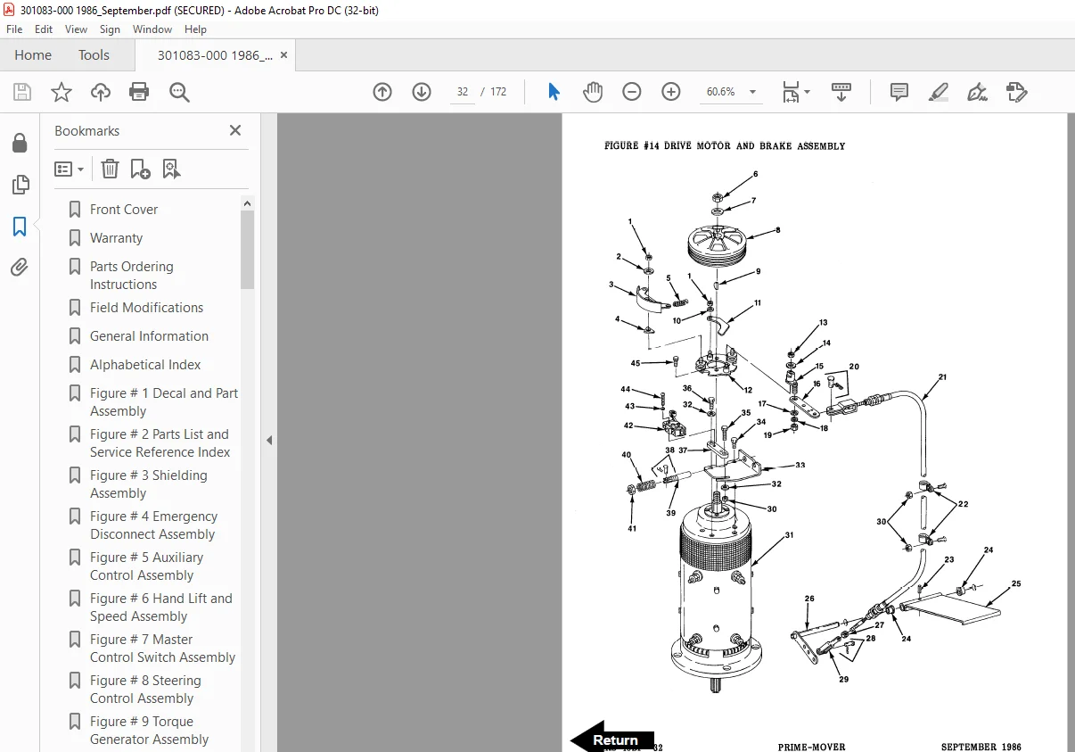
Figure # 14 Drive Motor and Brake Assembly 32
Figure # 15 Drive Motor Assembly 34
Figure # 16 Transmission Assembly 36
Figure # 17 Electrical Schematic 38
Figure # 18 Electrical Schematic Symbols 39
Figure # 19 Relay Wiring Harness Assembly 40
Figure # 20 Switch Relay Assembly 42
Figure # 21 Wiring Harness Assembly 44
Figure # 22 Wiring Assembly for Cold Storage 46
Figure # 23 2 Stage Mast Cable Assembly 48
Figure # 24 3 Stage Mast Cable Assembly 50
Figure # 25 Tilt with Sideshifter Cable Assembly 52
Figure # 26 Power Component Wiring 54
Figure # 27 SCR and Contactor Panel Assembly 56
Figure # 28 EV-1 SCR Control 58
Figure # 29 Transformer Assembly 60
Figure # 30 Rectifier Heat Sink Assembly 62
Figure # 31 GE Contactor Assembly 64
Figure # 32 GE Contactor Assembly 66
Figure # 33 Contactor Assembly 68
Figure # 34 Connector Assembly 70
Figure # 35 Warning Light Assembly 72
Figure # 36 Hydraulic Schematic 74
Figure # 37 Hydraulic Schematic Symbols 75
Figure # 38 Auxiliary Pump and Reservoir Assembly 76
Figure # 39 Hydraulic Reservoir Assembly 78
Figure # 40 Lift Pump and Motor Assembly 80
Figure # 41 Lift Pump and Motor Assembly 82
Figure # 42 Lift Motor Assembly 84
Figure # 43 24 Volt Lift Pump Assembly 86
Figure # 44 36 Volt Lift Pump Assembly 88
Figure # 45 Lift Control Valve Assembly 90
Figure # 46 Torque Generator and Filter Assembly 92
Figure # 47 Tube and Hose Assembly 94
Figure # 48 Auxiliary Control Valve Assembly 96
Figure # 49 2 Stage Cylinder and Reservoir Assembly 98
Figure # 50 2 Stage Cylinder Assembly100
Figure # 51 3 Stage Cylinders and Reservoir Assembly102
Figure # 52 3 Stage Staging Cylinder Assembly104
Figure # 53 3 Stage Freelift Cylinder Assembly106
Figure # 54 2 Stage Mast Hydraulic Hose Assembly108
Figure # 55 3 Stage Mast Hydraulic Hose Assembly110
Figure # 56 Tilt Cylinder and Related Parts112
Figure # 57 Tilt Cylinder Assembly114
Figure # 58 Sideshifter Cylinder with Tilt Assembly116
Figure # 59 Sideshifter Cylinder Assembly118
Figure # 60 Sideshifter Manifold Valve Assembly120
Figure # 61 2 Stage Mast Installation Assembly122
Figure # 62 2 Stage Inner Column Assembly124
Figure # 63 2 Stage Outer Column Assembly126
Figure # 64 2 Stage Cylinder Assembly and Related Parts128
Figure # 65 Lift Frame Assembly130
Figure # 66 Sideshifter Assembly132
Figure # 67 Fork Assembly134
Figure # 68 Three Stage Mast Installation Assembly136
Figure # 69 3 Stage Outer Column Assembly138
Figure # 70 3 Stage Intermediate Column Assembly140
Figure # 71 3 Stage Inner Column Assembly142
Figure # 72 3 Stage Freelift Cylinder Assembly and Related Parts144
Figure # 73 Main Frame and Load Wheel Assembly146
Figure # 74 Caster Assembly148
Figure # 75 Single Load Wheel Assembly150
Figure # 76 4″ High Outriggers Articulating Load Wheel Assembly152
Figure # 77 Articulating Load Wheel Assembly154
Figure # 78 Special Tools156
Numerical Index158
Back Cover172
IMAGES PREVIEW OF THE MANUAL:
S.M 6/24