BT Prime-Mover HMX/RMX Parts Manual Digital Manual PDF
$38.95
BT Prime-Mover HMX/RMX Parts Manual – PDF DOWNLOAD
Description
BT Prime-Mover HMX/RMX Parts Manual – PDF DOWNLOAD
FILE DETAILS:
BT Prime-Mover HMX/RMX Parts Manual – PDF DOWNLOAD
Language : English
Pages : 1840
Downloadable : Yes
File Type : PDF
302064-000 1994_February
302064-001 1994_April
302064-002 1994_September
302064-003 1994_November
302064-004 1995_January
302064-005 1995_June
302064-006 1995_September
302064-007 1995_December
302064-008 1996_December
302064-008 1997_May
302064-008 1997_December
302064-008 1998_September
302064-008 1999_October
302064-009 2001_August
302064-010 2002_February
304002-000 1994_November Designed and built for C&S Grocery Store
306753-000 1996_October Addendum, HMX-50 Designed and built for U.S.A Post Office
IMAGES PREVIEW OF THE MANUAL:
TABLE OF CONTENTS:
BT Prime-Mover HMX/RMX Parts Manual – PDF DOWNLOAD
Front Cover.................................................................................... 2
Parts Ordering Instructions.................................................................... 3
General Information............................................................................ 4
Alphabetical Index............................................................................. 5
Section 0.0.................................................................................... 7
Figure # 0.1............................................................................... 7
Section 1.0.................................................................................... 9
Figure # 1.1............................................................................... 9
Figure # 1.2............................................................................... 11
Figure # 1.3............................................................................... 13
Section 2.0.................................................................................... 15
Figure # 2.1............................................................................... 15
Figure # 2.2............................................................................... 16
Figure # 2.3............................................................................... 17
Figure # 2.4............................................................................... 19
Figure # 2.5............................................................................... 21
Figure # 2.6............................................................................... 23
Figure # 2.7............................................................................... 24
Figure # 2.8............................................................................... 25
Figure # 2.9............................................................................... 27
Figure # 2.10.............................................................................. 29
Figure # 2.11.............................................................................. 30
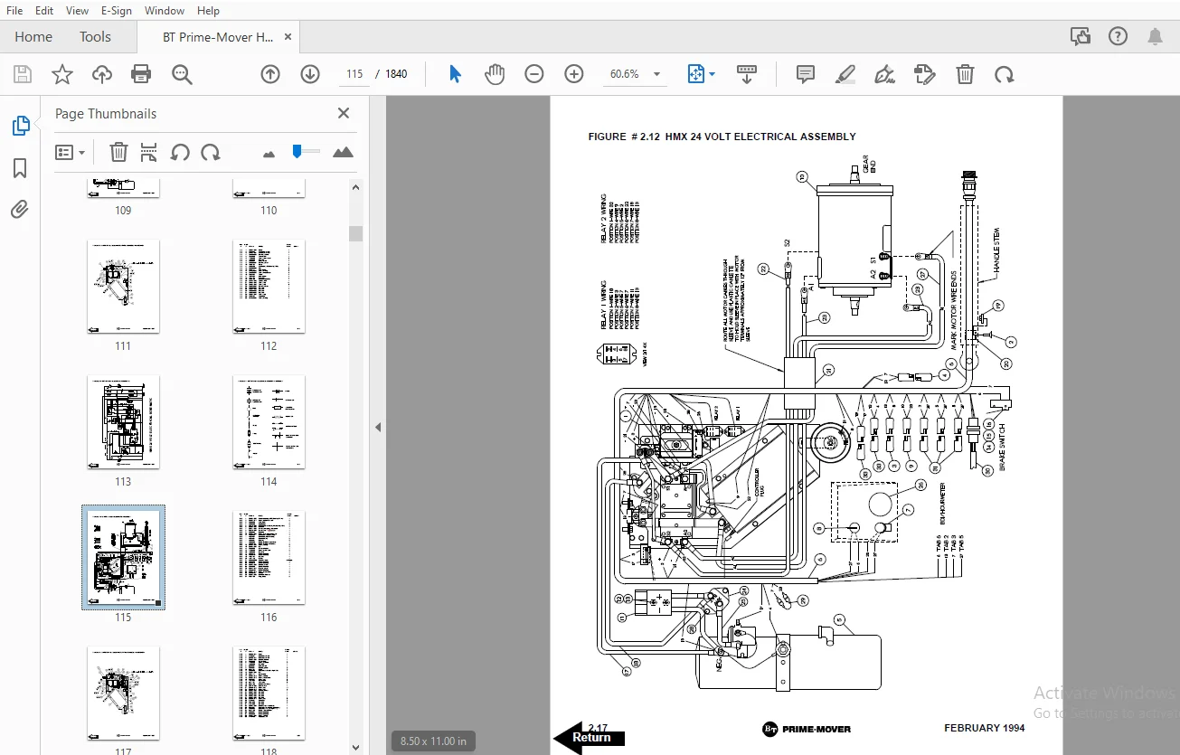
Figure # 2.12.............................................................................. 31
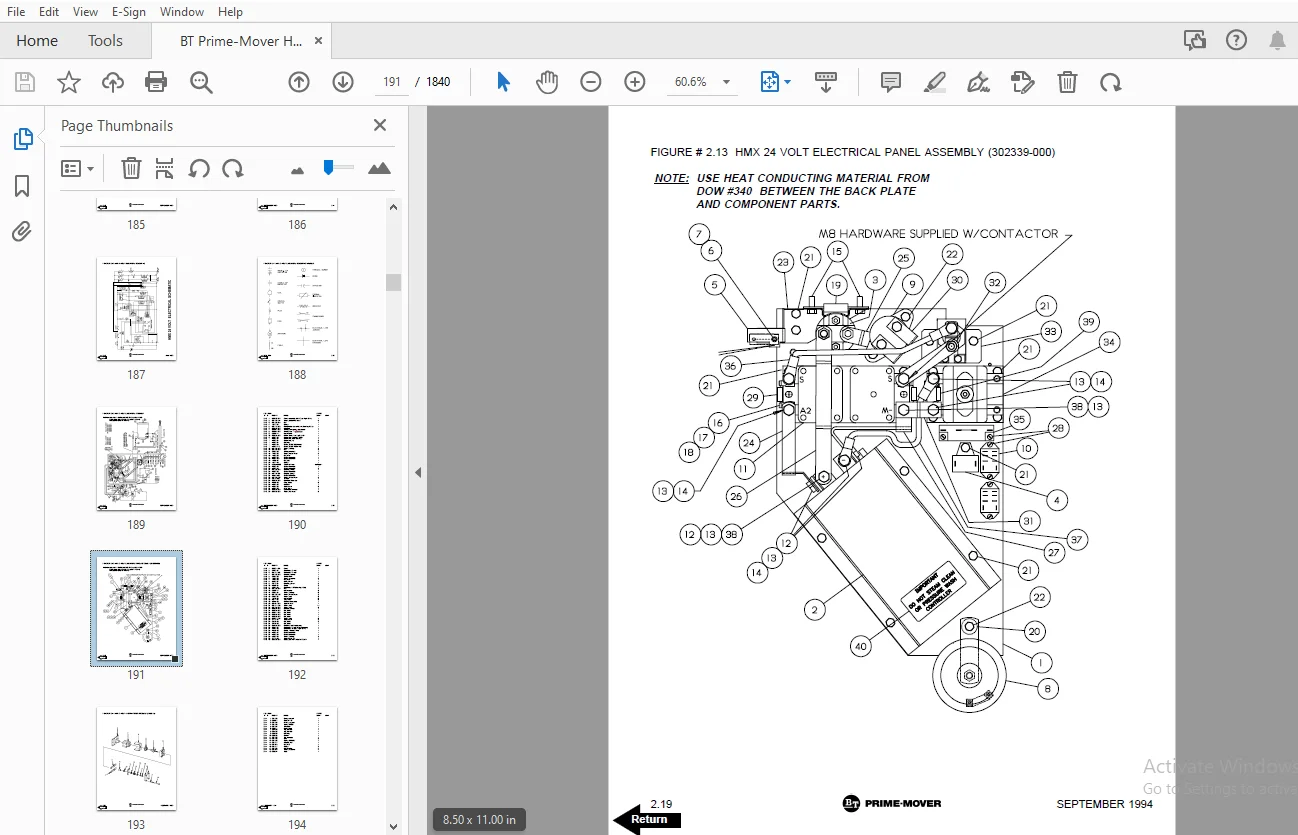
Figure # 2.13.............................................................................. 33
Figure # 2.14.............................................................................. 35
Figure # 2.15.............................................................................. 37
Figure # 2.16.............................................................................. 39
Figure # 2.17.............................................................................. 41
Figure # 2.18.............................................................................. 43
Figure # 2.19.............................................................................. 45
Figure # 2.20.............................................................................. 47
Section 3.0.................................................................................... 49
Figure # 3.1............................................................................... 49
Figure # 3.2............................................................................... 50
Figure # 3.3............................................................................... 51
Figure # 3.4............................................................................... 53
Section 4.0.................................................................................... 55
Figure # 4.1............................................................................... 55
Figure # 4.2............................................................................... 57
Figure # 4.3............................................................................... 59
Figure # 4.4............................................................................... 61
Figure # 4.5............................................................................... 63
Figure # 4.6............................................................................... 65
Figure # 4.7............................................................................... 67
Figure # 4.8............................................................................... 69
Figure # 4.9............................................................................... 71
Section 10.0................................................................................... 73
Figure # 10.1.............................................................................. 73
Numberical Index............................................................................... 76
Back Cover..................................................................................... 85
Front Cover.................................................................................... 86
Parts Ordering Instructions.................................................................... 87
General Information............................................................................ 88
Alphabetical Index............................................................................. 89
Section 0.0.................................................................................... 91
Figure # 0.1............................................................................... 91
Section 1.0.................................................................................... 93
Figure # 1.1............................................................................... 93
Figure # 1.2............................................................................... 95
Figure # 1.3............................................................................... 97
Section 2.0.................................................................................... 99
Figure # 2.1............................................................................... 99
Figure # 2.2............................................................................... 100
Figure # 2.3............................................................................... 101
Figure # 2.4............................................................................... 103
Figure # 2.5............................................................................... 105
Figure # 2.6............................................................................... 107
Figure # 2.7............................................................................... 108
Figure # 2.8............................................................................... 109
Figure # 2.9............................................................................... 111
Figure # 2.10.............................................................................. 113
Figure # 2.11.............................................................................. 114
Figure # 2.12.............................................................................. 115
Figure # 2.13.............................................................................. 117
Figure # 2.14.............................................................................. 119
Figure # 2.15.............................................................................. 121
Figure # 2.16.............................................................................. 123
Figure # 2.17.............................................................................. 125
Figure # 2.18.............................................................................. 127
Figure # 2.19.............................................................................. 129
Figure # 2.20.............................................................................. 131
Section 3.0.................................................................................... 133
Figure # 3.1............................................................................... 133
Figure # 3.2............................................................................... 134
Figure # 3.3............................................................................... 135
Figure # 3.4............................................................................... 137
Section 4.0.................................................................................... 139
Figure # 4.1............................................................................... 139
Figure # 4.2............................................................................... 141
Figure # 4.3............................................................................... 143
Figure # 4.4............................................................................... 145
Figure # 4.5............................................................................... 147
Figure # 4.6............................................................................... 149
Figure # 4.7............................................................................... 151
Figure # 4.8............................................................................... 153
Figure # 4.9............................................................................... 155
Section 10.0................................................................................... 157
Figure # 10.1.............................................................................. 157
Back Cover..................................................................................... 159
Front Cover.................................................................................... 160
Parts Ordering Instructions.................................................................... 161
General Information............................................................................ 162
Alphabetical Index............................................................................. 163
Section 0.0.................................................................................... 165
Figure # 0.1 Decals and Parts List Assembly................................................ 165
Section 1.0.................................................................................... 167
Figure # 1.1 Handle and Transmission Installation.......................................... 167
Figure # 1.2 Control Handle Head Assembly.................................................. 169
Figure # 1.3 Transmission Assembly......................................................... 171
Section 2.0.................................................................................... 173
Figure # 2.1 RMX 12 Volt Electrical Schematic.............................................. 173
Figure # 2.2 RMX 12 Volt Electrical Schematic Symbols...................................... 174
Figure # 2.3 RMX 12 Volt Electrical Assembly............................................... 175
Figure # 2.4 RMX 12 Volt Electrical Panel Assembly......................................... 177
Figure # 2.5 12 & 24 Volt Forward & Rearward Contactor Assembly............................ 179
Figure # 2.6 RMX 24 Volt Electrical Schematic.............................................. 181
Figure # 2.7 RMX 24 Volt Electrical Schematic Symbols...................................... 182
Figure # 2.8 RMX 24 Volt Electrical Assembly............................................... 183
Figure # 2.9 RMX 24 Volt Electrical Panel Assembly......................................... 185
Figure # 2.10 HMX 24 Volt Electrical Schematic............................................. 187
Figure # 2.11 HMX 24 Volt Electrical Schematic Symbols..................................... 188
Figure # 2.12 HMX 24 Volt Electrical Assembly.............................................. 189
Figure # 2.13 HMX 24 Volt Electrical Panel Assembly........................................ 191
Figure # 2.14 HMX 24 Volt 1A Contactor Assembly............................................ 193
Figure # 2.15 12/24 Volt Electrical Lift Interrupt......................................... 195
Figure # 2.16 Cold Storage Assembly........................................................ 197
Figure # 2.17 Pump Motor Assembly.......................................................... 199
Figure # 2.18 RMX 12 Volt Drive Motor Assembly............................................. 201
Figure # 2.19 RMX/HMX 24 Volt Drive Motor Assembly......................................... 203
Figure # 2.20 HMX 24 Volt Drive Motor Assembly............................................. 205
Section 3.0.................................................................................... 207
Figure # 3.1 Hydraulic Schematic........................................................... 207
Figure # 3.2 Hydraulic Schematic Symbols................................................... 208
Figure # 3.3 Hydraulic System Assembly..................................................... 209
Figure # 3.4 Hydraulic Pump and Motor...................................................... 211
Section 4.0.................................................................................... 213
Figure # 4.1 Frame Assembly................................................................ 213
Figure # 4.2 RMX Spring Loaded Caster Assembly............................................. 217
Figure # 4.3 Load Wheel Assembly........................................................... 219
Figure # 4.4 HMX Hand Rail Assembly........................................................ 221
Figure # 4.5 HMX Caster Torsion Rod Assembly............................................... 223
Figure # 4.6 HMX Caster Assembly........................................................... 225
Figure # 4.7 Battery Rollers and Frame Assembly............................................ 227
Figure # 4.8 Pallet Entry Rollers.......................................................... 229
Figure # 4.9 Removable Load Backrest....................................................... 231
Figure # 4.10 Shields and Guards........................................................... 233
Section 10.0................................................................................... 235
Figure # 10.1 Special Tools and Lubrications............................................... 235
Numerical Index................................................................................ 238
Back Cover..................................................................................... 247
Front Cover.................................................................................... 248
Parts Ordering Instructions.................................................................... 249
General Information............................................................................ 250
Alphabetical Index............................................................................. 251
Section 0.0.................................................................................... 253
Figure # 0.1............................................................................... 253
Section 1.0.................................................................................... 255
Figure # 1.1............................................................................... 255
Figure # 1.2............................................................................... 257
Figure # 1.3............................................................................... 259
Figure # 1.4............................................................................... 261
Section 2.0.................................................................................... 263
Figure # 2.1............................................................................... 263
Figure # 2.2............................................................................... 264
Figure # 2.3............................................................................... 265
Figure # 2.4............................................................................... 267
Figure # 2.5............................................................................... 269
Figure # 2.6............................................................................... 271
Figure # 2.7............................................................................... 272
Figure # 2.8............................................................................... 273
Figure # 2.9............................................................................... 275
Figure # 2.10.............................................................................. 277
Figure # 2.11.............................................................................. 278
Figure # 2.12.............................................................................. 279
Figure # 2.13.............................................................................. 281
Figure # 2.14.............................................................................. 283
Figure # 2.15.............................................................................. 285
Figure # 2.16.............................................................................. 287
Figure # 2.17.............................................................................. 289
Figure # 2.18.............................................................................. 291
Figure # 2.19.............................................................................. 293
Section 3.0.................................................................................... 295
Figure # 3.1............................................................................... 295
Figure # 3.2............................................................................... 296
Figure # 3.3............................................................................... 297
Figure # 3.4............................................................................... 299
Section 4.0.................................................................................... 301
Figure # 4.1............................................................................... 301
Figure # 4.2............................................................................... 305
Figure # 4.3............................................................................... 307
Figure # 4.4............................................................................... 309
Figure # 4.5............................................................................... 311
Figure # 4.6............................................................................... 313
Figure # 4.7............................................................................... 315
Figure # 4.8............................................................................... 317
Figure # 4.9............................................................................... 319
Figure # 4.10.............................................................................. 321
Figure # 4.11.............................................................................. 323
Section 10.0................................................................................... 325
Figure # 10.1.............................................................................. 325
Numerical Index................................................................................ 328
Back Cover..................................................................................... 337
Front Cover.................................................................................... 338
Parts Ordering Instructions.................................................................... 339
General Information............................................................................ 340
Alphabetical Index............................................................................. 342
Figure # 0.1 Decals and Parts List Assembly.................................................... 343
Figure # 1.1 Handle and Transmission Installation.............................................. 345
Figure # 1.2 Walk Along Knob Control Handle Head Assembly...................................... 347
Figure # 1.3 Transmission Assembly............................................................. 349
Figure # 2.1 Electrical Schematic.............................................................. 351
Figure # 2.2 Electrical Schematic Symbols...................................................... 352
Figure # 2.3 Electrical Assembly............................................................... 353
Figure # 2.4 Electrical Panel Assembly......................................................... 355
Figure # 2.5 Forward & Rearward Contactor Assembly............................................. 357
Figure # 2.6 1A Contactor Assembly............................................................. 359
Figure # 2.7 Pump Motor Assembly............................................................... 361
Figure # 2.8 Drive Motor Assembly.............................................................. 363
Figure # 3.1 Hydraulic Schematic............................................................... 365
Figure # 3.2 Hydraulic Schematic Symbols....................................................... 366
Figure # 3.3 Hydraulic System Assembly......................................................... 367
Figure # 3.4 Hydraulic Pump and Motor.......................................................... 369
Figure # 4.1 Frame Assembly.................................................................... 371
Figure # 4.2 Load Wheel Assembly............................................................... 373
Figure # 4.3 Hand Rail Assembly................................................................ 375
Figure # 4.4 Caster Torsion Rod Assembly....................................................... 377
Figure # 4.5 Caster Assembly................................................................... 379
Figure # 4.6 Battery Rollers and Frame Assembly................................................ 381
Figure # 4.7 Shields and Guards................................................................ 383
Figure # 4.8 Tilting Package Guard Assembly.................................................... 385
Figure # 10.1 Special Tools and Lubrications................................................... 387
Numerical Index................................................................................ 390
Back Cover..................................................................................... 397
Front Cover.................................................................................... 398
Parts Ordering Instructions.................................................................... 399
General Information............................................................................ 400
Alphabetical Index............................................................................. 401
Section 0.0.................................................................................... 403
Figure # 0.1 Decals and Parts List Assembly................................................ 403
Section 1.0.................................................................................... 405
Figure # 1.1 Handle and Transmission Installation.......................................... 405
Figure # 1.2 Control Handle Head Assembly.................................................. 407
Figure # 1.3 Walk Along Knob Control Handle Head Assembly.................................. 409
Figure # 1.4 Transmission Assembly......................................................... 411
Section 2.0.................................................................................... 413
Figure # 2.1 RMX 12 Volt Electrical Schematic.............................................. 413
Figure # 2.2 RMX 12 Volt Electrical Schematic Symbols...................................... 414
Figure # 2.3 RMX 12 Volt Electrical Assembly............................................... 415
Figure # 2.4 RMX 12 Volt Electrical Panel Assembly......................................... 417
Figure # 2.5 12 & 24 Volt Forward & Rearward Contactor Assembly............................ 419
Figure # 2.6 RMX 24 Volt Electrical Schematic.............................................. 421
Figure # 2.7 RMX 24 Volt Electrical Schematic Symbols...................................... 422
Figure # 2.8 RMX 24 Volt Electrical Assembly............................................... 423
Figure # 2.9 RMX 24 Volt Electrical Panel Assembly......................................... 425
Figure # 2.10 HMX 24 Volt Electrical Schematic............................................. 427
Figure # 2.11 HMX 24 Volt Electrical Schematic Symbols..................................... 428
Figure # 2.12 HMX 24 Volt Electrical Assembly.............................................. 429
Figure # 2.13 HMX 24 Volt Electrical Panel Assembly........................................ 431
Figure # 2.14 HMX 24 Volt 1A Contactor Assembly............................................ 433
Figure # 2.15 12/24 Volt Electrical Lift Interrupt......................................... 435
Figure # 2.16 Cold Storage Assembly........................................................ 437
Figure # 2.17 Pump Motor Assembly.......................................................... 439
Figure # 2.18 RMX 12 Volt Drive Motor Assembly............................................. 441
Figure # 2.19 RMX/HMX 24 Volt Drive Motor Assembly......................................... 443
Section 3.0.................................................................................... 445
Figure # 3.1 Lift Hydraulic Schematic...................................................... 445
Figure # 3.2 Hydraulic Schematic Symbols................................................... 446
Figure # 3.3 Hydraulic System Assembly..................................................... 447
Figure # 3.4 Hydraulic Pump and Motor Assembly............................................. 449
Section 4.0.................................................................................... 451
Figure # 4.1 Frame Assembly................................................................ 451
Figure # 4.2 RMX Spring Loaded Caster Assembly............................................. 455
Figure # 4.3 Load Wheel Assembly........................................................... 457
Figure # 4.4 HMX Hand Rail Assembly........................................................ 459
Figure # 4.5 HMX Caster Torsion Rod Assembly............................................... 461
Figure # 4.6 HMX Caster Assembly........................................................... 463
Figure # 4.7 Battery Rollers and Frame Assembly............................................ 465
Figure # 4.8 Pallet Entry Rollers.......................................................... 467
Figure # 4.9 Removable Load Backrest....................................................... 469
Figure # 4.10 Shields and Guards........................................................... 471
Figure # 4.11 Tilting Package Guard Assembly............................................... 473
Section 10.0................................................................................... 475
Figure # 10.1 Special Tools and Lubrications............................................... 475
Numerical Index................................................................................ 478
Back Cover..................................................................................... 487
Front Cover.................................................................................... 488
Parts Ordering Instructions.................................................................... 489
General Information............................................................................ 490
Alphabetical Index............................................................................. 491
Section 0.0.................................................................................... 493
Figure # 0.1 Decals and Parts List Assembly................................................ 493
Section 1.0.................................................................................... 495
Figure # 1.1 Handle and Transmission Installation.......................................... 495
Figure # 1.2 Control Handle Head Assembly.................................................. 497
Figure # 1.3 Walk Along Knob Control Handle Head Assembly.................................. 499
Figure # 1.4 Transmission Assembly......................................................... 501
Figure # 1.5 Drive Wheel Assembly.......................................................... 503
Section 2.0.................................................................................... 505
Figure # 2.1 RMX 12 Volt Electrical Schematic.............................................. 505
Figure # 2.2 RMX 12 Volt Electrical Schematic Symbols...................................... 506
Figure # 2.3 RMX 12 Volt Electrical Assembly............................................... 507
Figure # 2.4 RMX 12 Volt Electrical Panel Assembly......................................... 509
Figure # 2.5 Forward & Rearward Contactor Assembly......................................... 511
Figure # 2.6 RMX 24 Volt Electrical Schematic.............................................. 513
Figure # 2.7 RMX 24 Volt Electrical Schematic Symbols...................................... 514
Figure # 2.8 RMX 24 Volt Electrical Assembly............................................... 515
Figure # 2.9 RMX 24 Volt Electrical Panel Assembly......................................... 517
Figure # 2.10 HMX 24 Volt Electrical Schematic............................................. 519
Figure # 2.11 HMX 24 Volt Electrical Schematic Symbols..................................... 520
Figure # 2.12 HMX 24 Volt Electrical Assembly.............................................. 521
Figure # 2.13 HMX 24 Volt Electrical Panel Assembly........................................ 523
Figure # 2.14 HMX 24 Volt 1A Contactor Assembly............................................ 525
Figure # 2.15 12/24 Volt Electrical Lift Interrupt......................................... 527
Figure # 2.16 Cold Storage Assembly........................................................ 529
Figure # 2.17 Pump Motor Assembly.......................................................... 531
Figure # 2.18 RMX 12 Volt Drive Motor Assembly............................................. 533
Figure # 2.19 RMX/HMX 24 Volt Drive Motor Assembly......................................... 535
Figure # 2.20 Power Connector Assembly..................................................... 537
Section 3.0.................................................................................... 539
Figure # 3.1 Lift Hydraulic Schematic...................................................... 539
Figure # 3.2 Hydraulic Schematic Symbols................................................... 540
Figure # 3.3 Hydraulic System Assembly..................................................... 541
Figure # 3.4 Hydraulic Pump and Motor Assembly............................................. 543
Section 4.0.................................................................................... 545
Figure # 4.1 Frame Assembly................................................................ 545
Figure # 4.2 RMX Spring Loaded Caster Assembly............................................. 549
Figure # 4.3 Load Wheel Assembly........................................................... 551
Figure # 4.4 HMX Hand Rail Assembly........................................................ 553
Figure # 4.5 HMX Caster Torsion Rod Assembly............................................... 555
Figure # 4.6 HMX Caster Assembly........................................................... 557
Figure # 4.7 Battery Rollers and Frame Assembly............................................ 559
Figure # 4.8 Pallet Entry Rollers.......................................................... 561
Figure # 4.9 Removable Load Backrest....................................................... 563
Figure # 4.10 Shields and Guards........................................................... 565
Figure # 4.11 Tilting Package Guard Assembly............................................... 567
Section 10.0................................................................................... 569
Figure # 10.1 Special Tools and Lubrications............................................... 569
Numerical Index................................................................................ 572
Back Cover..................................................................................... 582
Front Cover.................................................................................... 583
Parts Ordering Instructions.................................................................... 584
General Information............................................................................ 585
Alphabetical Index............................................................................. 586
Section 0.0.................................................................................... 588
Figure # 0.1 Decals and Parts List Assembly................................................ 588
Section 1.0.................................................................................... 590
Figure # 1.1 Handle and Transmission Installation.......................................... 590
Figure # 1.2 Control Handle Head Assembly.................................................. 592
Figure # 1.3 Walk Along Knob Control Handle Head Assembly.................................. 594
Figure # 1.4 Transmission Assembly......................................................... 596
Figure # 1.5 Drive Wheel Assembly.......................................................... 598
Section 2.0.................................................................................... 600
Figure # 2.1 RMX 12 Volt Electrical Schematic.............................................. 600
Figure # 2.2 RMX 12 Volt Electrical Schematic Symbols...................................... 601
Figure # 2.3 RMX 12 Volt Electrical Assembly............................................... 602
Figure # 2.4 RMX 12 Volt Electrical Panel Assembly......................................... 604
Figure # 2.5 Contactor Assembly, Forward & Rearward........................................ 606
Figure # 2.6 RMX 24 Volt Electrical Schematic.............................................. 608
Figure # 2.7 RMX 24 Volt Electrical Schematic Symbols...................................... 609
Figure # 2.8 RMX 24 Volt Electrical Assembly............................................... 610
Figure # 2.9 RMX 24 Volt Electrical Panel Assembly......................................... 612
Figure # 2.10 HMX 24 Volt Electrical Schematic............................................. 614
Figure # 2.11 HMX 24 Volt Electrical Schematic Symbols..................................... 615
Figure # 2.12 HMX 24 Volt Electrical Assembly.............................................. 616
Figure # 2.13 HMX 24 Volt Electrical Panel Assembly........................................ 618
Figure # 2.14 HMX 24 Volt 1A Contactor Assembly............................................ 620
Figure # 2.15 12/24 Volt Electrical Lift Interrupt......................................... 622
Figure # 2.16 Cold Storage Assembly........................................................ 624
Figure # 2.17 Motor Assembly, Pump......................................................... 626
Figure # 2.18 RMX 12 Volt Drive Motor Assembly............................................. 628
Figure # 2.19 RMX/HMX 24 Volt Drive Motor Assembly......................................... 630
Figure # 2.20 Power Connector Assembly..................................................... 632
Section 3.0.................................................................................... 634
Figure # 3.1 Hydraulic Schematic........................................................... 634
Figure # 3.2 Hydraulic Schematic Symbols .................................................. 635
Figure # 3.3 Hydraulic System Assembly..................................................... 636
Figure # 3.4 Hydraulic Pump and Motor Assembly............................................. 638
Section 4.0.................................................................................... 640
Figure # 4.1 Frame Assembly................................................................ 640
Figure # 4.2 RMX Spring Loaded Caster Assembly............................................. 644
Figure # 4.3 Wheel Assembly, Load.......................................................... 646
Figure # 4.4 HMX Hand Rail Assembly........................................................ 648
Figure # 4.5 HMX Caster Torsion Rod Assembly............................................... 650
Figure # 4.6 Caster Assembly............................................................... 652
Figure # 4.7 Battery Rollers and Frame Assembly............................................ 654
Figure # 4.8 Pallet Entry Rollers.......................................................... 656
Figure # 4.9 Removable Load Backrest....................................................... 658
Figure # 4.10 Shields and Guards........................................................... 660
Figure # 4.11 Tilting Packing Guard Assembly............................................... 662
Section 10.0................................................................................... 664
Figure # 10.0 Special Tools and Lubrications............................................... 664
Numerical Index................................................................................ 667
Back Cover..................................................................................... 676
Addendum, HMX-50............................................................................... 677
Fig02010 HMX 24 Volt Electrical Schematic...................................................... 679
Fig02012 HMX 24 Volt Electrical Assembly....................................................... 681
Front Cover.................................................................................... 683
Parts Ordering Instructions.................................................................... 684
General Information............................................................................ 685
Alphabetical Index............................................................................. 686
Section 0.0.................................................................................... 688
Figure # 0.1 Decals and Parts List Assembly................................................ 688
Section 1.0.................................................................................... 690
Figure # 1.1 Handle and Transmission Installation.......................................... 690
Figure # 1.2 Control Handle Head Assembly.................................................. 692
Figure # 1.3 Walk Along Knob Control Handle Head Assembly.................................. 694
Figure # 1.4 Transmission Assembly......................................................... 696
Figure # 1.5 Drive Wheel Assembly.......................................................... 698
Section 2.0.................................................................................... 700
Figure # 2.1 RMX 12 Volt Electrical Schematic.............................................. 700
Figure # 2.2 RMX 12 Volt Electrical Schematic Symbols...................................... 701
Figure # 2.3 RMX 12 Volt Electrical Assembly............................................... 702
Figure # 2.4 RMX 12 Volt Electrical Panel Assembly......................................... 704
Figure # 2.5 Contactor Assembly, Forward & Rearward........................................ 706
Figure # 2.6 RMX 24 Volt Electrical Schematic.............................................. 708
Figure # 2.7 RMX 24 Volt Electrical Schematic Symbols...................................... 709
Figure # 2.8 RMX 24 Volt Electrical Assembly............................................... 710
Figure # 2.9 RMX 24 Volt Electrical Panel Assembly......................................... 712
Figure # 2.10 HMX 24 Volt Electrical Schematic............................................. 714
Figure # 2.11 HMX 24 Volt Electrical Schematic Symbols..................................... 715
Figure # 2.12 HMX 24 Volt Electrical Assembly.............................................. 716
Figure # 2.13 HMX 24 Volt Electrical Panel Assembly........................................ 718
Figure # 2.14 HMX 24 Volt 1A Contactor Assembly............................................ 720
Figure # 2.15 12/24 Volt Electrical Lift Interrupt......................................... 722
Figure # 2.16 Cold Storage Assembly........................................................ 724
Figure # 2.17 Motor Assembly, Pump......................................................... 726
Figure # 2.18 RMX 12 Volt Drive Motor Assembly............................................. 728
Figure # 2.19 RMX/HMX 24 Volt Drive Motor Assembly......................................... 730
Figure # 2.20 Power Connector Assembly..................................................... 732
Section 3.0.................................................................................... 734
Figure # 3.1 Hydraulic Schematic........................................................... 734
Figure # 3.2 Hydraulic Schematic Symbols................................................... 735
Figure # 3.3 Hydraulic System Assembly..................................................... 736
Figure # 3.4 Hydraulic Pump and Motor Assembly............................................. 738
Section 4.0.................................................................................... 740
Figure # 4.1 Frame Assembly................................................................ 740
Figure # 4.2 RMX Spring Loaded Caster Assembly............................................. 744
Figure # 4.3 Wheel Assembly, Load.......................................................... 746
Figure # 4.4 HMX Hand Rail Assembly........................................................ 748
Figure # 4.5 HMX Caster Torsion Rod Assembly............................................... 750
Figure # 4.6 Caster Assembly............................................................... 752
Figure # 4.7 Battery Rollers and Frame Assembly............................................ 754
Figure # 4.8 Pallet Entry Rollers.......................................................... 756
Figure # 4.9 Removable Load Backrest....................................................... 758
Figure # 4.10 Shields and Guards........................................................... 760
Figure # 4.11 Tilting Package Guard Assembly............................................... 762
Section 10.0................................................................................... 764
Figure # 10.0 Special Tools and Lubrications............................................... 764
Numerical Index................................................................................ 767
Back Cover..................................................................................... 776
Front Cover.................................................................................... 777
Parts Ordering Instructions.................................................................... 778
General Information............................................................................ 779
Index.......................................................................................... 781
0000 - Chassis................................................................................. 784
0300-000 Frame/Chassis..................................................................... 785
0340-007 Inspection Covers (Shields & Guards).............................................. 789
0390-003 Battery Compartment Parts......................................................... 791
0640-016 Drivers Controls (Speed & Direction).............................................. 793
0640-020 Drivers Controls (Hand Rail)...................................................... 795
0840-013 Driver Protection................................................................. 797
0850-004 Signs, Warnings................................................................... 799
1000 - Drive Motor............................................................................. 800
1700-006 Electrical Drive Motor (12 Volt).................................................. 801
1700-007 Electrical Drive Motor (24 Volt).................................................. 803
2000 - Drive Gear/Transmission................................................................. 803
2550-002 Mechanical Drive Gear Unit........................................................ 805
3000 - Brake/Wheel System...................................................................... 806
3300-002 Parking Brake System.............................................................. 807
3360-000 Brake Drum/Disc Assembly.......................................................... 809
3530-001 Drive Wheel....................................................................... 811
3540-004 Support/Swivel Wheel.............................................................. 813
3550-006 Fork/Support Arm/Outrigger Wheels................................................. 815
3560-002 Stabilizer Wheel.................................................................. 817
3560-003 Stabilizer Wheel (Spring Loaded).................................................. 819
3580-000 Guide Wheels...................................................................... 821
4000 - Steering System......................................................................... 822
4110-019 Steering Arm/Wheel................................................................ 823
4110-020 Steering Arm/Wheel................................................................ 825
4180-001 Steering/Radial Bearing........................................................... 827
5000 - Electrical System....................................................................... 828
5100-000 General Electrical Compartments (RMX 12 Volt)..................................... 829
5100-001 General Electrical Compartments (RMX 24 Volt)..................................... 831
5100-002 General Electrical Compartments (HMX 24 Volt)..................................... 833
5100-003 General Electrical Compartments (RMX 12 Volt)..................................... 835
5100-004 General Electrical Compartments (RMX 24 Volt)..................................... 837
5100-005 General Electrical Compartments (HMX 24 Volt)..................................... 839
5160-013 General Alarm Signal.............................................................. 841
5190-014 Battery Cut Out Contactor/Plug (Battery Connector)................................ 843
5230-003 Voltage/Battery Indicator......................................................... 845
5290-001 Hourmeter/Speedometer............................................................. 847
5310-017 Start/Stop Switch................................................................. 849
5330-011 Speed Controls.................................................................... 851
5390-003 Control Cables/Harness............................................................ 853
5440-001 Direction Contactors.............................................................. 855
5450-000 Speed Contactors (1A)............................................................. 857
5510-011 Micro Switches.................................................................... 859
5810-012 Pump Motor (12 Volt).............................................................. 861
5810-013 Pump Motor (24 Volt).............................................................. 863
6000 - Hydraulic System........................................................................ 864
6100-020 Hydraulic Pump.................................................................... 865
6125-017 Hoses, Pipes, Connections, Mounting Points........................................ 867
7000 - Operating Function - Lifting Mast/Cylinder.............................................. 868
7310-011 Lift Cylinder..................................................................... 869
7400-000 Lift and Carrying Devices (Tilting Package Guard)................................. 871
7400-001 Lift and Carrying Devices (Removable Load Backrest)............................... 873
9000 - Options/Attachments..................................................................... 874
9660-001 Electrical Heater................................................................. 875
9999-000 Special Tools and Lubrications.................................................... 877
Back Cover..................................................................................... 878
Front Cover.................................................................................... 879
Parts Ordering Instructions.................................................................... 880
General Information............................................................................ 881
Index.......................................................................................... 883
0000 Chassis................................................................................... 886
0300-000 Frame/Chassis..................................................................... 887
0340-007 Inspection Covers (Shields & Guards).............................................. 891
0340-018 Inspection Covers ("EE" Electrical Box)........................................... 893
0340-019 Inspection Covers (Splash Guard).................................................. 895
0390-003 Battery Compartment Parts......................................................... 897
0640-016 Drivers Controls (Speed & Direction).............................................. 899
0640-020 Drivers Controls (Hand Rail)...................................................... 901
0640-015 Drivers Protection (Reverser)..................................................... 903
0850-004 Signs, Warnings................................................................... 905
1000 Drive Motor............................................................................... 906
1700-004 Electrical Drive Motor (24 Volt 300/400 Amp Traction System)...................... 907
1700-006 Electrical Drive Motor (12 Volt).................................................. 909
2000 Drive Gear/Transmission................................................................... 910
2550-002 Mechanical Drive Gear Unit........................................................ 911
3000 Brake/Wheel System........................................................................ 912
3300-002 Parking Brake System.............................................................. 913
3360-000 Brake Drum/Disc Assembly.......................................................... 915
3530-001 Drive Wheel....................................................................... 917
3540-004 Support/Swivel Wheel.............................................................. 919
3550-006 Fork/Support Arm/Outrigger Wheels................................................. 921
3560-002 Stabilizer Wheel.................................................................. 923
3560-003 Stabilizer Wheel (Spring Loaded).................................................. 925
3580-000 Guide Wheels...................................................................... 927
4000 Steering System........................................................................... 928
4110-010 Steering Arm/Wheel (Tiller Arm)................................................... 929
4110-011 Steering Arm/Wheel (Control Head Assembly)........................................ 931
4110-020 Steering Arm/Wheel (Walk Along Knob Control Head Assembly)........................ 933
4180-001 Steering/Radial Bearing........................................................... 935
5000 Electrical System......................................................................... 936
5160-013 General Alarm Signal.............................................................. 937
5180-004 Current Collector, Cable Drum..................................................... 939
5190-011 Battery Cut Out Contactor/Plug (300/400 Amp Traction System)...................... 941
5190-014 Battery Cut Out Contactor/Plug (Battery Connector)................................ 943
5230-003 Voltage/Battery Indicator......................................................... 945
5290-001 Hourmeter/Speedometer............................................................. 947
5310-017 Start/Stop Switch................................................................. 949
5330-011 Speed Controls.................................................................... 951
5360-001 Relay, Electrical Modules (12 Volt)............................................... 953
5390-003 Control Cables/Harness............................................................ 955
5390-031 Control Cables/Harness (24 Volt, 300 Amp System).................................. 957
5390-032 Control Cables/Harness (12 Volt RMX).............................................. 959
5390-033 Control Cables/Harness (24 Volt, 400 Amp System).................................. 961
5430-018 Motor Cables, Resistors (24 Volt, 300 Amp System)................................. 963
5430-019 Motor Cables, Resistors (12 Volt RMX)............................................. 965
5430-021 Motor Cables, Resistors (24 Volt, 400 Amp System)................................. 967
5435-003 Contactor Panel (12 Volt, RMX).................................................... 969
5440-001 Direction Contactors.............................................................. 971
5460-018 Transistor Panel (24 Volt, 300 Amp System)........................................ 973
5460-019 Transistor Panel (24 Volt, 400 Amp System)........................................ 975
5460-020 Transistor Panel (12 Volt)........................................................ 977
5510-011 Micro Switches.................................................................... 979
5810-012 Pump Motor (12 Volt).............................................................. 981
5810-013 Pump Motor (24 Volt).............................................................. 983
6000 Hydraulic System.......................................................................... 984
6100-020 Hydraulic Pump.................................................................... 985
6125-017 Hoses, Pipes, Connections, Mounting Points........................................ 987
7000 Operating Function - Lifting Mast/Cylinder................................................ 988
7310-011 Lift Cylinder..................................................................... 989
7400-000 Lift and Carrying Devices (Tilting Package Guard)................................. 991
7400-001 Lift and Carrying Devices (Removable Load Backrest)............................... 993
9000 Options/Attachments....................................................................... 994
9660-007 Electrical Heater (24 Volt)....................................................... 995
9660-008 Electrical Heater................................................................. 997
9910-000 Electrical Controllers (Handset).................................................. 999
Back Cover.....................................................................................1000
Front Cover....................................................................................1001
Parts Ordering Instructions....................................................................1002
General Information............................................................................1003
Index..........................................................................................1005
Section 0000 - Chassis.........................................................................1005
Figure # 0300-000 Frame/Chassis............................................................1009
Figure # 0340-007 Inspection Covers (Shields & Guards).....................................1013
Figure # 0340-018 Inspection Covers ("EE" Electrical Box)..................................1015
Figure # 0340-019 Inspection Covers (Splash Guard).........................................1017
Figure # 0390-003 Battery Compartment Parts................................................1019
Figure # 0640-016 Drivers Controls (Speed & Direction).....................................1021
Figure # 0640-020 Drivers Controls (Hand Rail).............................................1023
Figure # 0840-015 Driver Protection (Reverser).............................................1025
Figure # 0850-004 Signs, Warnings..........................................................1027
Section 1000 - Drive Motor.....................................................................1027
Figure # 1700-004 Electrical Drive Motor...................................................1029
Figure # 1700-006 Electrical Drive Motor...................................................1031
Section 2000 - Drive Gear/Transmission.........................................................1031
Figure # 2550-002 Mechanical Drive Gear Unit...............................................1033
Section 3000 - Brake/Wheel System..............................................................1033
Figure # 3300-002 Parking Brake System.....................................................1035
Figure # 3360-000 Brake Drum/Disc Assembly.................................................1037
Figure # 3530-001 Drive Wheel..............................................................1039
Figure # 3540-004 Support/Swivel Wheel.....................................................1041
Figure # 3550-006 Fork/Support Arm/Outrigger Wheels........................................1043
Figure # 3560-002 Stabilizer Wheel.........................................................1045
Figure # 3560-003 Stabilizer Wheel (Spring Loaded).........................................1047
Figure # 3580-000 Guide Wheels.............................................................1049
Section 4000 - Steering System.................................................................1049
Figure # 4110-000 Steering Arm/Wheel (Tiller Arm)..........................................1051
Figure # 4110-011 Steering Arm/Wheel (Control Head Assembly)...............................1053
Figure # 4110-020 Steering Arm/Wheel (Walk Along Knob Control Head Assembly)...............1055
Figure # 4180-001 Steering/Radial Bearing..................................................1057
Section 5000 - Electrical System...............................................................1057
Figure # 5160-013 General Alarm Signal.....................................................1059
Figure # 5180-004 Current Collector, Cable Drum............................................1061
Figure # 5190-011 Battery Cut Out Contactor/Plug...........................................1063
Figure # 5190-014 Battery Cut Out Contactor/Plug (Battery Connector).......................1065
Figure # 5230-003 Voltage/Battery Indicator................................................1067
Figure # 5290-001 Hourmeter/Speedometer....................................................1069
Figure # 5310-025 Start/Stop Switch........................................................1071
Figure # 5330-011 Speed Controls...........................................................1073
Figure # 5360-001 Relay, Electrical Modules................................................1075
Figure # 5390-003 Control Cables/Harness (Handle Head).....................................1077
Figure # 5390-031 Control Cables/Harness (24 Volt, 300 Amp System).........................1079
Figure # 5390-032 Control Cables/Harness (12 Volt RMX).....................................1081
Figure # 5390-033 Control Cables/Harness (24 Volt, 400 Amp System).........................1083
Figure # 5430-018 Motor Cables, Resistors (24 Volt, 300 Amp System)........................1085
Figure # 5430-019 Motor Cables, Resistors (12 Volt RMX)....................................1087
Figure # 5430-021 Motor Cables, Resistors (24 Volt, 400 Amp System)........................1089
Figure # 5435-003 Contactor Panel (12 Volt, RMX)...........................................1091
Figure # 5440-001 Direction Contactors.....................................................1093
Figure # 5460-018 Transistor Panel (24 Volt, 300 Amp System)...............................1095
Figure # 5460-019 Transistor Panel (24 Volt, 400 Amp System)...............................1097
Figure # 5460-020 Transistor Panel (12 Volt)...............................................1099
Figure # 5510-011 Micro Switches...........................................................1101
Figure # 5810-012 Pump Motor (12 Volt).....................................................1103
Figure # 5810-013 Pump Motor (24 Volt).....................................................1105
Section 6000 - Hydraulic System................................................................1105
Figure # 6100-002 Hydraulic Pump...........................................................1107
Figure # 6100-020 Hydraulic Pump...........................................................1109
Figure # 6125-017 Hoses, Pipes, Connections, Mounting Points...............................1111
Section 7000 - Operating Function - Lifting Mast/Cylinder......................................1111
Figure # 7310-011 Lift Cylinder............................................................1113
Figure # 7400-000 Lift and Carrying Devices (Tilting Package Guard)........................1115
Figure # 7400-001 Lift and Carrying Devices (Removable Load Backrest)......................1117
Section 9000 - Options/Attachments.............................................................1117
Figure # 9660-007 Electrical Heater (24 Volt)..............................................1119
Figure # 9660-008 Electrical Heater........................................................1121
Figure # 9910-000 Electrical Controllers (Handset).........................................1123
Back Cover.....................................................................................1124
Front Cover....................................................................................1125
Parts Ordering Instructions....................................................................1126
General Information............................................................................1127
Index..........................................................................................1130
0000 Chassis...................................................................................1135
0300-000 Frame / Chassis...................................................................1137
0340-000 Inspection covers (Shields & guards)..............................................1141
0341-000 Inspection covers (“EE” electrical box)...........................................1143
0342-000 Inspection covers (Splash guard)..................................................1145
0390-000 Battery compartment parts.........................................................1147
0640-000 Drivers controls (Speed & direction)..............................................1149
0641-000 Drivers controls (Hand rail)......................................................1151
0840-000 Driver protection (Reverser)......................................................1153
0850-000 Signs, warnings...................................................................1155
1000 Motors....................................................................................1157
1750-000 Pump motor (12 Volt)..............................................................1159
1750-100 Pump motor (24 Volt)..............................................................1161
1760-000 Drive motor (12 Volt).............................................................1163
1760-101 Drive motor (24 Volt).............................................................1165
2000 Transmission/Drive Gear...................................................................1167
2550-000 Mechanical drive gear unit........................................................1169
3000 Brake/Wheel System........................................................................1171
3300-000 Parking brake system..............................................................1173
3360-000 Brake drum / disc assembly........................................................1175
3530-000 Drive wheel.......................................................................1177
3540-000 Support / swivel wheel............................................................1179
3550-000 Load wheels.......................................................................1181
3560-000 Caster wheel......................................................................1183
3560-100 Caster wheel, spring Loaded.......................................................1185
3580-000 Guide wheels......................................................................1187
4000 Steering System...........................................................................1189
4110-001 Steering arm / wheel (Tiler arm) Serial Number 27324000 - UP......................1191
4111-000 Steering arm / wheel (Control head assembly)......................................1193
4111-100 Steering arm / wheel (Walk along knob control head assembly)......................1195
4180-000 Steering / radial bearing.........................................................1197
5000 Electrical System.........................................................................1199
5160-000 Horn..............................................................................1201
5180-000 Static strap......................................................................1203
5190-000 Battery connector.................................................................1205
5192-100 300 Amp system line contactor.....................................................1207
5192-200 200/300 Amp system “EE” line contactor............................................1209
5230-000 Voltage / battery indicator.......................................................1211
5290-000 Hourmeter / speedometer...........................................................1213
5310-000 Start / stop switch...............................................................1215
5330-000 Speed controls....................................................................1217
5360-000 Electrical modules (12 Volt ).....................................................1219
5390-000 Control cables / harness (Handle head)............................................1221
5390-100 Control cables / harness (12 Volt RMX)............................................1223
5390-200 Control cables / harness (24 Volt, 300 Amp system)................................1225
5390-300 Control cables / harness (24 Volt, 400 Amp system)................................1227
5430-000 Motor cables, resistors (12 Volt RMX).............................................1229
5430-100 Motor cables, resistors (24 Volt, 300 Amp system).................................1231
5430-200 Motor cables, resistors (24 Volt, 400 Amp system).................................1233
5435-000 Contactor panel (12 Volt, RMX )...................................................1235
5440-000 Direction contactors..............................................................1237
5450-000 Speed contactors 24 Volt (1A).....................................................1239
5450-100 Speed contactors (Field weakening)................................................1241
5460-000 Transistor panel (12 Volt)........................................................1243
5460-100 Transistor panel (24 Volt, 300 Amp system)........................................1245
5460-201 Transistor panel (24 Volt, 400 Amp system) Serial number 27300001 - UP............1247
5510-000 Micro switches....................................................................1249
5521-000 Relay.............................................................................1251
5910-000 Control circuit breaker...........................................................1253
5911-000 Power circuit breaker.............................................................1255
5921-000 Solenoid..........................................................................1257
6000 Hydraulic System..........................................................................1259
6100-000 Hydraulic pump....................................................................1261
6100-001 Hydraulic pump....................................................................1263
6125-001 Hoses, pipes, connections, mounting points........................................1265
6420-000 Lift cylinder.....................................................................1267
6420-001 Lift cylinder (With grease fitting)...............................................1269
7000 Operating Function - Lifting Device.......................................................1271
8000 Peripheral/Installation Equipment.........................................................1273
9000 Options/Attachments.......................................................................1275
9660-000 Electrical heater (24 Volt).......................................................1277
9660-100 Electrical heater.................................................................1279
9720-000 Tilting package guard.............................................................1281
9730-000 Removable load backrest...........................................................1283
10000 Tools....................................................................................1285
10010-00 Electrical controllers (Handset)..................................................1287
10020-00 Special tools and lubrications....................................................1289
Back Cover.....................................................................................1290
Front Cover....................................................................................1291
Parts Ordering Instructions....................................................................1293
General Information............................................................................1294
Index..........................................................................................1298
0000 Chassis...................................................................................1303
0300-000 Frame / Chassis Serial Number 25268001 - UP.......................................1305
0340-000 Inspection covers (Shields & guards)..............................................1309
0341-000 Inspection covers (“EE” electrical box)...........................................1311
0342-000 Inspection covers (Splash guard)..................................................1313
0390-000 Battery compartment parts.........................................................1315
0640-000 Drivers controls (Speed & direction)..............................................1317
0641-000 Drivers controls (Hand rail)......................................................1319
0840-000 Driver protection (Reverser)......................................................1321
0850-000 Signs, warnings...................................................................1323
1000 Motors....................................................................................1325
1750-000 Pump motor (12 Volt)..............................................................1327
1750-100 Pump motor (24 Volt)..............................................................1329
1760-000 Drive motor (12 Volt).............................................................1331
1760-101 Drive motor (24 Volt).............................................................1333
2000 Transmission / Drive Gear.................................................................1335
2550-000 Mechanical drive gear unit........................................................1337
3000 Brake / Wheel System......................................................................1339
3300-000 Parking brake system..............................................................1341
3360-000 Brake drum / disc assembly........................................................1343
3530-000 Drive wheel.......................................................................1345
3540-000 Support / swivel wheel............................................................1347
3550-000 Load wheels.......................................................................1349
3560-000 Caster wheel......................................................................1351
3560-100 Caster wheel, spring Loaded.......................................................1353
3580-000 Guide wheels Serial Number 25268001 - UP..........................................1355
4000 Steering System...........................................................................1357
4110-001 Steering arm / wheel (Tiler arm) Serial Number 27324000 - UP......................1359
4111-000 Steering arm / wheel (Control head assembly)......................................1361
4111-100 Steering arm / wheel (Walk along knob control head assembly)......................1363
4180-000 Steering / radial bearing.........................................................1365
5000 Electrical System.........................................................................1367
5160-000 Horn..............................................................................1369
5180-000 Static strap......................................................................1371
5190-000 Battery connector.................................................................1373
5192-100 300 Amp system line contactor.....................................................1375
5192-200 200/300 Amp system “EE” line contactor............................................1377
5230-000 Voltage / battery indicator.......................................................1379
5290-000 Hourmeter / speedometer...........................................................1381
5310-000 Start / stop switch...............................................................1383
5330-000 Speed controls....................................................................1385
5360-000 Electrical modules (12 Volt ).....................................................1387
5390-000 Control cables / harness (Handle head)............................................1389
5390-100 Control cables / harness (12 Volt RMX)............................................1391
5390-200 Control cables / harness (24 Volt, 300 Amp system)................................1393
5390-300 Control cables / harness (24 Volt, 400 Amp system)................................1395
5430-000 Motor cables, resistors (12 Volt RMX).............................................1397
5430-100 Motor cables, resistors (24 Volt, 300 Amp system).................................1399
5430-200 Motor cables, resistors (24 Volt, 400 Amp system).................................1401
5435-000 Contactor panel (12 Volt, RMX )...................................................1403
5440-000 Direction contactors..............................................................1405
5450-000 Speed contactors 24 Volt (1A).....................................................1407
5450-100 Speed contactors (Field weakening)................................................1409
5460-000 Transistor panel (12 Volt)........................................................1411
5460-100 Transistor panel (24 Volt, 300 Amp system)........................................1413
5460-201 Transistor panel (24 Volt, 400 Amp system) Serial number 27300001 - UP............1415
5510-000 Micro switches....................................................................1417
5521-000 Relay.............................................................................1419
5910-000 Control circuit breaker...........................................................1421
5911-000 Power circuit breaker.............................................................1423
5921-000 Solenoid..........................................................................1425
6000 Hydraulic System..........................................................................1427
6100-000 Hydraulic pump....................................................................1429
6100-001 Hydraulic pump....................................................................1431
6125-001 Hoses, pipes, connections, mounting points........................................1433
6420-000 Lift cylinder.....................................................................1435
6420-001 Lift cylinder (With grease fitting)...............................................1437
7000 Operating Function - Lifting Device.......................................................1439
8000 Peripheral / Installation Equipment.......................................................1441
9000 Options / Attachments.....................................................................1443
9660-000 Electrical heater (24 Volt).......................................................1445
9660-100 Electrical heater.................................................................1447
9720-000 Tilting package guard.............................................................1449
9730-000 Removable load backrest...........................................................1451
10000 Tools....................................................................................1453
10010-000 Electrical controllers (Handset).................................................1455
10020-000 Special tools and lubrications...................................................1457
11000 Numerical Index..........................................................................1459
HMX/RMX Electical Truck Numerical Index....................................................1461
Back Cover.....................................................................................1470
Front Cover....................................................................................1471
Parts Ordering Instructions....................................................................1473
General Information............................................................................1474
Index..........................................................................................1477
0000 Chassis...................................................................................1481
0300-001 Frame / Chassis Serial Number 29249001 - UP.......................................1483
0340-000 Inspection covers (Shields & guards)..............................................1487
0341-000 Inspection covers (“EE” electrical box)...........................................1489
0342-000 Inspection covers (Splash guard)..................................................1491
0390-000 Battery compartment parts.........................................................1493
0640-000 Drivers controls (Speed & direction)..............................................1495
0641-000 Drivers controls (Hand rail)......................................................1497
0840-000 Driver protection (Reverser)......................................................1499
0850-001 Signs, warnings Serial Number 31136001 - UP.......................................1501
1000 Motors....................................................................................1503
1750-000 Pump motor (12 Volt)..............................................................1505
1750-100 Pump motor (24 Volt)..............................................................1507
1760-000 Drive motor (12 Volt).............................................................1509
1760-100 Drive motor (24 Volt).............................................................1511
1760-101 Drive motor (24 Volt).............................................................1513
2000 Transmission / Drive Gear.................................................................1515
2550-000 Mechanical drive gear unit........................................................1517
3000 Brake / Wheel System......................................................................1519
3300-000 Parking brake system..............................................................1521
3360-000 Brake drum/disc assembly..........................................................1523
3530-000 Drive wheel.......................................................................1525
3540-000 Support / swivel wheel............................................................1527
3550-000 Load wheels.......................................................................1529
3560-000 Caster wheel......................................................................1531
3560-100 Caster wheel, spring Loaded.......................................................1533
3580-001 Guide wheels Serial Number 29249001 - UP..........................................1535
3580-100 Glide entry Serial Number 29249001 - UP...........................................1537
4000 Steering System...........................................................................1539
4110-002 Steering arm / wheel (Tiler arm) Serial Number 31136001 - UP......................1541
4111-000 Steering arm / wheel (Head).......................................................1543
4111-100 Steering arm / wheel (Walk along knob control head assembly)......................1545
4180-000 Steering / radial bearing.........................................................1547
5000 Electrical System.........................................................................1549
5160-000 Horn..............................................................................1551
5180-000 Static strap......................................................................1553
5190-000 Battery connector.................................................................1555
5192-100 300 Amp system line contactor.....................................................1557
5192-200 200/300 Amp system “EE” line contactor............................................1559
5230-000 Voltage / battery indicator.......................................................1561
5290-000 Hourmeter / speedometer...........................................................1563
5310-001 Start / stop switch Serial Number 31136001 - UP...................................1565
5330-000 Speed controls....................................................................1567
5360-000 Electrical modules (12 Volt ).....................................................1569
5390-000 Control cables / harness (Handle head)............................................1571
5390-100 Control cables / harness (12 Volt RMX)............................................1573
5390-201 Control cables / harness (24 Volt, 300 Amp system) Serial Number 31136001 - UP....1575
5390-301 Control cables / harness (24 Volt, 400 Amp system) Serial Number 31136001 - UP....1577
5430-000 Motor cables, resistors (12 Volt RMX).............................................1579
5430-100 Motor cables, resistors (24 Volt, 300 Amp system).................................1581
5430-200 Motor cables, resistors (24 Volt, 400 Amp system).................................1583
5435-000 Contactor panel (12 Volt, RMX )...................................................1585
5440-000 Direction contactors..............................................................1587
5450-000 Speed contactors 24 Volt (1A).....................................................1589
5450-100 Speed contactors (Field weakening)................................................1591
5460-000 Transistor panel (12 Volt)........................................................1593
5460-100 Transistor panel (24 Volt, 300 Amp system)........................................1595
5460-201 Transistor panel (24 Volt, 400 Amp system) Serial number 27300001 - UP............1597
5510-000 Micro switches....................................................................1599
5521-000 Relay.............................................................................1601
5910-000 Control circuit breaker...........................................................1603
5911-000 Power circuit breaker.............................................................1605
5921-000 Solenoid..........................................................................1607
6000 Hydraulic System..........................................................................1609
6100-000 Hydraulic pump....................................................................1611
6100-001 Hydraulic pump....................................................................1613
6125-001 Hoses, pipes, connections, mounting points........................................1615
6420-001 Lift cylinder Serial Number 29248001 - UP.........................................1617
6420-101 Lift cylinder (With grease fitting) Serial Number 29248001 - UP...................1619
7000 Operating Function - Lifting Device.......................................................1621
8000 Peripheral / Installation Equipment.......................................................1623
9000 Options / Attachments.....................................................................1625
9660-000 Electrical heater (24 Volt).......................................................1627
9660-100 Electrical heater.................................................................1629
9720-000 Tilting package guard.............................................................1631
9730-000 Removable load backrest...........................................................1633
10000 Tools....................................................................................1635
10010-000 Electrical controllers (Handset).................................................1637
10020-000 Special tools and lubrications...................................................1639
11000 Alphabetical/ Numerical Index............................................................1641
Alphabetical Index.........................................................................1643
Numerical Index............................................................................1649
Back Cover.....................................................................................1656
Front Cover....................................................................................1657
Parts Ordering Instructions....................................................................1659
General Information............................................................................1660
Index..........................................................................................1663
0000 Chassis...................................................................................1667
0300-001 Frame / Chassis Serial Number 29249001 - UP.......................................1669
0340-001 Inspection covers (Shields & guards)..............................................1673
0341-000 Inspection covers (“EE” electrical box)...........................................1675
0342-000 Inspection covers (Splash guard)..................................................1677
0390-000 Battery compartment parts.........................................................1679
0640-000 Drivers controls (Speed & direction)..............................................1681
0641-000 Drivers controls (Hand rail)......................................................1683
0840-000 Driver protection (Reverser)......................................................1685
0850-002 Signs, warnings Serial Number 31136001 - UP.......................................1687
1000 Motors....................................................................................1689
1750-000 Pump motor (12 Volt) Serial Number 241341 - UP....................................1691
1750-101 24 Volt Pump motor Serial number 32007001 - UP....................................1693
1760-000 Drive motor (12 Volt) Serial Number 241341 - UP...................................1695
1760-102 Drive motor (24 Volt) Serial Number 2717100X - UP.................................1697
2000 Transmission / Drive Gear.................................................................1699
2550-000 Mechanical drive gear unit........................................................1701
3000 Brake / Wheel System......................................................................1703
3300-000 Parking brake system..............................................................1705
3360-000 Brake drum/disc assembly..........................................................1707
3530-000 Drive wheel.......................................................................1709
3540-000 Support / swivel wheel............................................................1711
3550-000 Load wheels.......................................................................1713
3560-000 Caster wheel......................................................................1715
3560-100 Caster wheel, spring Loaded.......................................................1717
3580-001 Guide wheels Serial Number 29249001 - UP..........................................1719
3580-100 Glide entry Serial Number 29249001 - UP...........................................1721
4000 Steering System...........................................................................1723
4110-002 Steering arm / wheel (Tiler arm) Serial Number 31136001 - UP......................1725
4111-000 Steering arm / wheel (Head).......................................................1727
4111-100 Steering arm / wheel (Walk along knob control head assembly)......................1729
4180-000 Steering / radial bearing.........................................................1731
5000 Electrical System.........................................................................1733
5160-000 Horn..............................................................................1735
5180-000 Static strap......................................................................1737
5190-000 Battery connector.................................................................1739
5192-100 300 Amp system line contactor.....................................................1741
5192-200 200/300 Amp system “EE” line contactor............................................1743
5230-000 Voltage / battery indicator.......................................................1745
5290-000 Hourmeter / speedometer...........................................................1747
5310-001 Start / stop switch Serial Number 31136001 - UP...................................1749
5330-000 Speed controls....................................................................1751
5360-000 Electrical modules (12 Volt ).....................................................1753
5390-000 Control cables / harness (Handle head)............................................1755
5390-100 Control cables / harness (12 Volt RMX)............................................1757
5390-201 Control cables / harness (24 Volt, 300 Amp system) Serial Number 31136001 - UP....1759
5390-301 Control cables / harness (24 Volt, 400 Amp system) Serial Number 31136001 - UP....1761
5430-000 Motor cables, resistors (12 Volt RMX).............................................1763
5430-100 Motor cables, resistors (24 Volt, 300 Amp system).................................1765
5430-200 Motor cables, resistors (24 Volt, 400 Amp system).................................1767
5435-000 Contactor panel (12 Volt, RMX )...................................................1769
5440-000 Direction contactors..............................................................1771
5450-000 Speed contactors 24 Volt (1A).....................................................1773
5450-100 Speed contactors (Field weakening)................................................1775
5460-000 Transistor panel (12 Volt)........................................................1777
5460-100 Transistor panel (24 Volt, 300 Amp system)........................................1779
5460-201 Transistor panel (24 Volt, 400 Amp system) Serial number 27300001 - UP............1781
5510-000 Micro switches....................................................................1783
5521-000 Relay.............................................................................1785
5910-000 Control circuit breaker...........................................................1787
5911-000 Power circuit breaker.............................................................1789
5921-000 Solenoid..........................................................................1791
6000 Hydraulic System..........................................................................1793
6100-002 Hydraulic pump, 12 Volt Serial number 241341 - UP.................................1795
6100-100 6500 lbs (2948 kg) Hydraulic pump, 24 Volt Serial number 32007001 - UP............1797
6100-200 8000 lbs (3628 kg) Hydraulic pump, 24 Volt Serial number 32007001 - UP............1799
6125-002 Hoses, pipes, connections, mounting points Serial number 32007001 -UP.............1801
6420-001 Lift cylinder Serial Number 29248001 - UP.........................................1803
6420-101 Lift cylinder (With grease fitting) Serial Number 29248001 - UP...................1805
7000 Operating Function - Lifting Device.......................................................1807
8000 Peripheral / Installation Equipment.......................................................1809
9000 Options / Attachments.....................................................................1811
9660-000 Electrical heater (24 Volt).......................................................1813
9660-100 Electrical heater.................................................................1815
9720-000 Tilting package guard.............................................................1817
9730-000 Removable load backrest...........................................................1819
10000 Tools....................................................................................1821
10010-000 Electrical controllers (Handset).................................................1823
10020-000 Special tools and lubrications...................................................1825
11000 Alphabetical/ Numerical Index............................................................1827
Alphabetical Index.........................................................................1829
Numerical Index............................................................................1834
Back Cover.....................................................................................1840S.S 06/24