Trusted Business
Verified & Licensed
Virus Free Files
100% Safe Downloads
Secure Payment
SSL Protected
Instant Delivery
Available Immediately
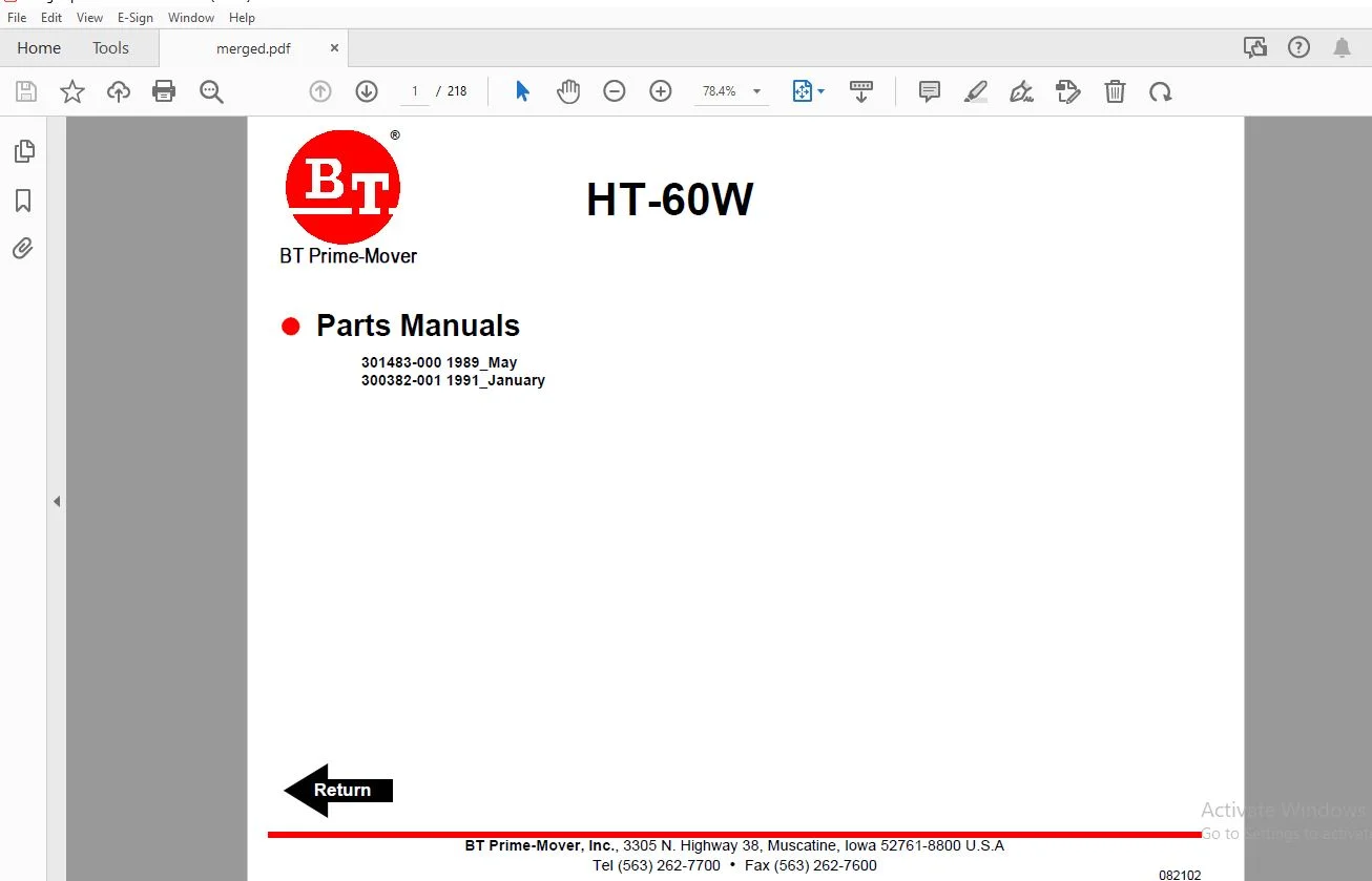
BT Prime-Mover HT-60W Parts Manuals – PDF DOWNLOAD
$27.95
BT Prime-Mover HT-60W Parts Manuals – PDF DOWNLOAD
301483-100 1989_May
300382-001 1991_January
Instant PDF Download
Available immediately
Save to Your Device
Download & keep forever
Antivirus Scanned
100% virus-free
Trusted Worldwide
175,000+ customers
Description
BT Prime-Mover HT-60W Parts Manuals – PDF DOWNLOAD
FILE DETAILS:
BT Prime-Mover HT-60W Parts Manuals – PDF DOWNLOAD
Language : English
Pages : 218
Downloadable : Yes
File Type : PDF
301483-100 1989_May
300382-001 1991_January
IMAGES PREVIEW OF THE MANUAL:
TABLE OF CONTENTS:
BT Prime-Mover HT-60W Parts Manuals – PDF DOWNLOAD
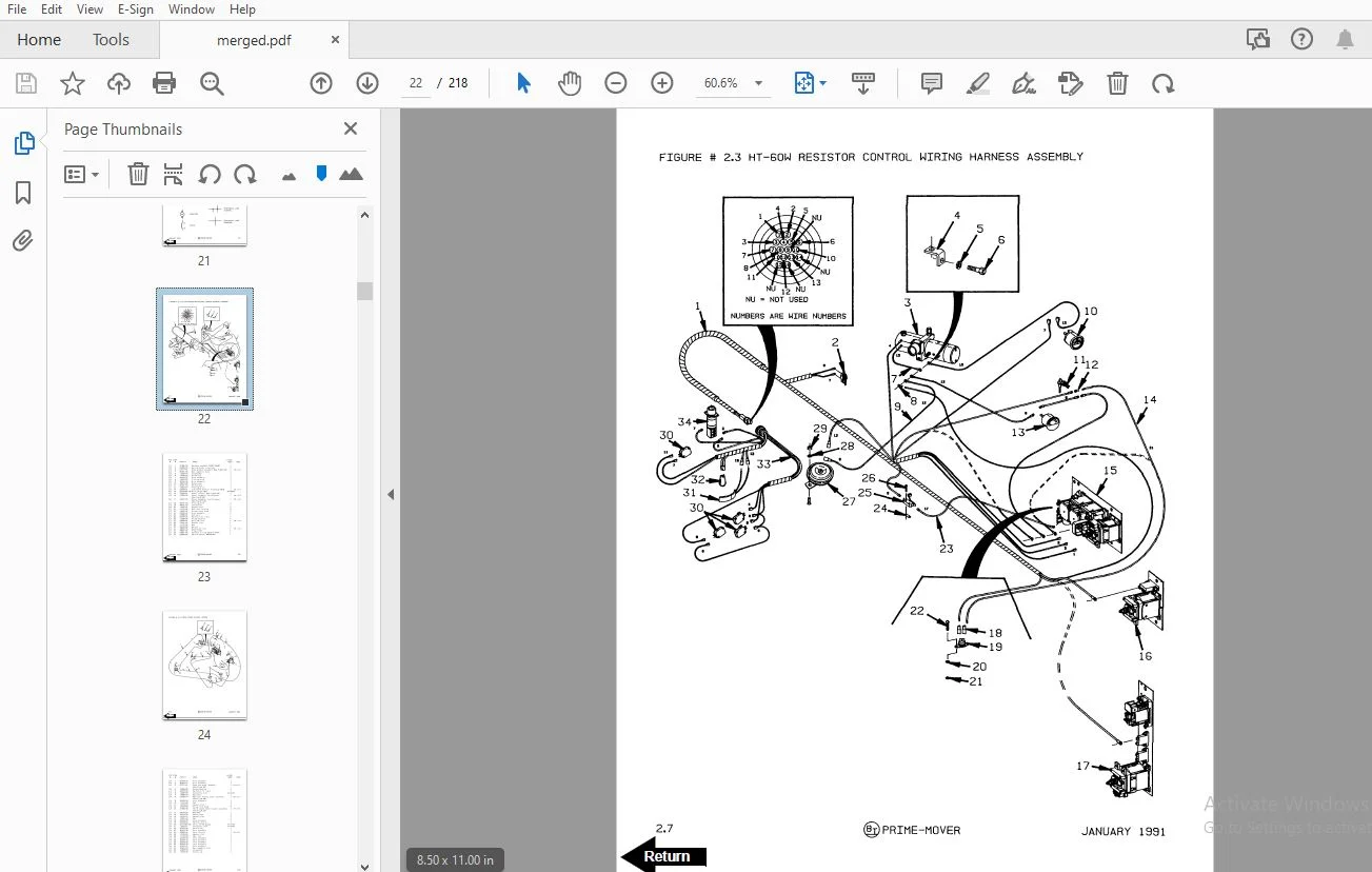
Front Cover...........................................................  2
Parts Ordering Instructions...........................................  4
General Information...................................................  5
Alphabetical Index....................................................  6
Figure # 0.1 Decals and Parts Assembly................................  8
Figure # 0.2 Parts List Index......................................... 10
Figure # 1.1 Transmission and Handle Assembly......................... 12
Figure # 1.2 HT-60W Resistor & Transistor Control Handle Assembly..... 14
Figure # 1.3 Part 1 14:1 Transmission Assembly........................ 16
Figure # 1.4 Part 2 14:1 Transmission Assembly........................ 18
Figure # 2.1 Resistor Electrical Schematic............................ 20
Figure # 2.2 Resistor Electrical Schematic Symbols.................... 21
Figure # 2.3 HT-60W Resistor Control Wiring Harness Assembly.......... 22
Figure # 2.4 Third Speed Control Wiring............................... 24
Figure # 2.5 Third Speed Power Component Wiring....................... 26
Figure # 2.6 Resistor Control Panel Assembly, 24 Volt................. 28
Figure # 2.7 Contactor Assembly, 24 Volt.............................. 30
Figure # 2.8 Forward & Rearward Contactor Assembly, 24 Volt........... 32
Figure # 2.9 Third Speed Contactor Panel Assembly..................... 34
Figure # 2.10 Fourth Speed Control Wiring............................. 36
Figure # 2.11 Fourth Speed Power Component Wiring..................... 38
Figure # 2.12 Fourth Speed Contactor Panel Assembly................... 40
Figure # 2.13 Contactor Assembly...................................... 42
Figure # 2.14 Resistor Power Connector Assembly....................... 44
Figure # 2.15 HT-60W Transistor Electrical Schematic.................. 46
Figure # 2.16 HT-60W Transistor Electrical Schematic Symbols.......... 47
Figure # 2.17 HT-60W Transistor Control Wiring Harness Assembly....... 48
Figure # 2.18 Transistor Power Component Wiring....................... 50
Figure # 2.19 HT-60W Control Panel Assembly, 24 Volt.................. 52
Figure # 2.20 Forward & Rearward Contactor Assembly, 24 Volt.......... 54
Figure # 2.21 1A Contactor Assembly................................... 56
Figure # 2.22 High Speed Contactor Assembly, 24 Volt.................. 58
Figure # 2.23 Transistor Power Connector Assembly..................... 60
Figure # 2.24 Hydraulic Pump Motor Assembly........................... 62
Figure # 2.25 Drive Motor Assembly.................................... 64
Figure # 3.1 Hydraulic Schematic...................................... 66
Figure # 3.2 Hydraulic Schematic Symbols.............................. 67
Figure # 3.3 Resistor Hydraulic System................................ 68
Figure # 3.4 Transistor Hydraulic System.............................. 70
Figure # 3.5 Pump and Motor Assembly.................................. 72
Figure # 3.6 Lift Cylinder Assembly................................... 74
Figure # 4.1 Shielding Assembly....................................... 76
Figure # 4.2 Carrier Frame Assembly................................... 78
Figure # 4.3 Caster Assembly.......................................... 80
Figure # 4.4 Lift Frame Assembly...................................... 82
Figure # 4.5 Pallet Entry Rollers..................................... 84
Figure # 4.6 Skid Adapter and Package Guard Assembly.................. 86
Figure # 4.7 Removable Load Backrest.................................. 88
Figure # 7.1 Special Tools and Lubrications........................... 90
Numerical Index....................................................... 93
Back Cover............................................................104
Front Cover...........................................................105
Parts Ordering Instructions...........................................108
Field Modifications...................................................108
General Information...................................................109
Alphabetical Index....................................................110
Figure # 0.1 Decals and Parts Assembly................................112
Figure # 0.2 Parts List and Service Reference Index...................114
Figure # 1.1 Transmission and Handle Assembly.........................116
Figure # 1.2 Handle Assembly..........................................118
Figure # 1.3 Part 1 14:1 Transmission Assembly........................120
Figure # 1.4 Part 2 14:1 Transmission Assembly........................122
Figure # 2.1 Resistor Master Control Switch...........................124
Figure # 2.2 EV-100/EV-1 SCR Master Control Switch....................126
Figure # 2.3 Resistor Electrical Schematic............................128
Figure # 2.4 Resistor Electrical Schematic Symbols....................129
Figure # 2.5 Resistor Control Wiring Harness Assembly.................130
Figure # 2.6 Third Speed Control Wiring...............................132
Figure # 2.7 Third Speed Power Component Wiring.......................134
Figure # 2.8 Resistor Control Panel Assembly..........................136
Figure # 2.9 Contactor Assembly.......................................138
Figure # 2.10 Forward & Rearward Contactor Assembly...................140
Figure # 2.11 Third Speed Contactor Panel Assembly....................142
Figure # 2.12 Fourth Speed Control Wiring.............................144
Figure # 2.13 Fourth Speed Power Component Wiring.....................146
Figure # 2.14 Fourth Speed Contactor Panel Assembly...................148
Figure # 2.15 Contactor Assembly......................................150
Figure # 2.16 EV-100 SCR Trucks Electrical Schematic..................152
Figure # 2.17 EV-100 SCR Truck Electrical Schematic Symbols...........153
Figure # 2.18 EV-100 SCR Control Wiring...............................154
Figure # 2.19 EV-100 SCR Third Speed Power Component Wiring...........156
Figure # 2.20 EV-100 SCR Contactor Panel Assembly.....................158
Figure # 2.21 EV-100 SCR Forward & Rearward Contactor Assembly........160
Figure # 2.22 EV-100 1A Contactor Assembly............................162
Figure # 2.23 EV-100 SCR Third Speed Pump Contactor Panel Assembly....164
Figure # 2.24 EV-100 SCR Fourth Speed Power Component Wiring..........166
Figure # 2.25 EV-100 SCR Fourth Speed Contactor Panel Assembly........168
Figure # 2.26 EV-100 SCR Third & Fourth Speed Control Panel...........170
Figure # 2.27 Power Connector Assembly................................172
Figure # 2.28 Hydraulic Pump Motor Assembly...........................174
Figure # 2.29 Drive Motor Assembly....................................176
Figure # 2.30 Wiring Assembly for Cold Storage........................178
Figure # 3.1 Hydraulic Schematic......................................180
Figure # 3.2 Hydraulic Schematic Symbols..............................181
Figure # 3.3 Hydraulic System.........................................182
Figure # 3.4 Pump and Motor Assembly..................................184
Figure # 3.5 Lift Cylinder Assembly...................................186
Figure # 4.1 Shielding Assembly.......................................188
Figure # 4.2 Carrier Frame Assembly...................................190
Figure # 4.3 Caster Assembly..........................................192
Figure # 4.4 Lift Frame Assembly......................................194
Figure # 4.5 Pallet Entry Rollers.....................................196
Figure # 4.6 Skid Adapter and Package Guard Assembly..................198
Figure # 4.7 Removable Load Backrest..................................200
Figure # 6.1 Special Tools and Lubrications...........................202
Numerical Index.......................................................205
Back Cover............................................................218
DESCRIPTION:
BT Prime-Mover HT-60W Parts Manuals – PDF DOWNLOAD
- When placing an order, always supply the part number and the serial number of your machine. Providing this information ensures prompt and efficient processing of your order. Note that the pictorial reference number is not required and including it may cause unnecessary confusion.
- Your dealer typically keeps many parts in stock and maintains up-to-date pricing for all items. This allows for immediate order processing. If a part is not in stock, the dealer will order it directly from the factory. Dealers also maintain a current file of service references, which include all available technical and parts ordering information.
- Please note that all prices are FOB (Free on Board) from the factory in Muscatine, Iowa. Shipping charges will be added to the price of any part shipped from the factory.
S.S 08/01/2025