BT Prime-Mover MX-50 RX-50 Electric Low Lift Pallet Truck Parts Manual PDF
$28.95
BT Prime-Mover MX-50 RX-50 Electric Low Lift Pallet Truck Parts Manual – PDF DOWNLOAD
Manual Number 9108
Manual Part Number 301443-000
Description
BT Prime-Mover MX-50 RX-50 Electric Low Lift Pallet Truck Parts Manual – PDF DOWNLOAD
FILE DETAILS:
BT Prime-Mover MX-50 RX-50 Electric Low Lift Pallet Truck Parts Manual – PDF DOWNLOAD
Language : English
Pages : 399
Downloadable : Yes
File Type : PDF
IMAGES PREVIEW OF THE MANUAL:
TABLE OF CONTENTS:
BT Prime-Mover MX-50 RX-50 Electric Low Lift Pallet Truck Parts Manual – PDF DOWNLOAD
Manual Number 9108
Manual Part Number 301443-000
Front Cover 2
Parts Ordering Instructions 3
General Information 4
Alphabetical Index 5
Figure # 0 1 Decals and Parts Assembly 7
Figure # 0 2 Parts List Index 9
Figure # 1 1 Transmission and Handle Assembly 11
Figure # 1 2 Twist Grip Resistor and Transistor Control Handle Assembly 13
Figure # 1 3 Thumb Control Resistor and Transistor Control Handle Assembly 15
Figure # 1 4 Transmission Assembly, Part # I 17
Figure # 1 5 Transmission Assembly # II 19
Figure # 1 6 Drive Motor Assembly 21
Figure # 2 1 Resistor Electrical Schematic 23
Figure # 2 2 Resistor Electrical Schematic Symbols 24
Figure # 2 3 Resistor Control Wiring Harness Assembly 25
Figure # 2 4 Resistor Third Speed Control Wiring 27
Figure # 2 5 Resistor Third Speed Power Component Wiring 29
Figure # 2 6 Resistor Control Panel Assembly 31
Figure # 2 7 Contactor Assembly 33
Figure # 2 8 Forward & Rearward Contactor Assembly 35
Figure # 2 9 Third Speed Contactor Panel Assembly 37
Figure # 2 10 Resistor Fourth Speed Control Wiring 39
Figure # 2 11 Resistor Fourth speed Power Component Wiring 41
Figure # 2 12 Fourth Speed Contactor Panel Assembly 43
Figure # 2 13 Contactor Assembly 45
Figure # 2 14 Resistor Power Connector Assembly 47
Figure # 2 15 MX-50 Transistor Electrical Schematic 49
Figure # 2 16 MX-50 Transistor Electrical Schematic Symbols 50
Figure # 2 17 RX-50 Transistor Electrical Schematic 51
Figure # 2 18 RX-50 Transistor Electrical Schematic Symbols 52
Figure # 2 19 Transistor Control Wiring Harness Assembly 53
Figure # 2 20 Transistor Power Component Wiring 55
Figure # 2 21 Control Panel Assembly, 24 Volt 57
Figure # 2 22 Forward & Rearward Contactor Assembly 59
Figure # 2 23 High Speed Contactor Assembly, 24 Volt 61
Figure # 2 24 Transistor Power Connector Assembly 63
Figure # 2 25 Hydraulic Pump Motor Assembly 65
Figure # 2 27 MX-50, 24 Volt Drive Motor Assembly 69
Figure # 2 28 RX-50, 12 Volt Drive Motor Assembly 71
Figure # 2 29 RX-50, 24 Volt Drive Motor Assembly 73
Figure # 3 1 Hydraulic Schematic 75
Figure # 3 2 Hydraulic Schematic Symbols 76
Figure # 3 3 Resistor Hydraulic System 77
Figure # 3 4 Transistor Hydraulic System 79
Figure # 3 5 Pump and Motor Assembly 81
Figure # 3 6 Lift Cylinder Assembly 83
Figure # 4 1 Shielding Assembly 85
Figure # 4 2 Carrier Frame Assembly 87
Figure # 4 3 Caster Assembly 89
Figure # 4 4 Lift Frame Assembly 91
Figure # 4 5 Pallet Entry Rollers 95
Figure # 4 6 Skid Adapter and Package Guard Assembly 97
Figure # 4 7 Removable Load Backrest 99
Figure # 5 1 Battery Pack 101
Figure # 5 2 Battery Pack Cable Assembly 103
Figure # 5 3 Battery Pack Connector Assembly 105
Figure # 7 1 Special Tools and Lubrications 107
Numerical Index 110
Back Cover 123
Front Cover 124
Parts Ordering Instructions 125
Field Mofications 125
General Information 126
Alphabetical Index 127
Figure # 0 1 Decals and Parts Assembly 129
Figure # 0 2 Parts List Index 131
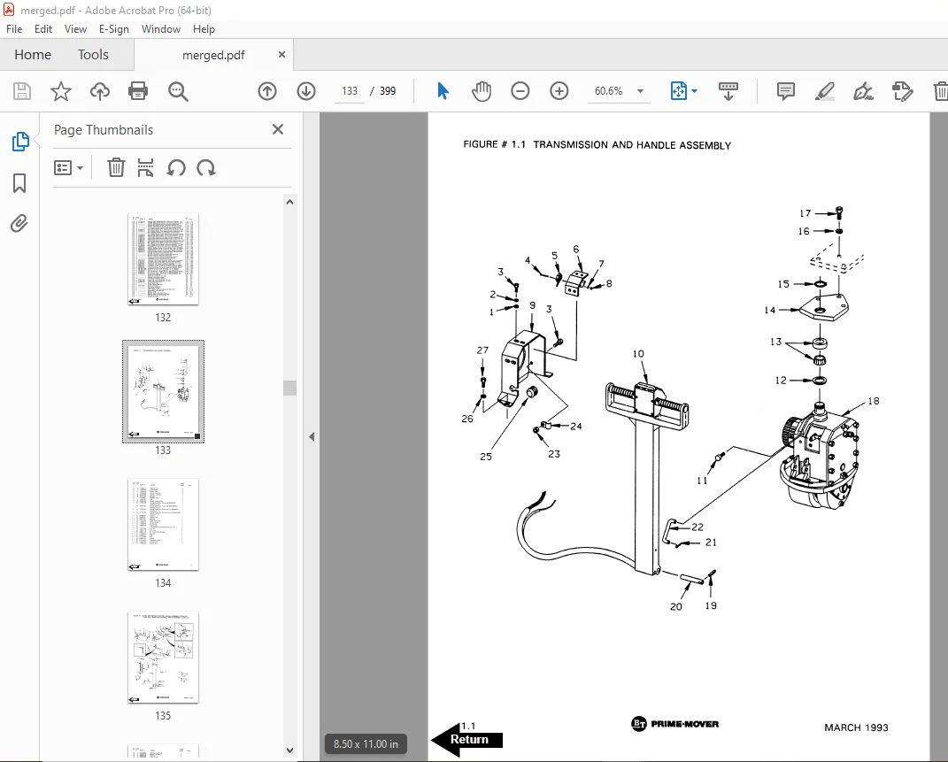
Figure # 1 1 Transmission and Handle Assembly 133
Figure # 1 2 Twist Grip Resistor/Transistor Control Handle Assembly 135
Figure # 1 3 Thumb Control Resistor/Transistor Control Handle Assembly 137
Figure # 1 4 Transmission Assembly Part # 1 139
Figure # 1 5 Transmission Assembly Part # 2 141
Figure # 1 6 Drive Motor Assembly 143
Figure # 2 1 MX/RX 2 & 3 Speed Resistor Electrical Schematic 145
Figure # 2 2 MX/RX 2 & 3 Speed Resistor Electrical Schematic Symbols 146
Figure # 2 3 MX/RX 2 & 3 Speed Resistor Control Wiring Harness Assembly 147
Figure # 2 4 MX/RX 2 & 3 Speed Resistor Control Wiring 149
Figure # 2 5 MX/RX 2 & 3 Speed Resistor Power Component Wiring 151
Figure # 2 6 MX/RX 2 Speed Resistor Control Panel Assembly 153
Figure # 2 7 MX/RX 2 & 3 Speed Second Speed Contactor Assembly 155
Figure # 2 8 MX/RX 2 & 3 Speed Forward & Rearward Contactor Assembly 157
Figure # 2 9 RX 3 Speed Third Speed Contactor Panel Assembly 159
Figure # 2 10 MX/RX 2 & 3 Speed Resistor Contactor Assembly 161
Figure # 2 11 MX/RX 3 Speed Walkie/4 Speed Rider Resistor Electrical Schematic 163
Figure # 2 12 Resistor Electrical Schematic Symbols 164
Figure # 2 13 MX 3 Speed Walkie Resistor Control Wiring Harness Assembly 165
Figure # 2 14 MX 3 Speed Walkie Resistor Third Speed Control Wiring 167
Figure # 2 15 MX 3 Speed Walkie Resistor Third Speed Power Component Wiring 169
Figure # 2 16 MX 3 Speed Walkie Third Speed Contactor Panel Assembly 171
Figure # 2 17 RX 4 Speed Resistor Fourth Speed Control Wiring 173
Figure # 2 18 RX 4 Speed Resistor Fourth Speed Power Component Wiring 175
Figure # 2 19 MX/RX 3 Speed Walkie/4 Speed Rider Resistor Control Panel Assembly 177
Figure # 2 20 MX/RX 3 & 4 Speed Second Speed Contactor Assembly 179
Figure # 2 21 MX/RX 3 & 4 Speed Forward & Rearward Contactor Assembly 181
Figure # 2 22 RX 4 Speed Fourth Speed Contactor Panel Assembly 183
Figure # 2 23 RX 4 Speed Fourth Speed Contactor Assembly 185
Figure # 2 24 MX/RX Resistor Power Connector Assembly 187
Figure # 2 25 MX-50 Transistor Electrical Schematic 189
Figure # 2 26 MX-50 Transistor Electrical Schematic Symbols 190
Figure # 2 27 RX-50 Transistor Electrical Schematic 191
Figure # 2 28 RX-50 Transistor Electrical Schematic Symbols 192
Figure # 2 29 Transistor Control Wiring Harness Assembly 193
Figure # 2 30 Transistor Power Component Wiring 195
Figure # 2 31 Transistor Control Panel Assembly, 24 Volt 197
Figure # 2 32 Forward & Rearward Contactor Assembly 199
Figure # 2 33 High Speed Contactor Assembly 201
Figure # 2 34 Transistor Power Connector Assembly 203
Figure # 2 35 Pump Motor Assembly 205
Figure # 2 36 MX/RX-50, 12 Volt Drive Motor Assembly 207
Figure # 2 37 MX-50, 24 Volt Drive Motor Assembly 209
Figure # 2 38 RX-50, 24 Volt Drive Motor Assembly 211
Figure # 3 1 Hydraulic Schematic 213
Figure # 3 2 Hydraulic Schematic Symbols 214
Figure # 3 3 Resistor Hydraulic System 215
Figure # 3 4 Transistor Hydraulic System 217
Figure # 3 5 Pump and Motor Assembly 219
Figure # 3 6 Lift Cylinder Assembly 221
Figure # 4 1 Shielding Assembly 223
Figure # 4 2 Carrier Frame Assembly 225
Figure # 4 3 Caster Assembly 227
Figure # 4 4 Lift Frame Assembly 229
Figure # 4 5 Pallet Entry Rollers 233
Figure # 4 6 Skid Adapter and Package Guard Assembly 235
Figure # 4 7 Removable Load Backrest 237
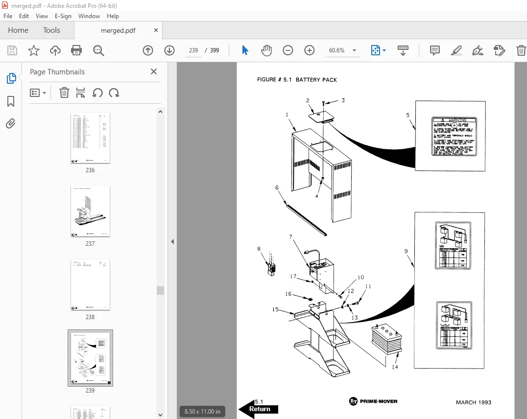
Figure # 5 1 Battery Pack 239
Figure # 5 2 Battery Pack Cable Assembly 241
Figure # 5 3 Battery Pack Connector Assembly 243
Figure # 10 1 Special Tools and Lubrications 245
Numerical Index 248
Back Cover 261
Front Cover 262
Parts Ordering Instructions 263
General Information 264
Alphabetical Index 265
Section 0 0 267
Figure # 0 1 267
Figure # 0 2 269
Section 1 0 271
Figure # 1 1 271
Figure # 1 2 273
Figure # 1 3 275
Figure # 1 4 277
Figure # 1 5 279
Figure # 1 6 281
Section 2 0 283
Figure # 2 1 283
Figure # 2 2 284
Figure # 2 3 285
Figure # 2 4 287
Figure # 2 5 289
Figure # 2 6 291
Figure # 2 7 293
Figure # 2 8 295
Figure # 2 9 297
Figure # 2 10 299
Figure # 2 11 301
Figure # 2 12 302
Figure # 2 13 303
Figure # 2 14 305
Figure # 2 15 307
Figure # 2 16 309
Figure # 2 17 311
Figure # 2 18 313
Figure # 2 19 315
Figure # 2 20 317
Figure # 2 21 319
Figure # 2 22 321
Figure # 2 23 323
Figure # 2 24 325
Figure # 2 25 327
Figure # 2 26 328
Figure # 2 27 329
Figure # 2 28 330
Figure # 2 29 331
Figure # 2 30 333
Figure # 2 31 335
Figure # 2 32 337
Figure # 2 33 339
Figure # 2 34 341
Figure # 2 35 343
Figure # 2 36 345
Figure # 2 37 347
Figure # 2 38 349
Section 3 0 351
Figure # 3 1 351
Figure # 3 2 352
Figure # 3 3 353
Figure # 3 4 355
Figure # 3 5 357
Figure # 3 6 359
Section 4 0 361
Figure # 4 1 361
Figure # 4 2 363
Figure # 4 3 365
Figure # 4 4 367
Figure # 4 5 371
Figure # 4 6 373
Figure # 4 7 375
Section 5 0 377
Figure # 5 1 377
Figure # 5 2 379
Figure # 5 3 381
Section 10 0 383
Figure # 10 1 383
Numerical Index 386
Back Cover 399
DESCRIPTION:
BT Prime-Mover MX-50 RX-50 Electric Low Lift Pallet Truck Parts Manual – PDF DOWNLOAD
Manual Number 9108
Manual Part Number 301443-000
PARTS ORDERING INSTRUCTIONS:
HOW TO ORDER:
- When you order, supply the part number, quantity, model and serial numbers of your machine. Supplying this information will assure prompt, efficient handling of your order. The pictorial reference number is not needed and including it can only add confusion.
- Since your dealer carries many parts in stock and maintains up-to-date prices on all parts, he will be able to process your order immediately. If, for some reason, the part is not in stock, he will order it from the factory. In either event, he maintains a current file of service manuals, which give all available parts ordering or technical information.
- All prices are FOB factory in Muscatine, Iowa. Shipping charges are added to the price of the part shipping from the factory.
WHERE TO ORDER:
Always order parts from the dealer who sold you your BT PRIME-MOVER. If it is necessary for the dealer to order parts from the factory, he is able to get prompt service for you. Parts are shipped in accordance with shipping instructions given on the order.
S.V 02/02/2025