BT Prime-Mover MX-65 RX-65 Electric Pallet Truck Parts Manual PDF
$28.95
BT Prime-Mover MX-65 RX-65 Electric Pallet Truck Parts Manual – PDF DOWNLOAD
Description
BT Prime-Mover MX-65 RX-65 Electric Pallet Truck Parts Manual – PDF DOWNLOAD
FILE DETAILS:
BT Prime-Mover MX-65 RX-65 Electric Pallet Truck Parts Manual – PDF DOWNLOAD
Language : English
Pages : 367
Downloadable : Yes
File Type : PDF
IMAGES PREVIEW OF THE MANUAL:
TABLE OF CONTENTS:
BT Prime-Mover MX-65 RX-65 Electric Pallet Truck Parts Manual – PDF DOWNLOAD
Front Cover 2
Parts Ordering Instructions 3
General Information 4
Alphabetical Index 5
Figure # 0 1 Decals and Parts Assembly 7
Figure # 0 2 Parts List Index 9
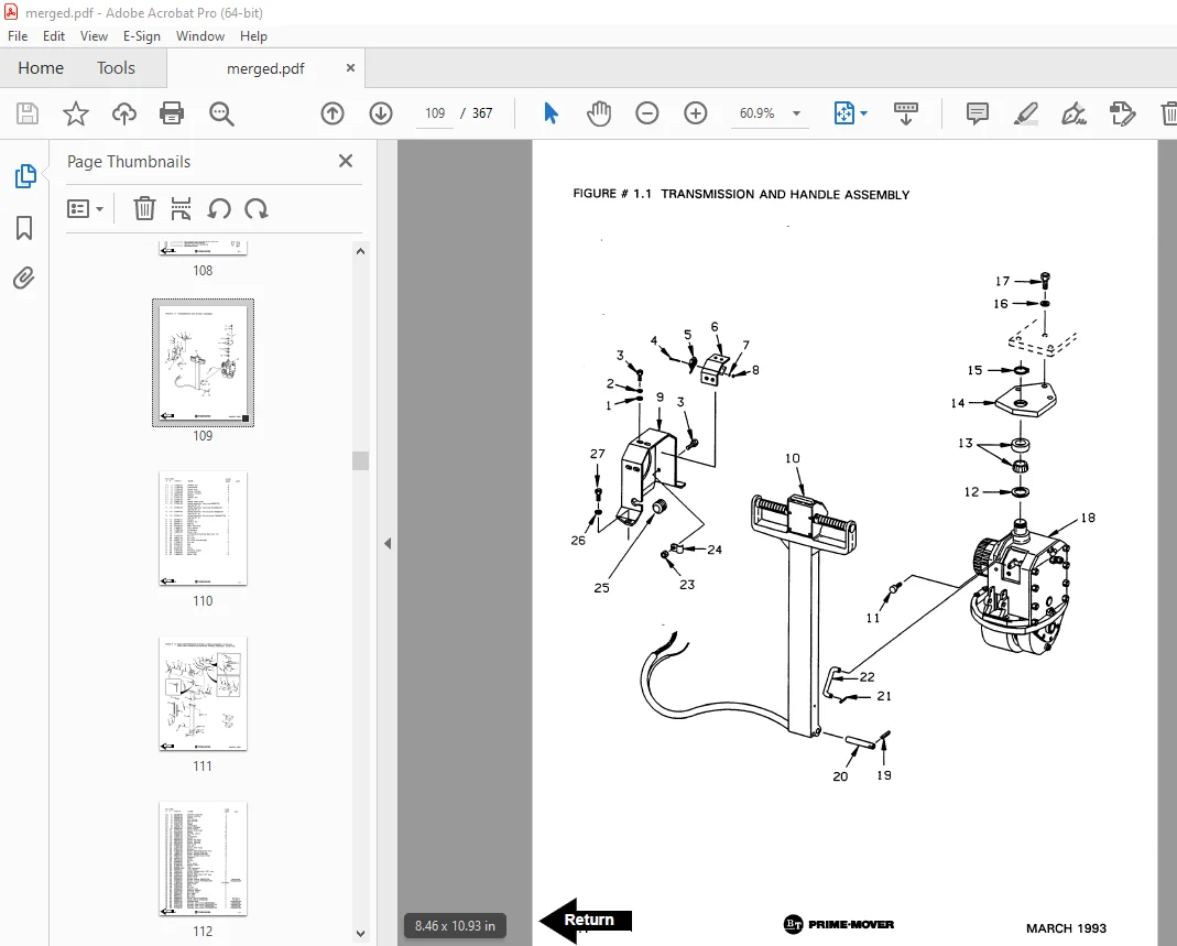
Figure # 1 1 Transmission and Handle Assembly 11
Figure # 1 2 Twist Grip Resistor and Transistor Control Handle Assembly 13
Figure # 1 3 Thumb Control Resistor and Transistor Control Handle Assembly 15
Figure # 1 4 Transmission Assembly, Part # I 17
Figure # 1 5 Transmission Assembly, Part # II 19
Figure # 1 6 Drive Motor Assembly 21
Figure # 2 1 Resistor Electrical Schematic 23
Figure # 2 2 Resistor Electrical Schematic Symbols 24
Figure # 2 3 Resistor Control Wiring Harness Assembly 25
Figure # 2 5 Resistor Third Speed Power Component Wiring 27
Figure # 2 6 Resistor Control Panel Assembly 29
Figure # 2 7 Contactor Assembly 31
Figure # 2 8 Forward and Rearward Contactor Assembly 33
Figure # 2 9 Third Speed Contactor Panel Assembly 35
Figure # 2 10 Resistor Fourth Speed Control Wiring 37
Figure # 2 11 Resistor Fourth Speed Power Component Wiring 39
Figure # 2 12 Fourth Speed Contactor Panel Assembly 41
Figure # 2 13 Contactor Assembly 43
Figure # 2 14 Resistor Power Connector Assembly 45
Figure # 2 15 MX-65 Transistor Electrical Schematic 47
Figure # 2 16 MX-65 Transistor Electrical Schematic Symbols 48
Figure # 2 17 RX-65 Transistor Electrical Schematic 49
Figure # 2 18 RX-65 Transistor Electrical Schematic Symbols 50
Figure # 2 19 Transistor Control Wiring Harness Assembly 51
Figure # 2 20 Transistor Power Component Wiring 53
Figure # 2 21 Control Panel Assembly, 24 Volt 55
Figure # 2 22 Forward & Rearward Contactor Assembly, 24 Volt 57
Figure # 2 23 High Speed Contactor Assembly, 24 Volt 59
Figure # 2 24 Transistor Power Connector Assembly 61
Figure # 2 25 Hydraulic Pump Motor Assembly 63
Figure # 2 26 MX-65, 12 Volt Drive Motor Assembly 65
Figure # 2 27 MX-65, 24 Volt Drive Motor Assembly 67
Figure # 2 28 RX-65, 12 Volt Drive Motor Assembly 69
Figure # 2 29 RX-65, 24 Volt Drive Motor Assembly 71
Figure # 3 1 Hydraulic Schematic 73
Figure # 3 2 Hydraulic Schematic Symbols 74
Figure # 3 3 Resistor Hydraulic System 75
Figure # 3 4 Transistor Hydraulic System 77
Figure # 3 5 Pump and Motor Assembly 79
Figure # 3 6 Lift Cylinder Assembly 81
Figure # 4 1 Shielding Assembly 83
Figure # 4 2 Carrier Frame Assembly 85
Figure # 4 3 Caster Assembly 87
Figure # 4 4 HX-65 Lift Frame Assembly 89
Figure # 4 5 Pallet Entry Rollers 91
Figure # 4 6 Skid Adapter and Package Guard Assembly 93
Figure # 4 7 Removable Load Backrest 95
Figure # 7 1 Special Tools and Lubrications 97
Back Cover 99
Front Cover 100
Parts Ordering Instructions 101
Field Modifications 101
General Information 102
Alphabetical Index 103
Figure # 0 1 Decals and Parts Assembly 105
Figure # 0 2 Parts List Index 107
Figure # 1 1 Transmission and Handle Assembly 109
Figure # 1 2 Twist Grip Resistor & Transistor Control Handle Assembly 111
Figure # 1 3 Thumb Control Resistor & Transistor Control Handle Assembly 113
Figure # 1 4 Transmission Assembly, Part # 1 115
Figure # 1 5 Transmission Assembly, Part # 2 117
Figure # 1 6 Drive Motor Assembly 119
Figure # 2 1 MX/RX 2 & 3 Speed Resistor Electrical Schematic 121
Figure # 2 2 MX/RX 2 & 3 Speed Resistor Electrical Schematic Symbols 122
Figure # 2 3 MX/RX 2 & 3 Speed Resistor Control Wiring Harness Assembly 123
Figure # 2 4 MX/RX 2 & 3 Speed Resistor Control Wiring 125
Figure # 2 5 MX/RX 2 & 3 Speed Resistor Power Component Wiring 127
Figure # 2 6 MX/RX 2 Speed Resistor Control Panel Assembly 129
Figure # 2 7 MX/RX 2 & 3 Speed Second Speed Contactor Assembly 131
Figure # 2 8 MX/RX 2 & 3 Speed Forward & Rearward Contactor Assembly 133
Figure # 2 9 RX 3 Speed Third Speed Contactor Panel Assembly 135
Figure # 2 10 MX/RX 2 & 3 Speed Resistor Contactor Assembly 137
Figure # 2 11 MX/RX 3 Speed Walkie/4 Speed Rider Resistor Electrical Schematic 139
Figure # 2 12 Resistor Electrical Schematic Symbols 140
Figure # 2 13 MX 3 Speed Walkie Resistor Control Wiring Harness Assembly 141
Figure # 2 14 MX 3 Speed Walkie Resistor Third Speed Control Wiring 143
Figure # 2 15 MX 3 Speed Walkie Resistor Third Speed Power Component Wiring 145
Figure # 2 16 MX 3 Speed Walkie Third Speed Contactor Panel Assembly 147
Figure # 2 17 RX 4 Speed Resistor Fourth Speed Control Wiring 149
Figure # 2 18 RX 4 Speed Resistor Fourth Speed Power Component Wiring 151
Figure # 2 19 MX/RX 3 Speed Walkie/4 Speed Rider Resistor Control Panel Assy 153
Figure # 2 20 MX/RX 3 & 4 Speed Second Speed Contactor Assembly 155
Figure # 2 21 MX/RX 3 & 4 Speed Forward & Rearward Contactor Assembly 157
Figure # 2 22 RX 4 Speed Fourth Speed Contactor Panel Assembly 159
Figure # 2 23 RX 4 Speed Fourth Speed Contactor Assembly 161
Figure # 2 24 MX/RX Resistor Power Connector Assembly 163
Figure # 2 25 MX-65 Transistor Electrical Schematic 165
Figure # 2 26 MX-65 Transistor Electrical Schematic Symbols 166
Figure # 2 27 RX-65 Transistor Electrical Schematic 167
Figure # 2 28 RX-65 Transistor Electrical Schematic Symbols 168
Figure # 2 29 Transistor Control Wiring Harness Assembly 169
Figure # 2 30 Transistor Power Component Wiring 171
Figure # 2 31 Transistor Control Panel Assembly, 24 Volt 173
Figure # 2 32 Forward & Rearward Contactor Assembly 175
Figure # 2 33 High Speed Contactor Assembly 177
Figure # 2 34 Transistor Power Connector Assembly 179
Figure # 2 35 Pump Motor Assembly 181
Figure # 2 36 MX/RX-65, 12 Volt Drive Motor Assembly 183
Figure # 2 37 MX-65, 24 Volt Drive Motor Assembly 185
Figure # 2 38 RX-65, 24 Volt Drive Motor Assembly 187
Figure # 3 1 Hydraulic Schematic 189
Figure # 3 2 Hydraulic Schematic Symbols 190
Figure # 3 3 Resistor Hydraulic System 191
Figure # 3 4 Transistor Hydraulic System 193
Figure # 3 5 Pump and Motor Assembly 195
Figure # 3 6 Lift Cylinder Assembly 197
Figure # 4 1 Shielding Assembly 199
Figure # 4 2 Carrier Frame Assembly 201
Figure # 4 3 Caster Assembly 203
Figure # 4 4 Lift Frame Assembly 205
Figure # 4 5 Pallet Entry Rollers 207
Figure # 4 6 Skid Adapter and Package Guard Assembly 209
Figure # 4 7 Removable Load Backrest 211
Figure # 10 1 Special Tools and Lubrications 213
Numerical Index 216
Back Cover 228
Front Cover 229
Pars Ordering Instructions 230
General Information 231
Alphabetical Index 232
Section 0 0 234
Figure # 0 1 234
Figure # 0 2 236
Section 1 0 238
Figure # 1 1 238
Figure # 1 2 240
Figure # 1 3 242
Figure # 1 4 244
Figure # 1 5 246
Figure # 1 6 248
Section 2 0 250
Figure # 2 1 250
Figure # 2 2 251
Figure # 2 3 252
Figure # 2 4 254
Figure # 2 5 256
Figure # 2 6 258
Figure # 2 7 260
Figure # 2 8 262
Figure # 2 9 264
Figure # 2 10 266
Figure # 2 11 268
Figure # 2 12 269
Figure # 2 13 270
Figure # 2 14 272
Figure # 2 15 274
Figure # 2 16 276
Figure # 2 17 278
Figure # 2 18 280
Figure # 2 19 282
Figure # 2 20 284
Figure # 2 21 286
Figure # 2 22 288
Figure # 2 23 290
Figure # 2 24 292
Figure # 2 25 294
Figure # 2 26 295
Figure # 2 27 296
Figure # 2 28 297
Figure # 2 29 298
Figure # 2 30 300
Figure # 2 31 302
Figure # 2 32 304
Figure # 2 33 306
Figure # 2 34 308
Figure # 2 35 310
Figure # 2 36 312
Figure # 2 37 314
Figure # 2 38 316
Section 3 0 318
Figure # 3 1 318
Figure # 3 2 319
Figure # 3 3 320
Figure # 3 4 322
Figure # 3 5 324
Figure # 3 6 326
Section 4 0 328
Figure # 4 1 328
Figure # 4 2 330
Figure # 4 3 332
Figure # 4 4 334
Figure # 4 5 336
Figure # 4 6 338
Figure # 4 7 340
Section 10 0 342
Figure # 10 1 342
Numerical Index 345
Back Cover 358
DESCRIPTION:
BT Prime-Mover MX-65 RX-65 Electric Pallet Truck Parts Manual – PDF DOWNLOAD
PARTS ORDERING INSTRUCTIONS:
HOW TO ORDER:
- When you order, supply the part number, quantity, model and serial numbers of your machine. Supplying this information will assure prompt, efficient handling of your order. The pictorial reference number is not needed and including it can only add confusion.
- Since your dealer carries many parts in stock and maintains up-to-date prices on all parts, he will be able to process your order immediately. If, for some reason, the part is not in stock, he will order it from the factory. In either event, he maintains a current file of service manuals, which give all available parts ordering or technical information.
- All prices are FOB factory in Muscatine, Iowa. Shipping charges are added to the price of the part shipping from the factory.
WHERE TO ORDER:
Always order parts from the dealer who sold you your BT PRIME-MOVER. If it is necessary for the dealer to order parts from the factory, he is able to get prompt service for you. Parts are shipped in accordance with shipping instructions given on the order.
S.V 02/02/2025