BT Prime Mover OE-35 Electric Order Selector Parts Manual 1991 PDF
$28.95
BT Prime Mover OE-35 Electric Order Selector Parts Manual 1991 – PDF DOWNLOAD
Description
BT Prime Mover OE-35 Electric Order Selector Parts Manual 1991 – PDF DOWNLOAD
FILE DETAILS:
BT Prime Mover OE-35 Electric Order Selector Parts Manual 1991 – PDF DOWNLOAD
Language : English
Pages : 178
Downloadable : Yes
File Type : PDF
IMAGES PREVIEW OF THE MANUAL:
TABLE OF CONTENTS:
BT Prime Mover OE-35 Electric Order Selector Parts Manual 1991 – PDF DOWNLOAD
A ___________________________________________________
ACC-10 and related parts installation 7.9 7.13
Antenna and related parts mounting installation 7.8 7.11
B ___________________________________________________
Brake cylinder assembly 3.4 3.5
Brake foot pedal installation 4.4 4.7
C ___________________________________________________
Control valve assembly 3.11 3.19
D ___________________________________________________
Decals and parts list assembly 0.1 0.1
Drive motor assembly, (24 Volt, G.E., 5BT1322B156) 2.18 2.33
Drive motor assembly, (36 Volt, Advanced, Y91-4002) 2.19 2.35
E ____________________________________________________
Emergency disconnect contactor assembly 2.14 2.25
EV-100 LX dash display installation 2.26 2.47
EV-100 LX contactor panel assembly & related parts for “E” and “EE” 2.8 2.13
EV-100 LX electrical schematic 2.1 2.1
EV-100 LX electrical schematic symbols 2.2 2.2
EV-100 LX power component wiring 2.6 2.9
EV-100 LX SCR 1A contactor assembly 2.11 2.19
EV-100 LX SCR contactor panel 2.9 2.15
EV-100 LX SCR control panel 2.7 2.11
EV-100 LX SCR forward & rearward contactor assembly 2.10 2.17
EV-100 LX SCR power steering contactor assembly 2.12 2.21
EV-100 LX TT electrical schematic 2.24 2.45
EV-100 LX TT electrical schematic symbols 2.25 2.46
F ___________________________________________________
Fan and related parts 6.2 6.3
Feedback potentiometer and tachometer installation 7.9 7.15
Fork mounting installation 4.5 4.9
Frame and load wheel installation 4.2 4.3
Frame steering control 4.12 4.23
Frame steering control and servo-motor installation 7.10 7.15
G,H _________________________________________________
Handle control assembly 4.7 4.13
Hydraulic schematic 3.1 3.1
Hydraulic schematic symbols 3.2 3.2
I,J,K,L _______________________________________________
Lift platform mast rollers and safty belt 4.9 4.17
Lift platform shielding assembly 4.8 4.15
Lift pump and motor assembly 3.9 3.15
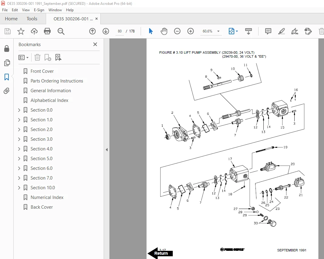
Lift pump assembly 3.10 3.17
Lift pump contactor assembly 2.13 2.23
Lift pump, control valve and related parts 3.8 3.13
M ___________________________________________________
Mast cable and related parts 2.4 2.5
Mast cable and related parts 7.6 7.7
Mast steering control part I 4.10 4.19
Mast steering control part II 4.11 4.21
ALPHABETICAL INDEX
SEPTEMBER 1991 5
NAME FIG.# PAGE #
N ___________________________________________________
N.D.C. Electrical schematic 24 VOLT 7.1 7.1
N.D.C. Electrical schematic 36 VOLT 7.3 7.3
N.D.C. Electrical schematic symbols 24 VOLT 7.2 7.2
N.D.C. Electrical schematic symbols 36 VOLT 7.4 7.4
N.D.C. Main frame wiring harness and relayed parts 7.7 7.9
N.D.C. Platform wiring harness and related parts 7.5 7.5
Numerical index * 99.1
O,P _________________________________________________
Pallet clamp installation 4.6 4.11
Parts list index 0.2 0.3
Platform hand rail installation 4.3 4.5
Power connector assembly, (GRAY) 2.15 2.27
Power connector assembly, (RED) 2.15 2.27
Power steering pump motor assy., (24 Volt, Leeson, C4D17DB1C) 2.20 2.37
Power steering pump motor assy., (36 volt, Ohio, B48-1228X7832) 2.21 2.39
Pump motor assembly, (Advanced, J90-4001) 2.16 2.29
Pump motor assembly, (P90-4001) 2.17 2.31
Q,R,S _______________________________________________
Shield assembly 4.1 4.1
Special tools and lubrications 10.1 10.1
Steering and brake hose assembly 3.3 3.3
Steering Pump and motor assembly 3.5 3.7
Steering Pump assembly 3.6 3.9
T ___________________________________________________
Three stage freelift cylinder assembly 3.16 3.29
Three stage mast freelift cylinder installation 5.8 5.15
Three stage mast hydraulic cylinder and related parts 3.14 3.25
Three stage mast inner column assembly 5.7 5.13
Three stage mast installation 5.4 5.7
Three stage mast intermediate column assembly 5.6 5.11
Three stage mast outer column assembly 5.5 5.9
Three stage staging cylinder assembly 3.15 3.27
Torque generator assembly 3.7 3.11
TQA control box installation 7.12 7.19
Transmission assembly, PART I 1.2 1.3
Transmission assembly, PART II 1.3 1.5
Transmission installation 1.1 1.1
Two stage mast hydraulic cylinder and related parts 3.12 3.21
Two stage mast inner column assembly 5.3 5.5
Two stage mast installation 5.4 5.7
Two stage outer column assembly 5.2 5.3
Two stage staging cylinder assembly 3.13 3.23
U,V,W ______________________________________________
Warning light assembly 2.22 2.41
Wiring assembly for cold storage 2.23 2.43
Wiring diagram part I frame 2.3 2.3
Wiring diagram part II platform 2.5 2.7
Working lights and related parts 6.1 6.1
X,Y,Z _______________________________________________
DESCRIPTION:
BT Prime Mover OE-35 Electric Order Selector Parts Manual 1991 – PDF DOWNLOAD
PARTS ORDERING INSTRUCTIONS:
HOW TO ORDER:
- When you order, supply the part number, quantity, model and serial numbers of your machine. Supplying this information will assure prompt, efficient handling of your order. The pictorial reference number is not needed and including it can only add confusion.
- Since your dealer carries many parts in stock and maintains up-to-date prices on all parts, he will be able to process your order immediately. If, for some reason, the part is not in stock, he will order it from the factory. In either event, he maintains a current file of service manuals, which give all available parts ordering or technical information.
- All prices are FOB factory in Muscatine, Iowa. Shipping charges are added to the price of the part shipping from the factory.
WHERE TO ORDER:
Always order parts from the dealer who sold you your BT PRIME-MOVER. If it is necessary for the dealer to order parts from the factory, he is able to get prompt service for you. Parts are shipped in accordance with shipping instructions given on the order.
S.V 10/01/2025