BT Prime Mover OE-35 Electric Order Selector Parts Manual OE35P8912 PDF
$34.95
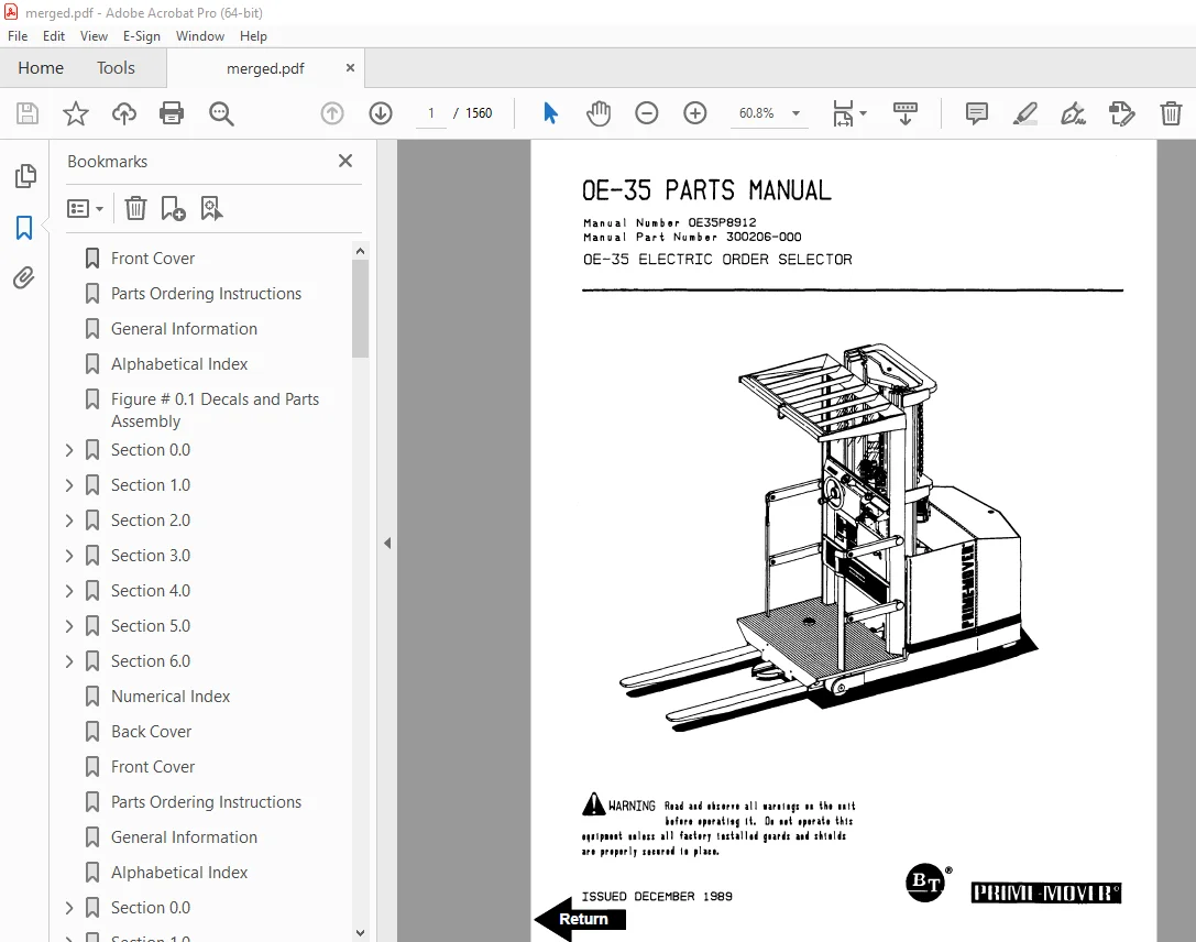
BT Prime Mover OE-35 Electric Order Selector Parts Manual OE35P8912 – PDF DOWNLOAD
Description
BT Prime Mover OE-35 Electric Order Selector Parts Manual OE35P8912 – PDF DOWNLOAD
FILE DETAILS:
BT Prime Mover OE-35 Electric Order Selector Parts Manual OE35P8912 – PDF DOWNLOAD
Language : English
Pages : 1560
Downloadable : Yes
File Type : PDF
IMAGES PREVIEW OF THE MANUAL:
TABLE OF CONTENTS:
BT Prime Mover OE-35 Electric Order Selector Parts Manual OE35P8912 – PDF DOWNLOAD
Front Cover 1
Parts Ordering Instructions 2
General Information 3
Alphabetical Index 4
Figure # 0 1 Decals and Parts Assembly 6
Section 0 0 6
Figure # 0 2 Parts List and Service Reference Index 8
Section 1 0 10
Figure # 1 1 Transmission Installation 10
Figure # 1 2 Part I 14:1 Transmission Assembly 12
Figure # 1 3 Part II 14:1 Transmission Assembly 14
Section 2 0 16
Figure # 2 1 EV-100 Electrical Schematic 16
Figure # 2 2 Electrical Schematic Symbols 17
Figure # 2 3 Wiring Diagram Part # I Frame 18
Figure # 2 4 Mast Cable and Related Parts 20
Figure # 2 5 Wiring Diagram Part # II Platform 22
Figure # 2 6 EV-100 Power Component Wiring 24
Figure # 2 7 EV-100 SCR Control Panel 26
Figure # 2 8 EV-100 SCR Contactor Panel Assembly 28
Figure # 2 9 EV-100 SCR Forward & Rearward Contactor Assembly 30
Figure # 2 10 EV-100 1A Contactor Assembly 32
Figure # 2 11 EV-100 Power Steering Contactor Assembly 34
Figure # 2 12 EV-100 Emergency Disconnect Contactor Assembly 36
Figure # 2 13 Power Connector Assembly 38
Figure # 2 14 Lift Motor Assembly 40
Figure # 2 15 Drive Motor Assembly 42
Figure # 2 16 Power Steering Pump Motor Assembly 44
Figure # 2 17 Warning Light Assembly 46
Figure # 2 18 Wiring Assembly for Cold Storage 48
Section 3 0 50
Figure # 3 1 Hydraulic Schematic 50
Figure # 3 2 Hydraulic Schematic Symbols 51
Figure # 3 3 Steering and Brake Hose Assembly 52
Figure # 3 4 Brake Cylinder Assembly 54
Figure # 3 5 Steering Pump and Motor Assembly 56
Figure # 3 6 Steering Pump Assembly 58
Figure # 3 7 Torque Generator Assembly 60
Figure # 3 8 Lift Pump, Control Valve and Related Parts 62
Figure # 3 9 Lift Pump and Motor Assembly 64
Figure # 3 10 Lift Pump Assembly 66
Figure # 3 11 Control Valve Assembly 68
Figure # 3 12 Two Stage Mast Hydraulic Cylinder and Related Parts 70
Figure # 3 13 Two Stage Staging Cylinder Assembly 72
Figure # 3 14 Three Stage Mast Hydraulic Cylinder and Related Parts 74
Figure # 3 15 Three Stage Staging Cylinder Assembly 76
Figure # 3 16 Three Stage Freelift Cylinder Assembly 78
Section 4 0 80
Figure # 4 1 Shielding Assembly 80
Figure # 4 2 Frame and Load Wheel Installation 82
Figure # 4 3 Platform Hand Rail Installation 84
Figure # 4 4 Brake Foot Pedal Installation 86
Figure # 4 5 Fork Mounting Installation 88
Figure # 4 6 Pallet Clamp Installation 90
Figure # 4 7 Handle Control Assembly 92
Figure # 4 8 Lift Platform Shielding Assembly 94
Figure # 4 9 Lift Platform Mast Rollers and Safety Belt 96
Figure # 4 10 Mast Steering Control Part # I 98
Figure # 4 11 Mast Steering Control Part # II 100
Figure # 4 12 Frame Steering Control 102
Section 5 0 104
Figure # 5 1 Two Stage Mast Installation 104
Figure # 5 2 Two Stage Outer Column Assembly 106
Figure # 5 3 Two Stage Inner Column Assembly 108
Figure # 5 4 Three Stage Mast Installation 110
Figure # 5 5 Three Stage Outer Column Assembly 112
Figure # 5 6 Three Stage Intermediate Column Assembly 114
Figure # 5 7 Three Stage Inner Column Assembly 116
Figure # 5 8 Three Stage Freelift Cylinder Installation 118
Section 6 0 120
Figure # 6 1 Special Tools and Lubrications 120
Numerical Index 123
Back Cover 138
Front Cover 139
Parts Ordering Instructions 140
General Information 141
Alphabetical Index 142
Section 0 0 144
Figure # 0 1 Decals and Parts Assembly 144
Figure # 0 2 Parts List Index 146
Section 1 0 148
Figure # 1 1 Transmission Installation 148
Figure # 1 2 Part I Transmission Assembly 150
Figure # 1 3 Part II Transmission Assembly 152
Section 2 0 154
Figure # 2 1 EV-100 LX Electrical Schematic 154
Figure # 2 2 EV-100 LX Electrical Schematic Symbols 155
Figure # 2 3 Wiring Diagram Part I Frame 156
Figure # 2 4 Mast Cable and Related Parts 158
Figure # 2 5 Wiring Diagram Part II Platform 160
Figure # 2 6 EV-100 LX Power Component Wiring 162
Figure # 2 7 EV-100 LX TX SCR Control Panel (49399-00) & EV-100 LX TT SCR Control Panel (49399-01) 164
Figure # 2 8 EV-100 LX Contactor Panel Assembly & Related Parts for “E” & “EE” 166
Figure # 2 9 EV-100 LX SCR Contactor Panel 168
Figure # 2 10 EV-100 LX SCR Forward & Rearward Contactor Assembly (27692-00) 170
Figure # 2 11 EV-100 LX SCR 1A Contactor Assembly (27693-02) 172
Figure # 2 12 EV-100 LX SCR Power Steering Contactor Assembly (300073-000) 174
Figure # 2 13 Lift Pump Contactor Assembly (24 Volt, 27693-02) (36 Volt, 202169) 176
Figure # 2 14 Emergency Disconnect Contactor Assembly (24 Volt, 300074-000) (36 Volt, 301265-000) 178
Figure # 2 15 Power Connector Assembly (Red, 49855-23) (Gray, 49855-20) 180
Figure # 2 16 24 Volt Pump Motor Assembly (J90-4001, 300282-000, Advanced) 182
Figure # 2 17 36 Volt Pump Motor Assembly (P90-4001, 300281-000, Advanced) 184
Figure # 2 18 24 Volt Drive Motor Assembly (27903-00, 5BT1322B156, G E ) 186
Figure # 2 19 36 Volt Drive Motor Assembly (29105-00, Y91-4002, Advanced) 188
Figure # 2 20 24 Volt Power Steering Pump Motor Assembly (200075, Leeson, C4D17DB1C) 190
Figure # 2 21 Power Steering Pump Motor Assembly (301492-000, 36 Volt) (B48-1228X7832) 192
Figure # 2 22 Warning Light Assembly 194
Figure # 2 23 Wiring Assembly for Cold Storage 196
Figure # 2 24 EV-100 LX TT Electrical Schematic 198
Figure # 2 25 EV-100 LX TT Electrical Schematic Symbols 199
Figure # 2 26 EV-100 LX Dash Display Installation 200
Section 3 0 202
Figure # 3 1 Hydraulic Schematic 202
Figure # 3 2 Hydraulic Schematic Symbols 203
Figure # 3 3 Steering and Brake Hose Assembly 204
Figure # 3 4 Brake Cylinder Assembly (26468-00) 206
Figure # 3 5 Steering Pump and Motor Assembly (24 Volt, 26915-00) (36 Volt, 29471-00) 208
Figure # 3 6 Steering Pump Assembly 210
Figure # 3 7 Torque Generator Assembly (40795-01) 212
Figure # 3 8 Lift Pump, Control Valve and Related Parts 214
Figure # 3 9 Lift Pump and Motor Assembly 216
Figure # 3 10 Lift Pump Assembly (29239-00, 24 Volt) (29470-00, 36 Volt & “EE”) 218
Figure # 3 11 Control Valve Assembly (29472-00) 220
Figure # 3 12 Two Stage Mast Hydraulic Cylinder and Related Parts 222
Figure # 3 13 Two Stage Staging Cylinder Assembly (29101-XX) 224
Figure # 3 14 Three Stage Mast Hydraulic Cylinder and Related Parts 226
Figure # 3 15 Three Stage Staging Cylinder Assembly (29101-XX) 228
Figure # 3 16 Three Stage Free Lift Cylinder Assembly (28150-XX) 230
Section 4 0 232
Figure # 4 1 Shielding Assembly 232
Figure # 4 2 Frame and Load Wheel Installation 234
Figure # 4 3 Platform Hand Rail Installation 236
Figure # 4 4 Brake Foot Pedal Installation 238
Figure # 4 5 Fork Mounting Installation 240
Figure # 4 6 Pallet Clamp Installation 242
Figure # 4 7 Handle Control Assembly 244
Figure # 4 8 Lift Platform Shielding Assembly 246
Figure # 4 9 Lift Platform Mast Rollers and Safety Belt 248
Figure # 4 10 Mast Steering Control Part # I 250
Figure # 4 11 Mast Steering Control Part # II 252
Figure # 4 12 Frame Steering Control 254
Section 5 0 256
Figure # 5 1 Two Stage Mast Installation 256
Figure # 5 2 Two Stage Mast Outer Column Assembly 258
Figure # 5 3 Two Stage Mast Inner Column Assembly 260
Figure # 5 4 Three Stage Mast Installation 262
Figure # 5 5 Three Stage Mast Outer Column Assembly 264
Figure # 5 6 Three Stage Mast Intermediate Column Assembly 266
Figure # 5 7 Three Stage Mast Inner Column Assembly 268
Figure # 5 8 Three Stage Mast Freelift Cylinder Installation 270
Section 6 0 272
Figure # 6 1 Work Lights and Related Parts 272
Figure # 6 2 Fan and Related Parts 274
Section 7 0 276
Figure # 7 1 24 Volt N D C Electrical Schematic 276
Figure # 7 2 24 Volt N D C Electrical Schematic Symbols 277
Figure # 7 3 36 Volt N D C Electrical Schematic 278
Figure # 7 4 36 Volt N D C Electrical Schematic Symbols 279
Figure # 7 5 N D C Platform Wiring Harness and Related Parts 280
Figure # 7 6 Mast Cable and Related Parts 282
Figure # 7 7 N D C Main Frame Wiring Harness and Related Parts 284
Figure # 7 8 Antenna and Related Parts Mounting Installation 286
Figure # 7 9 ACC-10 and Related Parts Installation 288
Figure # 7 10 Frame Steering Control and Servo-Motor Installation 290
Figure # 7 11 Feedback Potentiometer and Tachometer Installation 292
Figure # 7 12 TQA Control Box Installation 294
Section 10 0 296
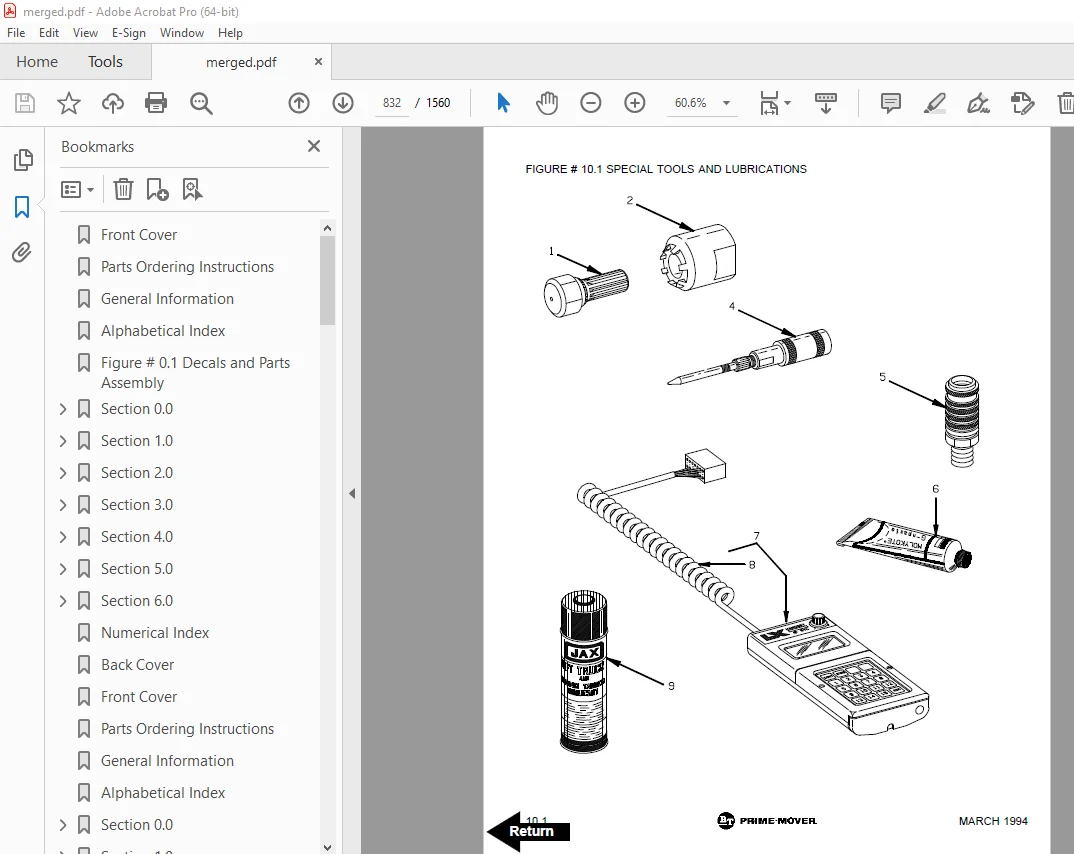
Figure # 10 1 Special Tools and Lubrications 296
Numerical Index 299
Back Cover 316
Front Cover 317
Parts Ordering Instructions 318
General Information 319
Alphabetical Index 320
Section # 0 0 322
Figure # 0 1 Decals and Parts Assembly 322
Figure # 0 2 Parts List Index 324
Section # 1 0 326
Figure # 1 1 Transmission Installation 326
Figure # 1 2 Part I Transmission Assembly 328
Figure # 1 3 Part II Transmission Assembly 330
Section # 2 0 332
Figure # 2 1 EV-100 LX Electrical Schematic 332
Figure # 2 2 EV-100 LX Electrical Schematic Symbols 333
Figure # 2 3 Wiring Diagram Part I Frame 334
Figure # 2 4 Mast Cable and Related Parts 336
Figure # 2 5 Wiring Diagram Part II Platform 338
Figure # 2 6 EV-100 LX Power Component Wiring 340
Figure # 2 7 EV-100 LX TX/TT SCR Control Panel 342
Figure # 2 8 EV-100 LX Contactor Panel Assembly & Related Parts for “E” & “EE” 344
Figure # 2 9 EV-100 LX SCR Contactor Panel 346
Figure # 2 10 EV-100 LX SCR Forward & Rearward Contactor Assembly 348
Figure # 2 11 EV-100 LX SCR 1A Contactor Assembly 350
Figure # 2 12 EV-100 LX SCR Power Steering Contactor Assembly 352
Figure # 2 13 Lift Pump Contactor Assembly 354
Figure # 2 14 Emergency Disconnect Contactor Assembly 356
Figure # 2 15 Power Connector Assembly 358
Figure # 2 16 24 Volt Pump Motor Assembly 360
Figure # 2 17 24 Volt Lift Pump Motor Assembly 362
Figure # 2 18 36 Volt Pump Motor Assembly 364
Figure # 2 19 24 Volt Drive Motor Assembly 366
Figure # 2 20 36 Volt Drive Motor Assembly 368
Figure # 2 21 24 Volt Power Steering Pump Motor Assembly 370
Figure # 2 22 Power Steering Pump Motor Assembly 372
Figure # 2 23 Warning Light Assembly 374
Figure # 2 24 Wiring Assembly for Cold Storage 376
Figure # 2 25 EV-100 LX TT Electrical Schematic 378
Figure # 2 26 EV-100 LX TT Electrical Schematic Symbols 379
Figure # 2 27 EV-100 LX Dash Display Installation 380
Figure # 2 28 Battery Lift Interrupt Installation 382
Section # 3 0 384
Figure # 3 1 Hydraulic Schematic 384
Figure # 3 2 Hydraulic Schematic Symbols 385
Figure # 3 3 Steering and Brake Hose Assembly 386
Figure # 3 4 Brake Cylinder Assembly 388
Figure # 3 5 Steering Pump and Motor Assembly 390
Figure # 3 6 Steering Pump Assembly 392
Figure # 3 7 Torque Generator Assembly 394
Figure # 3 8 Lift Pump, Control Valve and Related Parts 396
Figure # 3 9 Lift Pump and Motor Assembly 398
Figure # 3 10 Lift Pump Assembly 400
Figure # 3 11 Control Valve Assembly 402
Figure # 3 12 Two Stage Mast Hydraulic Cylinder and Related Parts 404
Figure # 3 13 Two Stage Staging Cylinder Assembly 406
Figure # 3 14 Three Stage Mast Hydraulic Cylinder and Related Parts 408
Figure # 3 15 Three Stage Staging Cylinder Assembly 410
Figure # 3 16 Three Stage Freelift Cylinder Assembly 412
Section # 4 0 414
Figure # 4 1 Shielding Assembly 414
Figure # 4 2 Frame and Load Wheel Installation 416
Figure # 4 3 Platform Hand Rail Installation 418
Figure # 4 4 Brake Foot Pedal Installation 420
Figure # 4 5 Fork Mounting Installation 422
Figure # 4 6 Pallet Clamp Installation 424
Figure # 4 7 Handle Control Assembly 426
Figure # 4 8 Lift Platform Shielding Assembly 428
Figure # 4 9 Lift Platform Mast Rollers and Safety Belt 430
Figure # 4 10 Mast Steering Control Part # I 432
Figure # 4 11 Mast Steering Control Part # II 434
Figure # 4 12 Frame Steering Control 436
Section # 5 0 438
Figure # 5 1 Two Stage Mast Installation 438
Figure # 5 2 Two Stage Mast Outer Column Assembly 440
Figure # 5 3 Two Stage Mast Inner Column Assembly 442
Figure # 5 4 Three Stage Mast Installation 444
Figure # 5 5 Three Stage Mast Outer Column Assembly 446
Figure # 5 6 Three Stage Mast Intermediate Column Assembly 448
Figure # 5 7 Three Stage Mast Inner Column Assembly 450
Figure # 5 8 Three Stage Mast Freelift Cylinder Installation 452
Section # 6 0 454
Figure # 6 1 Work Lights and Related Parts 454
Figure # 6 2 Fan and Related Parts 456
Section # 7 0 458
Figure # 7 1 24 Volt NDC Electrical Schematic 458
Figure # 7 2 24 Volt NDC Electrical Schematic Symbols 459
Figure # 7 3 36 Volt NDC Electrical Schematic 460
Figure # 7 4 36 Volt NDC Electrical Schematic Symbols 461
Figure # 7 5 NDC Platform Wiring Harness and Related Parts 462
Figure # 7 6 Mast Cable and Related Parts 464
Figure # 7 7 NDC Main Frame Wiring Harness and Related Parts 466
Figure # 7 8 Antenna and Related Parts Mounting Installation 468
Figure # 7 9 Micro 70 and Related Parts Installation 470
Figure # 7 10 Frame Steering Control and Servo-Motor Installation 472
Figure # 7 11 Feedback Potentiometer and Tachometer Installation 474
Figure # 7 12 36 Voltage Regulator Installation 476
Section # 10 0 478
Figure # 10 1 Special Tools and Lubrications 478
Numerical Index 481
Back Cover 500
Front Cover 501
Parts Ordering Instructions 502
General Information 503
Alphabetical Index 504
Section 0 0 506
Figure # 0 1 Decals and Parts Assembly 506
Section 1 0 508
Figure # 1 1 Transmission Installation 508
Figure # 1 2 Part 1 Transmission Assembly 510
Figure # 1 3 Part 2 Transmission Assembly 512
Section 2 0 514
Figure # 2 1 EV-100 LX Electrical Schematic 514
Figure # 2 2 EV-100 LX Electrical Schematic Symbols 515
Figure # 2 3 Wiring Diagram Part 1 Frame 516
Figure # 2 4 Mast Cable and Related Parts 518
Figure # 2 5 Wiring Diagram Part 2 Platform 520
Figure # 2 6 EV-100 LX Power Component Wiring 522
Figure # 2 7 EV-100 LX TX & TTSCR Control Panel 524
Figure # 2 8 EV-100 LX Contactor Panel Assembly & Related Parts for “E” & “EE” 526
Figure # 2 9 EV-100 LX SCR Contactor Panel 528
Figure # 2 10 EV-100 LX SCR Forward & Rearward Contactor Assembly 530
Figure # 2 11 EV-100 LX SCR 1A Contactor Assembly 532
Figure # 2 12 EV-100 LX SCR Power Steering Contactor Assembly 534
Figure # 2 13 Lift Pump Contactor Assembly 536
Figure # 2 14 Emergency Disconnect Contactor Assembly 538
Figure # 2 15 Power Connector Assembly 540
Figure # 2 16 24 Volt Pump Motor Assembly 542
Figure # 2 17 24 Volt Lift Pump Motor Assembly 544
Figure # 2 18 36 Volt Pump Motor Assembly 546
Figure # 2 19 24 Volt Drive Motor Assembly 548
Figure # 2 20 36 Volt Drive Motor Assembly 550
Figure # 2 21 24 Volt Power Steering Pump Motor Assembly 552
Figure # 2 22 Power Steering Pump Motor Assembly 554
Figure # 2 23 Warning Light Assembly 556
Figure # 2 24 Wiring Assembly for Cold Storage 558
Figure # 2 25 EV-100 LX TT Electrical Schematic 560
Figure # 2 26 EV-100 LX TT Electrical Schematic Symbols 561
Figure # 2 27 EV-100 LX Dash Display Installation 562
Figure # 2 28 Battery Lift Interrupt Installation 564
Section 3 0 566
Figure # 3 1 Hydraulic Schematic 566
Figure # 3 2 Hydraulic Schematic Symbols 567
Figure # 3 3 Steering and Brake Hose Assembly 568
Figure # 3 4 Brake Cylinder Assembly 570
Figure # 3 5 Steering Pump and Motor Assembly 572
Figure # 3 6 Steering Pump Assembly 574
Figure # 3 7 Lift Pump, Control Valve and Related Parts 576
Figure # 3 8 Lift Pump and Motor Assembly 578
Figure # 3 9 Lift Pump Assembly 580
Figure # 3 10 Control Valve Assembly 582
Figure # 3 11 Two Stage Mast Hydraulic Cylinder and Related Parts 584
Figure # 3 12 Two Stage Staging Cylinder Assembly 586
Figure # 3 13 Three Stage Clear View Mast Hydraulic Cylinders and Related Parts 588
Figure # 3 14 Three Stage Clear View Mast Staging Cylinder Assembly 590
Figure # 3 15 Three Stage Clear View Free Lift Cylinder Assembly 592
Section 4 0 594
Figure # 4 1 Shielding Assembly 594
Figure # 4 2 Frame and Load Wheel Installation 596
Figure # 4 3 Platform Hand Rail Installation 598
Figure # 4 4 Brake Foot Pedal and Chain Slack Switch Installation 600
Figure # 4 5 Fork Mounting Installation 602
Figure # 4 6 Pallet Clamp Installation 604
Figure # 4 7 Handle Control Assembly 606
Figure # 4 8 Lift Platform Shielding Assembly 608
Figure # 4 9 Lift Platform Mast Rollers and Safety Belt 610
Figure # 4 10 Mast Steering Control Part # 1 612
Figure # 4 11 Mast Steering Control Part # 2 614
Figure # 4 12 Frame Steering Control 616
Figure # 4 13 Caster Assembly 618
Section 5 0 621
Figure # 5 1 Two Stage Mast Installation 620
Figure # 5 2 Two Stage Mast Outer Column Assembly 622
Figure # 5 3 Two Stage Mast Inner Column Assembly 624
Figure # 5 4 Three Stage Clear View Mast Outer Column Assembly 626
Figure # 5 5 Three Stage Clear View Mast Intermediate Cylinder Assembly 628
Figure # 5 6 Three Stage Clear View Mast Inner Column Assembly 630
Figure # 5 7 Three Stage Clear View Mast Freelift Cylinder Installation 632
Section 6 0 634
Figure # 6 1 Lights and Fan Assembly 634
Section 7 0 636
Figure # 7 1 24 Volt NDC Electrical Schematic 636
Figure # 7 2 24 Volt NDC Electrical Schematic Symbols 637
Figure # 7 3 36 Volt NDC Electrical Schematic 638
Figure # 7 4 36 Volt NDC Electrical Schematic Symbols 639
Figure # 7 5 NDC Platform Wiring Harness and Related Parts 640
Figure # 7 6 Mast Cable and Related Parts 642
Figure # 7 7 NDC Main Frame Wiring Harness and Related Parts 644
Figure # 7 8 Antenna and Related Parts Mounting Installation 646
Figure # 7 9 Micro 70 and Related Parts Installation 648
Figure # 7 10 Frame Steering Control and Servo-Motor Installation 650
Figure # 7 11 Feedback Potentiometer and Tachometer Installation 652
Figure # 7 12 36 Voltage Regulator Installation 654
Section 10 0 656
Figure # 10 1 Special Tools and Lubrications 656
Numerical Index 659
Back Cover 676
Front Cover 677
Parts Ordering Instructions 678
General Information 679
Index 680
Section 0 0 682
Figure # 0 1 682
Section 1 0 684
Figure # 1 1 684
Figure # 1 2 686
Figure # 1 3 688
Section 2 0 690
Figure # 2 1 690
Figure # 2 2 691
Figure # 2 3 692
Figure # 2 4 694
Figure # 2 5 696
Figure # 2 6 698
Figure # 2 7 700
Figure # 2 8 702
Figure # 2 9 704
Figure # 2 10 706
Figure # 2 11 708
Figure # 2 12 710
Figure # 2 13 712
Figure # 2 14 714
Figure # 2 15 716
Figure # 2 16 718
Figure # 2 17 720
Figure # 2 18 722
Figure # 2 19 724
Figure # 2 20 726
Figure # 2 21 728
Figure # 2 22 730
Figure # 2 23 732
Figure # 2 24 734
Figure # 2 25 736
Figure # 2 26 737
Figure # 2 27 738
Figure # 2 28 740
Section 3 0 742
Figure # 3 1 742
Figure # 3 2 743
Figure # 3 3 744
Figure # 3 4 746
Figure # 3 5 748
Figure # 3 6 750
Figure # 3 7 752
Figure # 3 8 754
Figure # 3 9 756
Figure # 3 10 758
Figure # 3 11 760
Figure # 3 12 762
Figure # 3 13 764
Figure # 3 14 766
Figure # 3 15 768
Section 4 0 770
Figure # 4 1 770
Figure # 4 2 772
Figure # 4 3 774
Figure # 4 4 776
Figure # 4 5 778
Figure # 4 6 780
Figure # 4 7 782
Figure # 4 8 784
Figure # 4 9 786
Figure # 4 10 788
Figure # 4 11 790
Figure # 4 12 792
Figure # 4 13 794
Section 5 0 796
Figure # 5 1 796
Figure # 5 2 798
Figure # 5 3 800
Figure # 5 4 802
Figure # 5 5 804
Figure # 5 6 806
Figure # 5 7 808
Section 6 0 810
Figure # 6 1 810
Section 7 0 812
Figure # 7 1 812
Figure # 7 2 813
Figure # 7 3 814
Figure # 7 4 815
Figure # 7 5 816
Figure # 7 6 818
Figure # 7 7 820
Figure # 7 8 822
Figure # 7 9 824
Figure # 7 10 826
Figure # 7 11 828
Figure # 7 12 830
Section 10 0 832
Figure # 10 1 832
Numerical Index 835
Back Cover 852
Front Cover 853
Ordering Instructions 854
General Information 855
Alphabetical Index 856
Section 0 0 860
Figure # 0 1 860
Section 1 0 862
Figure # 1 1 862
Figure # 1 2 864
Figure # 1 3 866
Section 2 0 868
Figure # 2 1 868
Figure # 2 2 869
Figure # 2 3 870
Figure # 2 4 872
Figure # 2 5 874
Figure # 2 6 876
Figure # 2 7 878
Figure # 2 8 880
Figure # 2 9 882
Figure # 2 10 884
Figure # 2 11 886
Figure # 2 12 888
Figure # 2 13 890
Figure # 2 14 892
Figure # 2 15 894
Figure # 2 16 896
Figure # 2 17 898
Figure # 2 18 900
Figure # 2 19 902
Figure # 2 20 904
Figure # 2 21 906
Figure # 2 22 908
Figure # 2 23 910
Figure # 2 24 912
Figure # 2 25 914
Section 3 0 916
Figure # 3 1 916
Figure # 3 2 917
Figure # 3 3 918
Figure # 3 4 920
Figure # 3 5 922
Figure # 3 6 924
Figure # 3 7 926
Figure # 3 8 928
Figure # 3 9 930
Figure # 3 10 932
Figure # 3 11 934
Figure # 3 12 936
Figure # 3 13 938
Figure # 3 14 940
Figure # 3 15 942
Section 4 0 944
Figure # 4 1 944
Figure # 4 2 946
Figure # 4 3 948
Figure # 4 4 950
Figure # 4 5 952
Figure # 4 6 954
Figure # 4 7 956
Figure # 4 8 958
Figure # 4 9 960
Figure # 4 10 962
Figure # 4 11 964
Figure # 4 12 966
Figure # 4 13 968
Section 5 0 970
Figure # 5 1 970
Figure # 5 2 972
Figure # 5 3 974
Figure # 5 4 976
Figure # 5 5 978
Figure # 5 6 980
Figure # 5 7 982
Section 6 0 984
Figure # 6 1 984
Section 7 0 986
Figure # 7 1 986
Figure # 7 2 987
Figure # 7 3 988
Figure # 7 4 989
Figure # 7 5 990
Figure # 7 6 992
Figure # 7 7 994
Figure # 7 8 996
Figure # 7 9 998
Figure # 7 10 1000
Figure # 7 11 1002
Figure # 7 12 1004
Figure # 7 13 1006
Section 10 1 1008
Figure # 10 1 1008
Numerical Index 1011
Back Cover 1028
Front Cover 1029
Parts Ordering Instructions 1030
General Information 1031
Index 1032
Section 0 0 1036
Figure # 0 1 1036
Section 1 0 1038
Figure # 1 1 1038
Figure # 1 2 1040
Figure # 1 3 1042
Section 2 0 1044
Figure # 2 1 1044
Figure # 2 2 1045
Figure # 2 3 1046
Figure # 2 4 1048
Figure # 2 5 1050
Figure # 2 6 1052
Figure # 2 7 1054
Figure # 2 8 1056
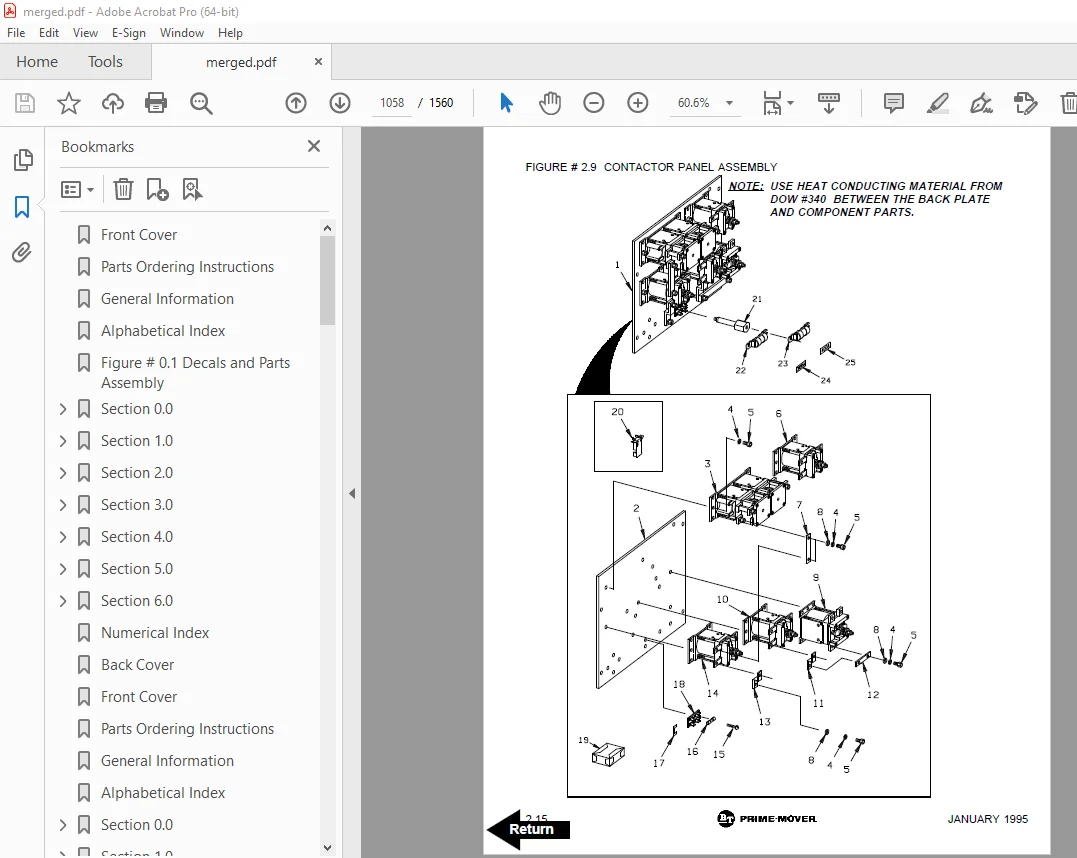
Figure # 2 9 1058
Figure # 2 10 1060
Figure # 2 11 1062
Figure # 2 12 1064
Figure # 2 13 1066
Figure # 2 14 1068
Figure # 2 15 1070
Figure # 2 16 1072
Figure # 2 17 1074
Figure # 2 18 1076
Figure # 2 19 1078
Figure # 2 20 1080
Figure # 2 21 1082
Figure # 2 22 1084
Figure # 2 23 1086
Figure # 2 24 1088
Figure # 2 25 1090
Section 3 0 1092
Figure # 3 1 1092
Figure # 3 2 1093
Figure # 3 3 1094
Figure # 3 4 1096
Figure # 3 5 1098
Figure # 3 6 1100
Figure # 3 7 1102
Figure # 3 8 1104
Figure # 3 9 1106
Figure # 3 10 1108
Figure # 3 11 1110
Figure # 3 12 1112
Figure # 3 13 1114
Figure # 3 14 1116
Figure # 3 15 1118
Figure # 3 16 1120
Section 4 0 1122
Figure # 4 1 1122
Figure # 4 2 1124
Figure # 4 3 1126
Figure # 4 4 1128
Figure # 4 5 1130
Figure # 4 6 1132
Figure # 4 7 1134
Figure # 4 8 1136
Figure # 4 9 1138
Figure # 4 10 1140
Figure # 4 11 1142
Figure # 4 12 1144
Figure # 4 13 1146
Section 5 0 1148
Figure # 5 1 1148
Figure # 5 2 1150
Figure # 5 3 1152
Figure # 5 4 1154
Figure # 5 5 1156
Figure # 5 6 1158
Figure # 5 7 1160
Figure # 5 8 1162
Section 6 0 1164
Figure # 6 1 1164
Section 7 0 1166
Figure # 7 1 1166
Figure # 7 2 1167
Figure # 7 3 1168
Figure # 7 4 1169
Figure # 7 5 1170
Figure # 7 6 1172
Figure # 7 7 1174
Figure # 7 8 1176
Figure # 7 9 1178
Figure # 7 10 1180
Figure # 7 11 1182
Figure # 7 12 1184
Figure # 7 13 1186
Numerical Index 1189
Back Cover 1206
Front Cover 1207
Parts Ordering Instructions 1208
General Information 1209
Index 1210
Section 0 0 1214
Figure # 0 1 1214
Section 1 0 1216
Figure # 1 1 1216
Figure # 1 2 1218
Figure # 1 3 1220
Section 2 0 1222
Figure # 2 1 1222
Figure # 2 2 1223
Figure # 2 3 1224
Figure # 2 4 1226
Figure # 2 5 1228
Figure # 2 6 1230
Figure # 2 7 1232
Figure # 2 8 1234
Figure # 2 9 1236
Figure # 2 10 1238
Figure # 2 11 1240
Figure # 2 12 1242
Figure # 2 13 1244
Figure # 2 14 1246
Figure # 2 15 1248
Figure # 2 16 1250
Figure # 2 17 1252
Figure # 2 18 1254
Figure # 2 19 1256
Figure # 2 20 1258
Figure # 2 21 1260
Figure # 2 22 1262
Figure # 2 23 1264
Figure # 2 24 1266
Figure # 2 25 1268
Section 3 0 1270
Figure # 3 1 1270
Figure # 3 2 1271
Figure # 3 3 1272
Figure # 3 4 1274
Figure # 3 5 1276
Figure # 3 6 1278
Figure # 3 7 1280
Figure # 3 8 1282
Figure # 3 9 1284
Figure # 3 10 1286
Figure # 3 11 1288
Figure # 3 12 1290
Figure # 3 13 1292
Figure # 3 14 1294
Figure # 3 15 1296
Figure # 3 16 1298
Section 4 0 1300
Figure # 4 1 1300
Figure # 4 2 1302
Figure # 4 3 1304
Figure # 4 4 1306
Figure # 4 5 1308
Figure # 4 6 1310
Figure # 4 7 1312
Figure # 4 8 1314
Figure # 4 9 1316
Figure # 4 10 1318
Figure # 4 11 1320
Figure # 4 12 1322
Figure # 4 13 1324
Section 5 0 1326
Figure # 5 1 1326
Figure # 5 2 1328
Figure # 5 3 1330
Figure # 5 4 1332
Figure # 5 5 1334
Figure # 5 6 1336
Figure # 5 7 1338
Figure # 5 8 1340
Section 6 0 1342
Figure # 6 1 1342
Section 7 0 1344
Figure # 7 1 1344
Figure # 7 2 1345
Figure # 7 3 1346
Figure # 7 4 1347
Figure # 7 5 1348
Figure # 7 6 1350
Figure # 7 7 1352
Figure # 7 8 1354
Figure # 7 9 1356
Figure # 7 10 1358
Figure # 7 11 1360
Figure # 7 12 1362
Figure # 7 13 1364
Numerical Index 1367
Back Cover 1388
Front Cover 1389
Parts Ordering Instructions 1390
General Information 1391
Alphabetical Index 1392
Section 0 0 1396
Figure # 0 1 1396
Section 1 0 1398
Figure # 1 1 1398
Figure # 1 2 1400
Figure # 1 3 1402
Section 2 0 1404
Figure # 2 1 1404
Figure # 2 2 1405
Figure # 2 3 1406
Figure # 2 4 1408
Figure # 2 5 1410
Figure # 2 6 1412
Figure # 2 7 1414
Figure # 2 8 1416
Figure # 2 9 1418
Figure # 2 10 1420
Figure # 2 11 1422
Figure # 2 12 1424
Figure # 2 13 1426
Figure # 2 14 1428
Figure # 2 15 1430
Figure # 2 16 1432
Figure # 2 17 1434
Figure # 2 18 1436
Figure # 2 19 1438
Figure # 2 20 1440
Figure # 2 21 1442
Figure # 2 22 1444
Section 3 0 1446
Figure # 3 1 1446
Figure # 3 2 1447
Figure # 3 3 1448
Figure # 3 4 1450
Figure # 3 5 1452
Figure # 3 6 1454
Figure # 3 7 1456
Figure # 3 8 1458
Figure # 3 9 1460
Figure # 3 10 1462
Figure # 3 11 1464
Figure # 3 12 1466
Figure # 3 13 1468
Figure # 3 14 1470
Figure # 3 15 1472
Figure # 3 16 1474
Section 4 0 1476
Figure # 4 1 1476
Figure # 4 2 1478
Figure # 4 3 1480
Figure # 4 4 1482
Figure # 4 5 1484
Figure # 4 6 1486
Figure # 4 7 1488
Figure # 4 8 1490
Figure # 4 9 1492
Figure # 4 10 1494
Figure # 4 11 1496
Figure # 4 12 1498
Figure # 4 13 1500
Section 5 0 1502
Figure # 5 1 1502
Figure # 5 2 1504
Figure # 5 3 1506
Figure # 5 4 1508
Figure # 5 5 1510
Figure # 5 6 1512
Figure # 5 7 1514
Figure # 5 8 1516
Section 6 0 1518
Figure # 6 1 1518
Section 7 0 1520
Figure # 7 1 1520
Figure # 7 2 1521
Figure # 7 3 1522
Figure # 7 4 1523
Figure # 7 5 1524
Figure # 7 6 1526
Figure # 7 7 1528
Figure # 7 8 1530
Figure # 7 9 1532
Figure # 7 10 1534
Figure # 7 11 1536
Figure # 7 12 1538
Section 10 1 1540
Figure # 10 1 1540
Numerical Index 1543
Back Cover 1560
DESCRIPTION:
BT Prime Mover OE-35 Electric Order Selector Parts Manual OE35P8912 – PDF DOWNLOAD
S.V 12/01/2025