BT Prime-Mover PE-60 Electric Walkie Low Lift Truck Parts Manual PDF
$28.95
BT Prime-Mover PE-60 Electric Walkie Low Lift Truck Parts Manual – PDF DOWNLOAD
PE40 Trucks
310519-000 1967_November
PE60 Trucks
300384-000 1989_May
301187-000 1990_October Parts Manual Update pages
300384-001 1991_April
PE80 Trucks
300389-000 1989_October
301191-000 1990_October Parts Manual Update pages
Description
BT Prime-Mover PE-60 Electric Walkie Low Lift Truck Parts Manual – PDF DOWNLOAD
FILE DETAILS:
BT Prime-Mover PE-60 Electric Walkie Low Lift Truck Parts Manual – PDF DOWNLOAD
Language : English
Pages : 373
Downloadable : Yes
File Type : PDF
IMAGES PREVIEW OF THE MANUAL:
TABLE OF CONTENTS:
BT Prime-Mover PE-60 Electric Walkie Low Lift Truck Parts Manual – PDF DOWNLOAD
PE40 Trucks
310519-000 1967_November
PE60 Trucks
300384-000 1989_May
301187-000 1990_October Parts Manual Update pages
300384-001 1991_April
PE80 Trucks
300389-000 1989_October
301191-000 1990_October Parts Manual Update pages
Front Cover 2
Parts Ordering Instructions 3
General Information 4
Alphabetical Index 5
Figure # 0 1 Decals and Parts Assembly 7
Figure # 0 2 Parts List and Service Reference Index 9
Figure # 1 1 Transmission and Handle Assembly 11
Figure # 1 2 Handle Assembly 13
Figure # 1 3 22:1 Part # I Transmission Assembly 15
Figure # 1 4 Single Disc Brake Transmissions Assembly 17
Figure # 1 5 Drive Motor Assembly 19
Figure # 2 1 Resistor Master Control Switch 21
Figure # 2 2 EV-100/EV-1 SCR Master Control Switch 23
Figure # 2 3 Resistor Electrical Schematic 25
Figure # 2 4 Resistor Electrical Schematic Symbols 26
Figure # 2 5 Resistor Control Wiring Harness Assembly 27
Figure # 2 6 Third Speed Power Component Wiring 29
Figure # 2 7 Resistor Control Panel Assembly 31
Figure # 2 8 Contactor Assembly 33
Figure # 2 9 Forward & Rearward Contactor Assembly 35
Figure # 2 10 Third Speed Contactor Panel Assembly 37
Figure # 2 11 EV-100 SCR Trucks Electrical Schematic 39
Figure # 2 12 EV-100 SCR Truck Electrical Schematic Symbols 40
Figure # 2 13 EV-100 SCR Control Wiring 41
Figure # 2 14 EV-100 SCR Power Component Wiring 43
Figure # 2 15 EV-100 SCR Contactor Panel Assembly 45
Figure # 2 16 EV-100 SCR Forward & Rearward Contactor Assembly 47
Figure # 2 17 EV-100 1A Contactor Assembly 49
Figure # 2 18 EV-100 SCR Pump Contactor Panel Assembly 51
Figure # 2 19 EV-100 SCR Control Panel 53
Figure # 2 20 Power Connector Assembly 55
Figure # 2 21 Hydraulic Pump Motor Assembly 57
Figure # 2 22 Drive Motor Assembly 59
Figure # 2 23 Wiring Assembly for Cold Storage 61
Figure # 3 1 Hydraulic Schematic 63
Figure # 3 2 Hydraulic Schematic Symbols 64
Figure # 3 3 Hydraulic System 65
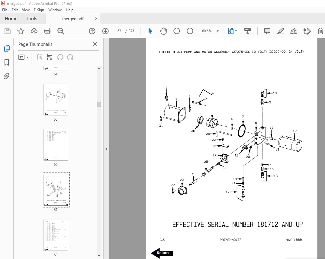
Figure # 3 4 Pump and Motor Assembly 67
Figure # 3 5 Lift Cylinder Assembly 69
Figure # 4 1 Shielding Assembly 71
Figure # 4 2 Carrier Frame Assembly 73
Figure # 4 3 Caster Assembly 75
Figure # 4 4 Lift Frame Assembly 77
Figure # 4 5 Pallet Entry Rollers 81
Figure # 4 6 Skid Adapter and Package Guard Assembly 83
Figure # 4 7 Removable Load Backrest 85
Figure # 6 1 Special Tools and Lubrications 87
Numerical Index 90
Back Cover 103
Front Cover 192
Parts Ordering Instructions 193
General Information 194
Alphabetical Index 195
Figure # 0 1 Decals and Parts Assembly 197
Figure # 0 2 Parts List and Service Reference Index 199
Figure # 1 1 Transmission and Handle Assembly 201
Figure # 1 2 Handle Assembly 203
Figure # 1 3 22:1 Part # 1 Transmission Assembly 205
Figure # 1 4 Part 2 22:1 Transmission Assembly 207
Figure # 1 5 Drive Motor Assembly 209
Figure # 2 1 Resistor Master Control Switch 211
Figure # 2 2 EV-100/EV-1 SCR Master Control Switch 213
Figure # 2 3 Resistor Electrical Schematic 215
Figure # 2 4 Resistor Electrical Schematic Symbols 216
Figure # 2 5 Resistor Control Wiring Harness Assembly 217
Figure # 2 6 Third Speed Power Component Wiring 219
Figure # 2 7 Resistor Control Panel Assembly 221
Figure # 2 8 Contactor Assembly 223
Figure # 2 9 Forward & Rearward Contactor Assembly 225
Figure # 2 10 Third Speed Contactor Panel Assembly 227
Figure # 2 11 EV-100 SCR Trucks Electrical Schematic 229
Figure # 2 12 EV-100 SCR Truck Electrical Schematic Symbols 230
Figure # 2 13 EV-100 SCR Control Wiring 231
Figure # 2 14 EV-100 SCR Power Component Wiring 233
Figure # 2 15 EV-100 SCR Contactor Panel Assembly 235
Figure # 2 16 EV-100 SCR Forward & Rearward Contactor Assembly 237
Figure # 2 17 EV-100 1A Contactor Assembly 239
Figure # 2 18 EV-100 SCR Pump Contactor Panel Assembly 241
Figure # 2 19 EV-100 SCR Control Panel 243
Figure # 2 20 Power Connector Assembly 245
Figure # 2 21 Hydraulic Pump Motor Assembly 247
Figure # 2 22 Drive Motor Assembly 249
Figure # 2 23 Wiring Assembly for Cold Storage 251
Figure # 3 1 Hydraulic Schematic 253
Figure # 3 2 Hydraulic Schematic Symbols 254
Figure # 3 3 Hydraulic System 255
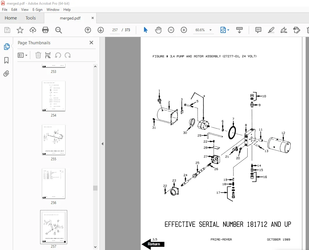
Figure # 3 4 Pump and Motor Assembly 257
Figure # 3 5 Lift Cylinder Assembly 259
Figure # 4 1 Shielding Assembly 261
Figure # 4 2 Carrier Frame Assembly 263
Figure # 4 3 Caster Assembly 265
Figure # 4 4 Lift Frame Assembly 267
Figure # 4 5 Pallet Entry Rollers 269
Figure # 4 6 Skid Adapter and Package Guard Assembly 271
Figure # 4 7 Removable Load Backrest 273
Figure # 6 1 Special Tools and Lubrications 275
Back Cover 277
Front Cover 312
Alphabetical Index 314
Figure # 1 6 PE-80 Resistor & Transistor Control Handle Assembly 315
Figure # 2 1 Resistor Master Control Switch 317
Figure # 2 24 PE-80 Transistor Electrical Schematic 319
Figure # 2 25 PE-80 Transistor Electrical Schematic Symbols 320
Figure # 2 26 PE-80 Transistor Control Wiring Harness Assembly 321
Figure # 2 27 PE-80 Transistor Power Component Wiring 323
Figure # 2 28 PE-80 Control Panel Assembly 325
Figure # 2 29 Forward & Rearward Contactor Assembly 327
Figure # 2 30 Power Connector Assembly 329
Figure # 3 1 Hydraulic Schematic 331
Figure # 3 2 Hydraulic Schematic Symbols 332
Figure # 3 3 Resistor Hydraulic System 333
Figure # 3 4 Pump and Motor Assembly 335
Figure # 3 6 Transistor Hydraulic System 337
Numerical Index 340
Back Cover 345
Front Cover 346
Prime-Mover Warranty 347
Contents 348
To New Prime-Mover Owners 348
Operating Instructions 349
Preliminary Service 349
Controls 349
Safety Interlock 349
Lift/Lower 349
Direction Control 349
Deadman Brake 349
Key Switch (Optional) 349
Horn (Optional) 350
Dynamic Brake (Optional) 350
Operator Maintenance 350
Battery Care 350
Maintenance Instructions 351
Battery 351
Power Wiring 351
Control Wiring 351
Control Switches (Handle) 352
Limit Switch Adjustment (Lift) 352
Mechanical Brake 352
Interlock Switch 353
Transmission Rollers 353
Contactor Points 354
Motor Commutator 354
Hydraulic System 354
Service Instructions 355
Parts Ordering Instructions 355
Parts List Index 356
Control Handle 357
Drive Motor and Transmission Mounting 358
Transmission Assembly 360
Carrier Frame 361
Lift Frame and Linkage 362
Electrical Control Panel 363
Control Terminal Release Solenoid 364
Hydraulic Piping Diagram 365
Hydraulic Cylinder Assembly 365
Hydraulic Pump Parts List 366
Brake Linkage and Interlock Switch 367
Control Wiring 368
Control Switch Installation 369
Service Guide 371
DESCRIPTION:
BT Prime-Mover PE-60 Electric Walkie Low Lift Truck Parts Manual – PDF DOWNLOAD
PE40 Trucks
310519-000 1967_November
PE60 Trucks
300384-000 1989_May
301187-000 1990_October Parts Manual Update pages
300384-001 1991_April
PE80 Trucks
300389-000 1989_October
301191-000 1990_October Parts Manual Update pages
PARTS ORDERING INSTRUCTIONS:
HOW TO ORDER:
- When you order, supply the part number, quantity, model and serial numbers of your machine. Supplying this information will assure prompt, efficient handling of your order. The pictorial reference number is not needed and including it can only add confusion.
- Since your dealer carries many parts in stock and maintains up-to-date prices on all parts, he will be able to process your order immediately. If, for some reason, the part is not in stock, he will order it from the factory. In either event, he maintains a current file of service manuals, which give all available parts ordering or technical information.
- All prices are FOB factory in Muscatine, Iowa. Shipping charges are added to the price of the part shipping from the factory.
WHERE TO ORDER:
Always order parts from the dealer who sold you your Prime-Mover. If it is necessary for the dealer to order parts from the factory, he is able to get prompt service for you. Parts are shipped in accordance with shipping instructions given on the order.
S.V 02/02/2025