BT Prime Mover PE-80 Electric Walkie Low Lift Truck Parts Manual PDF
$18.95
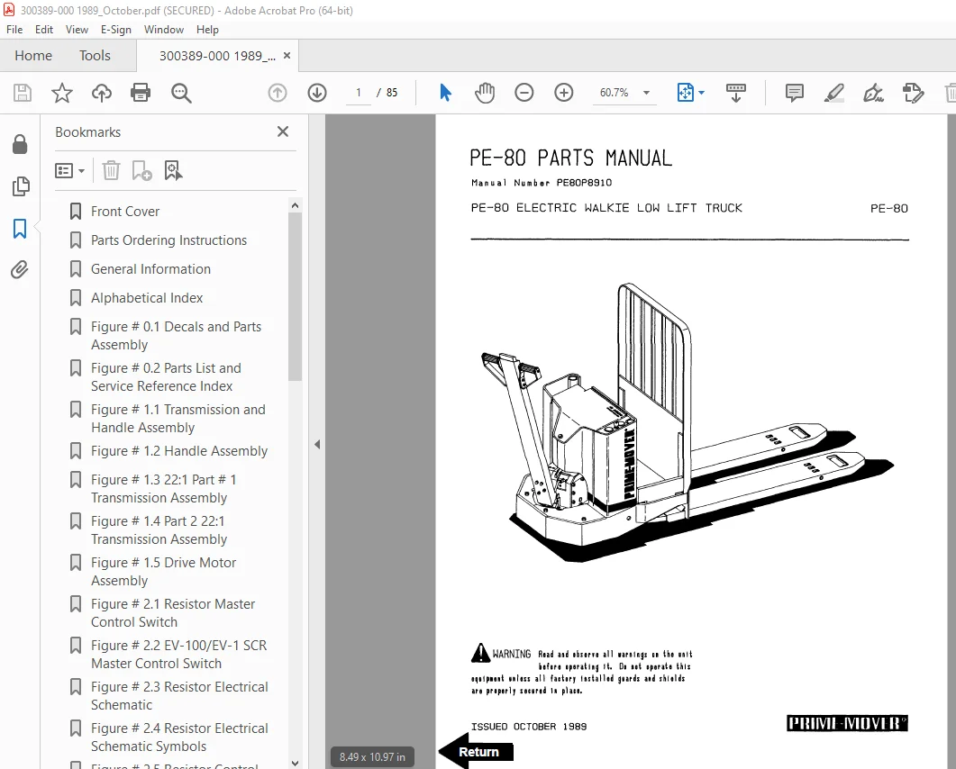
BT Prime Mover PE-80 Electric Walkie Low Lift Truck Parts Manual – PDF DOWNLOAD
Description
BT Prime Mover PE-80 Electric Walkie Low Lift Truck Parts Manual – PDF DOWNLOAD
FILE DETAILS:
BT Prime Mover PE-80 Electric Walkie Low Lift Truck Parts Manual – PDF DOWNLOAD
Language : English
Pages : 85
Downloadable : Yes
File Type : PDF
IMAGES PREVIEW OF THE MANUAL:
TABLE OF CONTENTS:
BT Prime Mover PE-80 Electric Walkie Low Lift Truck Parts Manual – PDF DOWNLOAD
Front Cover 1
Parts Ordering Instructions 2
General Information 3
Alphabetical Index 4
Figure # 0 1 Decals and Parts Assembly 6
Figure # 0 2 Parts List and Service Reference Index 8
Figure # 1 1 Transmission and Handle Assembly 10
Figure # 1 2 Handle Assembly 12
Figure # 1 3 22:1 Part # 1 Transmission Assembly 14
Figure # 1 4 Part 2 22:1 Transmission Assembly 16
Figure # 1 5 Drive Motor Assembly 18
Figure # 2 1 Resistor Master Control Switch 20
Figure # 2 2 EV-100/EV-1 SCR Master Control Switch 22
Figure # 2 3 Resistor Electrical Schematic 24
Figure # 2 4 Resistor Electrical Schematic Symbols 25
Figure # 2 5 Resistor Control Wiring Harness Assembly 26
Figure # 2 6 Third Speed Power Component Wiring 28
Figure # 2 7 Resistor Control Panel Assembly 30
Figure # 2 8 Contactor Assembly 32
Figure # 2 9 Forward & Rearward Contactor Assembly 34
Figure # 2 10 Third Speed Contactor Panel Assembly 36
Figure # 2 11 EV-100 SCR Trucks Electrical Schematic 38
Figure # 2 12 EV-100 SCR Truck Electrical Schematic Symbols 39
Figure # 2 13 EV-100 SCR Control Wiring 40
Figure # 2 14 EV-100 SCR Power Component Wiring 42
Figure # 2 15 EV-100 SCR Contactor Panel Assembly 44
Figure # 2 16 EV-100 SCR Forward & Rearward Contactor Assembly 46
Figure # 2 17 EV-100 1A Contactor Assembly 48
Figure # 2 18 EV-100 SCR Pump Contactor Panel Assembly 50
Figure # 2 19 EV-100 SCR Control Panel 52
Figure # 2 20 Power Connector Assembly 54
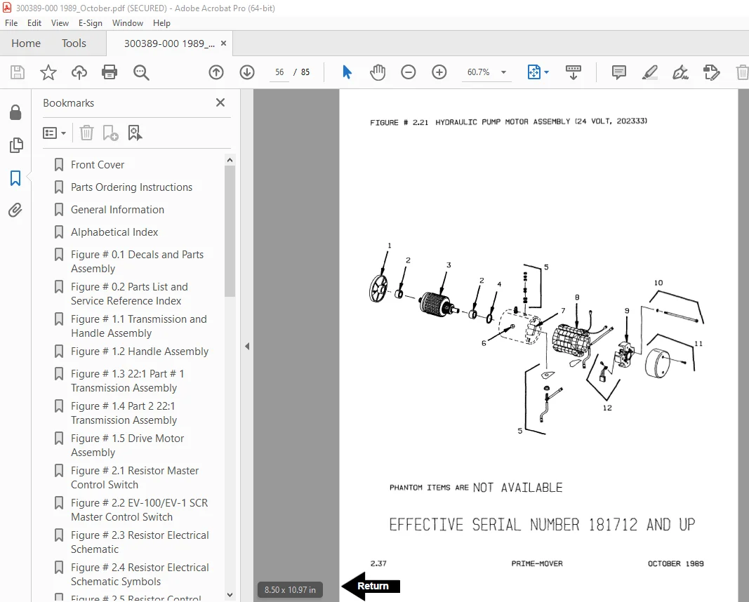
Figure # 2 21 Hydraulic Pump Motor Assembly 56
Figure # 2 22 Drive Motor Assembly 58
Figure # 2 23 Wiring Assembly for Cold Storage 60
Figure # 3 1 Hydraulic Schematic 62
Figure # 3 2 Hydraulic Schematic Symbols 63
Figure # 3 3 Hydraulic System 64
Figure # 3 4 Pump and Motor Assembly 66
Figure # 3 5 Lift Cylinder Assembly 68
Figure # 4 1 Shielding Assembly 70
Figure # 4 2 Carrier Frame Assembly 72
Figure # 4 3 Caster Assembly 74
Figure # 4 4 Lift Frame Assembly 76
Figure # 4 5 Pallet Entry Rollers 78
Figure # 4 6 Skid Adapter and Package Guard Assembly 80
Figure # 4 7 Removable Load Backrest 82
Figure # 6 1 Special Tools and Lubrications 84
S.V 20/01/2025