BT Prime-Mover PE/PL/HT Series Truck PE-45 PE-45R PE-45C PE-60 PE-60R PL-45 HT-45 HT-60 Parts Manual PDF
$27.95
BT Prime-Mover PE/PL/HT Series Truck PE-45 PE-45R PE-45C PE-60 PE-60R PL-45 HT-45 HT-60 Parts Manual – PDF DOWNLOAD
Description
BT Prime-Mover PE/PL/HT Series Truck PE-45 PE-45R PE-45C PE-60 PE-60R PL-45 HT-45 HT-60 Parts Manual – PDF DOWNLOAD
FILE DETAILS:
BT Prime-Mover PE/PL/HT Series Truck PE-45 PE-45R PE-45C PE-60 PE-60R PL-45 HT-45 HT-60 Parts Manual – PDF DOWNLOAD
Language : English
Pages : 122
Downloadable : Yes
File Type : PDF
IMAGES PREVIEW OF THE MANUAL:
TABLE OF CONTENTS:
BT Prime-Mover PE/PL/HT Series Truck PE-45 PE-45R PE-45C PE-60 PE-60R PL-45 HT-45 HT-60 Parts Manual – PDF DOWNLOAD
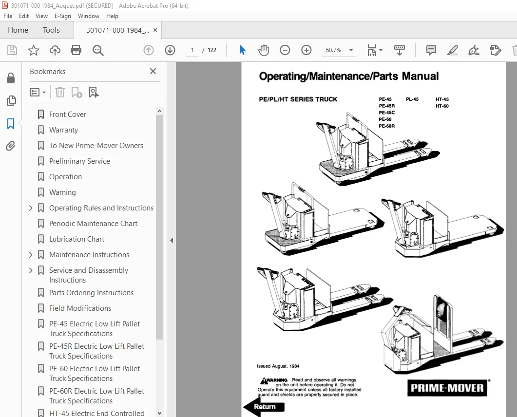
Front Cover 1
Warranty 2
To New Prime-Mover Owners 3
Preliminary Service 3
Operation 3
Warning 4
Operating Rules and Instructions 5
Operator Qualifications 5
Operator Training 5
Operator Responsibility 5
General Rules and Practices 5
Traveling 5
Loading 6
Operator Care of the Truck 6
Controls and Safety Equipment 7
Horn Switch 7
Raise Switch 7
Lower Switch 7
Third Speed Control Switch 7
Key Switch 7
Battery Discharge Indicator 7
Hourmeter 8
Safety Interlock Switch 8
Deadman Brake 8
Direction Control Handle 8
Direction Control 8
Resistor Control 8
SCR Control System 8
Periodic Maintenance Chart 9
Lubrication Chart 10
Maintenance Instructions 11
Battery 11
Theory of Electrical Operations 11
Control Switches 11
Power Wiring 11
Control Wiring 12
Lift Limit Switch 12
Mechanical Brake 12
Interlock Switch 13
Transmission Rollers 13
Contactor Points 13
Motor Commutator 13
60 Series Only Pull Rod Assembly/Adjustment 13
Hydraulic System 14
Hydraulic Pump/Motor 14
Hydraulic Filter 14
Pressure Relief Valve Adjustment 14
Service and Disassembly Instructions 15
Contactor Points 15
Flush Grease Fittings 15
Remove Handle and Transmission Assembly 15
Handle and Transmission Assembly 15
Disassembly 15
Assembly 16
Drive Wheel 16
Drive Motor 16
Assembly 16
Adjustment of Backlash for 22:1 Transmission 16
Gear Case Guide Ring 17
22:1 Transmission Assembly (Single Disc Brake Assembly) 17
Assembly of Drive Motor 17
22:1 Transmission Assembly (Multiple Disk Brake Assembly) 18
Assembly of Drive Motor 18
Mechanical Brake 19
Interlock Switch 20
Assembly of 14:1 Transmission 20
Directional Control Switch 22
Master Switch 22
Disassembly 22
Assembly 23
Electrical Panel Contactors 23
Disassembly 23
Assembly 23
Lift Frame 24
Hydraulic Pump 24
Release Valve and Solenoid 24
Hydraulic Cylinders 24
Contactor Assembly 24
Connections 24
Maintenance and Adjustment 24
Power Contacts 24
Disassembly 24
Inspection 25
Assembly 25
Parts Ordering Instructions 26
Field Modifications 26
PE-45 Electric Low Lift Pallet Truck Specifications 27
PE-45R Electric Low Lift Pallet Truck Specifications 28
PE-60 Electric Low Lift Pallet Truck Specifications 29
PE-60R Electric Low Lift Pallet Truck Specifications 30
HT-45 Electric End Controlled Low Lift Pallet Truck Specifications 31
HT-60 Electric End Controlled Low Lift Pallet Truck Specifications 32
Parts Information 33
Figure 1 Decal and Parts Assembly 33
Figure 2 Part List and Service Reference Index 34
Figure 3 Shield Assembly 36
Figure 4 PE45C Frame Components 37
Figure 5 PE45/60 Carrier Frame Assembly 38
Figure 6 PE45/60 22:1 Handle and Transmission Assembly 39
Figure 7 PE45C 22:1 Transmission and Handle Assembly 40
Figure 8 PE45/50 Handle Assembly 41
Figure 9 PE45C Handle Assembly 42
Figure 10 Master Control Switch Assembly 43
Figure 11 Master Control Switch Assembly 44
Figure 12 Master Control Switch Assembly 45
Figure 13 Master Control Switch Assembly 46
Figure 14 PE45/60 12 Volt 22:1 Transmission Assembly Part # 1 47
Figure 15 PE45/60 12 Volt 22:1 Transmission Assembly Part # 2 48
Figure 16 Drive Motor Assembly 49
Figure 17 12 Volt Drive Motor Assembly 50
Figure 18 24 Volt Drive Motor 51
Figure 19 PE45/60 24 Volt and PE45R/60R 12/24 Volt Multiple Disc Brake Transmission Assembly 52
Figure 20 Drive Motor Assembly 54
Figure 21 Drive Motor, 12 Volt 55
Figure 22 Drive Motor, 12 Volt 56
Figure 23 HT45/60 Transmission and Handle Assembly 57
Figure 24 HT45C 14:1 Transmission and Handle Assembly 58
Figure 25 HT45/80 14:1 Transmission Assembly with MEA-4023 Drive Motor 60
Figure 26 14:1 Motor Assembly 62
Figure 27 Spring Loaded Caster Assembly 63
Figure 28 Electrical Symbols 64
Figure 29 PE/PL Electrical Schematic 65
Figure 30 Control Wiring Harness Assembly 66
Figure 31 Riding Control Wiring Harness Assembly 67
Figure 32 PE/PL Power Component Assembly 68
Figure 33 Control Panel Assembly 69
Figure 34 G E Contactor Assembly 70
Figure 35 G E Contactor Assembly 71
Figure 36 3rd Speed Panel Assembly 72
Figure 37 Cableform 3rd Speed Panel Assembly 73
Figure 38 Contactor Assembly (Cableform) 74
Figure 39 HT45 & 60 Electrical Schematic 75
Figure 40 Control Wiring Harness Assembly 76
Figure 41 HT45/60 Riding Control Wiring 77
Figure 42 HT45/60 Power Component Assembly 78
Figure 43 HT45/60 Control Panel Assembly 79
Figure 44 3rd Speed Panel Assembly 80
Figure 45 G E Contactor Assembly 81
Figure 46 Dynamic Brake Control Wiring Assembly 82
Figure 47 Model 50 SCR, 24 Volt, Electrical Schematic 83
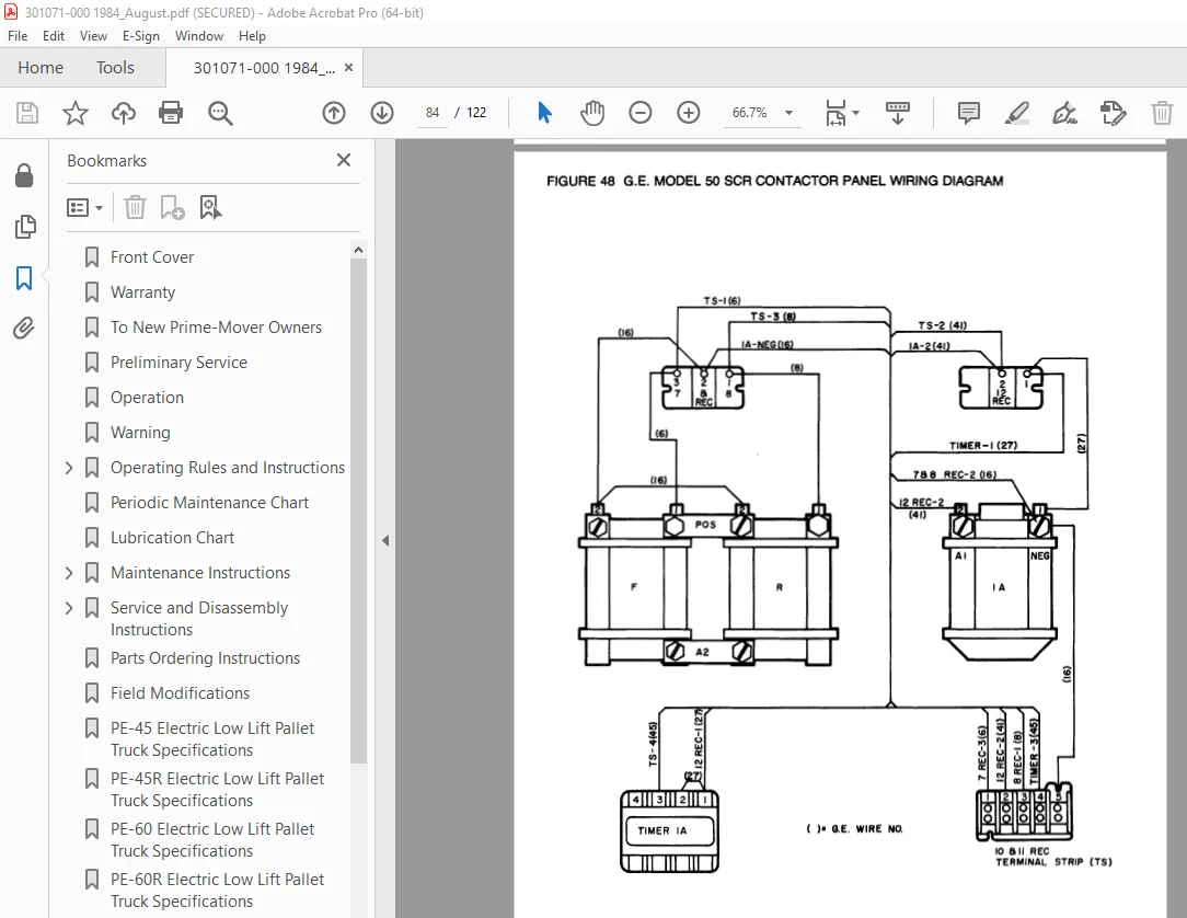
Figure 48 G E Model 50 SCR Contactor Panel Wiring Diagram 84
Figure 49 G E Model 50 SCR Panel Wiring Diagram 85
Figure 50 G E Model 50 SCR Control Wiring 86
Figure 51 Model 50 SCR Power Wiring (24 Volt) 87
Figure 52 Model 50 SCR Panel Assembly 88
Figure 53 Model SCR Contactor Panel 89
Figure 54 G E Model SCR Contactor – Forward/Reverse & 1A 90
Figure 55 Pump Cont Panel Assembly 91
Figure 56 EV-1 SCR Electrical Schematic 92
Figure 57 Model EV-1 Control Wiring Harness Assembly 93
Figure 58 EV-1 Power Component Assembly 94
Figure 59 EV-1 Contactor Panel Assembly 95
Figure 60 G E Contactor Assembly 96
Figure 61 G E Contactor Assembly 97
Figure 62 EV-1 Pump Contactor Panel 98
Figure 63 EV-1 SCR Control 99
Figure 64 Transformer Assembly 100
Figure 65 Rectifier Heat Sink Assembly 101
Figure 66 Power Connector Assembly 102
Figure 67 Hydraulic Schematic 103
Figure 68 Hydraulic Schematic Symbols 104
Figure 69 Hydraulic System 105
Figure 70 Hydraulic Pump and Motor Assembly 106
Figure 71 Motor Assembly 108
Figure 72 Cylinder Assembly 109
Figure 73 PE-45, PE-45C, PE-45R, HT-45 Lift Frame Assembly 110
Figure 74 PE-60, HT-60 Lift Frame Assembly 112
Figure 75 PL-45 Lift Frame Assembly 115
Figure 76 Foot Pedal Assembly 116
Figure 77 Pallet Entry Roller Assembly 117
Figure 78 PE/HT 45 & 60 Rider Platform 118
Figure 79 Skid Adapter and Package Guard Assembly 119
Figure 80 Removable Load Bucket Rest 120
Service Guide 121
DESCRIPTION:
BT Prime-Mover PE/PL/HT Series Truck PE-45 PE-45R PE-45C PE-60 PE-60R PL-45 HT-45 HT-60 Parts Manual – PDF DOWNLOAD
The Prime-Mover Electric Truck which you have just purchased was carefully designed and manufactured to ensure minimum cost, maximum reliability, and easy service. Extensive testing and high standards of quality control assure that these standards are maintained.
- To keep your Prime-Mover truck in good condition the periodic maintenance and lubrication guide should be followed.Prime-Mover trucks are also backed by a network of dealers who were chosen for their experience and reliability.
- They will assist you in keeping your Prime-Mover truck in peak operating condition.If you will take a moment to record the information it will be of help to you when parts and service assistance is needed.
OPERATION:
There are certain hazards that cannot be avoided solely by mechanical means in the everyday use of material handling trucks. Only the intelligence, good sense and care of the operator, along with proper maintenance will assure that the trucks are operated properly. It is important to have trained, reliable personnel operating your trucks.
- If at any time the operator finds that the truck is not performing properly, he should discontinue operation of the truck and report the condition to his supervisor for correction.Move and transport materials that have been properly and evenly loaded in as low a position as possible. Travel in a direction of maximumvisibility.
- The truck has been designed for level floor operation and should be operated in accordance with instructions in ANSI B56.1-1975. The operator should stay within the operators compartment with the safety chain hooked. If it is necessary to go outside the operator’scompartment when the operator platform is elevated, extreme caution should be exercised. It is recommended that a tether line and belt clamp be used in such cases.
- Operate the machine from the operator’s position after assuring that the operation will not endanger the operator or any other persons. Do not operate a truck in hazardous areas. Make sure that the forks and/or load have clearance to lower and do not “hang-up”.
S.V 21/01/2025