BT Prime Mover RC-30 RC-40 Electric Counterbalanced Rider Truck Parts Manual PDF
$28.95
BT Prime Mover RC-30 RC-40 Electric Counterbalanced Rider Truck Parts Manual – PDF DOWNLOAD
Manual Number RC30/4OP8909
Description
BT Prime Mover RC-30 RC-40 Electric Counterbalanced Rider Truck Parts Manual – PDF DOWNLOAD
FILE DETAILS:
BT Prime Mover RC-30 RC-40 Electric Counterbalanced Rider Truck Parts Manual – PDF DOWNLOAD
Language : English
Pages : 340
Downloadable : Yes
File Type : PDF
IMAGES PREVIEW OF THE MANUAL:
TABLE OF CONTENTS:
BT Prime Mover RC-30 RC-40 Electric Counterbalanced Rider Truck Parts Manual – PDF DOWNLOAD
Manual Number RC30/4OP8909
Front Cover 1
Parts Ordering Instructions 2
General Information 3
Alphabetical Index 4
Figure # 0 1 Decals and Parts Assembly 6
Figure # 0 2 Parts List and Service Reference Index 8
Figure # 1 1 Articulating Plate Assembly 10
Figure # 1 2 Steering Linkage 12
Figure # 1 3 Steering Assembly 14
Figure # 1 4 Power Steering Gear Box 16
Figure # 1 5 Forward Gear Reduction Steering Gear Box 18
Figure # 1 6 Reverse Chain Reduction Steering Gear Box 20
Figure # 1 7 Part 1 14:1 Transmission Assembly 22
Figure # 1 8 Part 2 14:1 Transmission Assembly 24
Figure # 1 9 Brake Linkage 26
Figure # 1 10 Slave Cylinder Assembly 28
Figure # 1 11 Master Cylinder Assembly 30
Figure # 1 12 Master Control Switch Handle Assembly 32
Figure # 2 1 EV-100/EV-1 SCR Master Control Switch 34
Figure # 2 2 EV-100 Electrical Schematic 36
Figure # 2 3 Electrical Schematic Symbols 37
Figure # 2 4 EV-100 Control Wiring 38
Figure # 2 5 EV-100 Power Component Wiring 40
Figure # 2 6 EV-100 SCR Contactor Panel Assembly 42
Figure # 2 7 EV-100 SCR Control Panel 44
Figure # 2 8 EV-100 SCR Forward & Rearward Contactor Assembly 46
Figure # 2 9 EV-100 1A Contactor Assembly 48
Figure # 2 10 EV-100 SCR Power Steering Contactor Assembly 50
Figure # 2 11 Power Connector Assembly 52
Figure # 2 12 Pump Motor Assembly 54
Figure # 2 13 Drive Motor Assembly 56
Figure # 2 14 Power Steering Motor Assembly 58
Figure # 2 15 Limit Switch Wiring Harness Assembly 60
Figure # 2 16 Warning Light Assembly 62
Figure # 2 17 Wiring Assembly for Cold Storage 64
Figure # 3 1 Hydraulic Schematic 66
Figure # 3 2 Hydraulic Schematic Symbols 67
Figure # 3 3 Lift Pump and Related Parts 68
Figure # 3 4 Two/Three Spool Control Valve Assembly 70
Figure # 3 5 24 Volt Lift Pump and Motor Assembly 72
Figure # 3 6 Lift Pump Assembly 74
Figure # 3 7 Two Stage Full Freelift Cylinders and Related Parts 76
Figure # 3 8 Cylinder Assembly 78
Figure # 3 9 Cylinder Assembly 80
Figure # 3 10 Two Stage Cylinder and Related Parts 82
Figure # 3 11 Two Stage Lift Cylinder Assembly 84
Figure # 3 12 Three Stage Cylinder and Related Parts 86
Figure # 3 13 Three Stage Staging Cylinder Assembly 88
Figure # 3 14 Three Stage Freelift Cylinder Assembly 90
Figure # 3 15 Tilt Cylinder and Related Parts 92
Figure # 3 16 Tilt Cylinder Assembly 94
Figure # 3 17 Two Stage Full Freelift Sideshifter Hydraulic Assembly 96
Figure # 3 18 Hose Reel and Related Parts 98
Figure # 3 19 Dual Elbow Swivel Assembly 100
Figure # 3 20 Gleason Hose Reel Assembly 102
Figure # 3 21 Power Steering Hydraulic Assembly 104
Figure # 3 22 Torque Generator Assembly 106
Figure # 3 23 Power Steering Pump and Motor Assembly 108
Figure # 3 24 Power Steering Pump Assembly 110
Figure # 3 25 Remote Lift/Lower Control Installation 112
Figure # 4 1 Shielding and Frame Assembly 114
Figure # 4 2 Control Valve Mounting Assembly 116
Figure # 4 3 Slide Link Installation 118
Figure # 4 4 Load Wheel Assembly 120
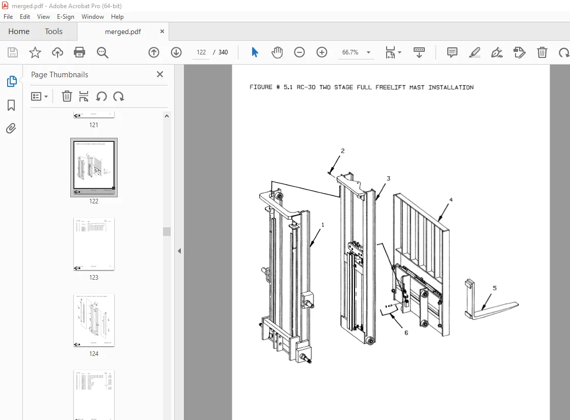
Figure # 5 1 RC-30 Two Stage Full Freelift Mast Installation 122
Figure # 5 2 RC-30 Two Stage Full Freelift Outer Column Assembly 124
Figure # 5 3 RC-30 Two Stage Full Lift Inner Column Assembly 126
Figure # 5 4 RC-30 Two Stage Freelift Cylinder Assembly and Related Parts 128
Figure # 5 5 RC-30 Two Stage Lift Frame and Load Backrest Assembly 130
Figure # 5 6 Sideshifter Assembly 132
Figure # 5 7 Fork Assembly 134
Figure # 5 8 Two Stage Mast Installation 136
Figure # 5 9 Two Stage Outer Column Assembly 138
Figure # 5 10 Two Stage Inner Column Assembly 140
Figure # 5 11 Two Stage Cylinder Assembly and Related Parts 142
Figure # 5 12 Two Stage Lift Frame and Load Backrest Assembly 144
Figure # 5 13 Three Stage Mast Installation 146
Figure # 5 14 Three Stage Outer Column Assembly 148
Figure # 5 15 Three Stage Intermediate Column Assembly 150
Figure # 5 16 Three Stage Inner Column Assembly 152
Figure # 5 17 Three Stage Freelift Cylinder Installation 154
Figure # 5 18 Three Stage Lift Frame and Load Backrest Assembly 156
Figure # 6 1 Special Tools and Lubrications 158
Front Cover 160
Parts Ordering Instructions 161
General Information 162
Alphabetical Index 163
Figure # 0 1 Decals and Parts Assembly 167
Figure # 0 2 Parts List Index 169
Figure # 1 1 Transmission and Drive Motor Installation 173
Figure # 1 2 Transmission Assembly, Part II 175
Figure # 2 1 EV-100/EV-1 SCR Master Control Switch (24455-01) 177
Figure # 2 2 EV-100 SCR Electrical Schematic 179
Figure # 2 3 EV-100 SCR Electrical Schematic Symbols 180
Figure # 2 4 EV-100 SCR Control Wiring 181
Figure # 2 5 EV-100 SCR Power Component Wiring 183
Figure # 2 6 EV-100 SCR Contactor Panel Assembly (28059-00) 185
Figure # 2 7 EV-100 SCR Control Panel (27691-01) 187
Figure # 2 8 EV-100LX SCR Forward & Rearward Contactor Assembly (27692-00) 189
Figure # 2 9 EV-100LX SCR Contactor Assembly (27693-02) 191
Figure # 2 10 EV-100LX SCR Power Steering Contactor Assembly (23015-01) 193
Figure # 2 11 Power Connector Assembly 195
Figure # 2 12 Lift Pump Motor Assembly (OHIO D-4608214XWF07, 300284-000) 197
Figure # 2 13 Drive Motor Assembly (G E 5BT1322, 27903-00) 199
Figure # 2 14 Power Steering Pump Motor Assembly (Prestolite MKG-4201, 204306) 201
Figure # 2 15 Limit Switch Wiring Harness Assembly 203
Figure # 2 16 Warning Light Assembly (29030-01, 24 Volt) 205
Figure # 2 17 Warning Light Assembly (29030-01, 24 Volt) 207
Figure # 3 1 Hydraulic Schematic 209
Figure # 3 2 Hydraulic Schematic Symbols 210
Figure # 3 3 Lift Pump and Related Parts 211
Figure # 3 4 Two Spool Control Valve Assembly (24924-00) & Three Spool Control Valve Assembly (24925-00) 213
Figure # 3 5 Lift Pump and Motor Assembly (300336-000) 215
Figure # 3 6 Lift Pump Assembly (200037) 217
Figure # 3 7 Two Stage Full Free Lift Cylinders and Related Parts 219
Figure # 3 8 Two Stage Full Free Lift Cylinders Assembly, 1-1/8 inch (24477-XX) 221
Figure # 3 9 Two Stage Full Free Lift Cylinders Assembly, 2-3/4 inch (24517-XX) 223
Figure # 3 10 Two Stage Cylinders and Related Parts 225
Figure # 3 11 Two Stage Lift Cylinder Assembly (RC-30 300744-XXX) (RC-40 300745-XXX) 227
Figure # 3 12 Three Stage Cylinder and Related Parts 229
Figure # 3 13 Three Stage Staging Cylinder Assembly (28131-XX) 231
Figure # 3 14 Three Stage Freelift Cylinder Assembly (28150-XX) 233
Figure # 3 15 Tilt Cylinder and Related Parts 235
Figure # 3 16 Tilt Cylinder Assembly (25635-XX) 237
Figure # 3 17 Two Stage Full Free Lift Sideshifter Hydraulic Assembly 239
Figure # 3 18 Hose Reel and Related Parts 241
Figure # 3 19 Dual Elbow Swivel Assembly (25623-00)\ 243
Figure # 3 20 Gleason Hose Reel Assembly 245
Figure # 3 21 Power Steering Hydraulic Assembly 247
Figure # 3 22 Torque Generator Assembly (26125-00) 249
Figure # 3 23 Power Steering Pump and Motor Assembly 251
Figure # 3 24 Power Steering Pump Assembly 253
Figure # 3 25 Remote Lift/Lower Control Installation 255
Figure # 4 1 Steering Linkage 257
Figure # 4 2 Articulating Plate Assembly and Related Parts 259
Figure # 4 3 Steering Assembly 261
Figure # 4 4 Power Steering Gear Box 263
Figure # 4 5 Forward Gear Reduction Steering Gear Box Assembly 265
Figure # 4 6 Reverse Chain Reduction Steering Gear Box Assembly 267
Figure # 4 7 Master Control Switch Handle Assembly 269
Figure # 4 8 Control Valve Mounting Assembly 271
Figure # 4 9 Slide Link Installation 273
Figure # 4 10 Load Wheel Assembly 275
Figure # 4 11 Brake Linkage 277
Figure # 4 12 Brake Slave Cylinder Assembly (25088-00) 279
Figure # 4 13 Brake Master Cylinder Assembly (25083-00) 281
Figure # 4 14 Shielding and Frame Assembly 283
Figure # 5 1 RC-30 Two Stage Full Freelift Mast Installation 285
Figure # 5 2 RC-30 Two Stage Full Freelift Outer Column Assembly 287
Figure # 5 3 RC-30 Two Stage Full Freelift Inner Column Assembly 289
Figure # 5 4 RC-30 Two Stage Full Freelift Cylinder Assembly and Related Parts 291
Figure # 5 5 RC-30 Two Stage Full Freelift Lift Frame and Load Backrest Assembly 293
Figure # 5 6 Sideshifter Assembly (25411-00) 295
Figure # 5 7 Fork Assembly (25008-XX) 297
Figure # 5 8 Two Stage Mast Installation 299
Figure # 5 9 Two Stage Outer Column Assembly 301
Figure # 5 10 Two Stage Inner Column Assembly 303
Figure # 5 11 Two Stage Cylinder Assembly and Related Parts 305
Figure # 5 12 Two Stage Lift Frame and Load Backrest Assembly 307
Figure # 5 13 Three Stage Mast Installation 309
Figure # 5 14 Three Stage Outer Column Assembly 311
Figure # 5 15 Three Stage Intermediate Column Assembly 313
Figure # 5 16 Three Stage Inner Column Assembly 315
Figure # 5 17 Three Stage Freelift Cylinder Installation 317
Figure # 5 18 Three Stage Lift Frame and Load Backrest Assembly 319
Figure # 7 1 Battery Lift Interrupt “E” EV-100LX SCR Electrical Schematic 321
Figure # 7 2 Battery Lift Interrupt “E” EV-100LX SCR Electrical Schematic Symbols 322
Figure # 7 3 Battery Lift Interrupt “EE” EV-100LX SCR Electrical Schematic 323
Figure # 7 4 Battery Lift Interrupt “EE” EV-100LX SCR Electrical Schematic Symbols 324
Figure # 7 5 Battery Lift Interrupt Installation 325
Numerical Index 328
S.V 20/01/2025