BT Prime-Mover RC-30 RC-40 Electric Rider Truck Parts Manual PDF
$28.95
BT Prime-Mover RC-30 RC-40 Electric Counterbalanced Rider Truck Parts Manual – PDF DOWNLOAD
Manual Number RC30/40P8909
Description
BT Prime-Mover RC-30 RC-40 Electric Counterbalanced Rider Truck Parts Manual – PDF DOWNLOAD
FILE DETAILS:
BT Prime-Mover RC-30 RC-40 Electric Counterbalanced Rider Truck Parts Manual – PDF DOWNLOAD
Language : English
Pages : 345
Downloadable : Yes
File Type : PDF
IMAGES PREVIEW OF THE MANUAL:
TABLE OF CONTENTS:
BT Prime-Mover RC-30 RC-40 Electric Counterbalanced Rider Truck Parts Manual – PDF DOWNLOAD
Manual Number RC30/40P8909
Front Cover 2
Parts Ordering Instructions 3
General Information 4
Alphabetical Index 5
Figure # 0 1 Decals and Parts Assembly 7
Figure # 0 2 Parts List and Service Reference Index 9
Figure # 1 1 Articulating Plate Assembly 11
Figure # 1 2 Steering Linkage 13
Figure # 1 3 Steering Assembly 15
Figure # 1 4 Power Steering Gear Box 17
Figure # 1 5 Forward Gear Reduction Steering Gear Box 19
Figure # 1 6 Reverse Chain Reduction Steering Gear Box 21
Figure # 1 7 Part 1 14:1 Transmission Assembly 23
Figure # 1 8 Part 2 14:1 Transmission Assembly 25
Figure # 1 9 Brake Linkage 27
Figure # 1 10 Slave Cylinder Assembly 29
Figure # 1 11 Master Cylinder Assembly 31
Figure # 1 12 Master Control Switch Handle Assembly 33
Figure # 2 1 EV-100/EV-1 SCR Master Control Switch 35
Figure # 2 2 EV-100 Electrical Schematic 37
Figure # 2 3 Electrical Schematic Symbols 38
Figure # 2 4 EV-100 Control Wiring 39
Figure # 2 5 EV-100 Power Component Wiring 41
Figure # 2 6 EV-100 SCR Contactor Panel Assembly 43
Figure # 2 7 EV-100 SCR Control Panel 45
Figure # 2 8 EV-100 SCR Forward & Rearward Contactor Assembly 47
Figure # 2 9 EV-100 1A Contactor Assembly 49
Figure # 2 10 EV-100 SCR Power Steering Contactor Assembly 51
Figure # 2 11 Power Connector Assembly 53
Figure # 2 12 Pump Motor Assembly 55
Figure # 2 13 Drive Motor Assembly 57
Figure # 2 14 Power Steering Motor Assembly 59
Figure # 2 15 Limit Switch Wiring Harness Assembly 61
Figure # 2 16 Warning Light Assembly 63
Figure # 2 17 Wiring Assembly for Cold Storage 65
Figure # 3 1 Hydraulic Schematic 67
Figure # 3 2 Hydraulic Schematic Symbols 68
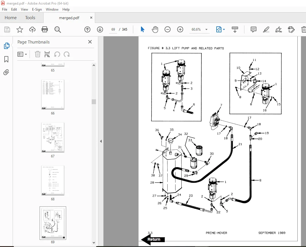
Figure # 3 3 Lift Pump and Related Parts 69
Figure # 3 4 Two/Three Spool Control Valve Assembly 71
Figure # 3 5 24 Volt Lift Pump and Motor Assembly 73
Figure # 3 6 Lift Pump Assembly 75
Figure # 3 7 Two Stage Full Freelift Cylinders and Related Parts 77
Figure # 3 8 Cylinder Assembly 79
Figure # 3 9 Cylinder Assembly 81
Figure # 3 10 Two Stage Cylinder and Related Parts 83
Figure # 3 11 Two Stage Lift Cylinder Assembly 85
Figure # 3 12 Three Stage Cylinder and Related Parts 87
Figure # 3 13 Three Stage Staging Cylinder Assembly 89
Figure # 3 14 Three Stage Freelift Cylinder Assembly 91
Figure # 3 15 Tilt Cylinder and Related Parts 93
Figure # 3 16 Tilt Cylinder Assembly 95
Figure # 3 17 Two Stage Full Freelift Sideshifter Hydraulic Assembly 97
Figure # 3 18 Hose Reel and Related Parts 99
Figure # 3 19 Dual Elbow Swivel Assembly 101
Figure # 3 20 Gleason Hose Reel Assembly 103
Figure # 3 21 Power Steering Hydraulic Assembly 105
Figure # 3 22 Torque Generator Assembly 107
Figure # 3 23 Power Steering Pump and Motor Assembly 109
Figure # 3 24 Power Steering Pump Assembly 111
Figure # 3 25 Remote Lift/Lower Control Installation 113
Figure # 4 1 Shielding and Frame Assembly 115
Figure # 4 2 Control Valve Mounting Assembly 117
Figure # 4 3 Slide Link Installation 119
Figure # 4 4 Load Wheel Assembly 121
Figure # 5 1 RC-30 Two Stage Full Freelift Mast Installation 123
Figure # 5 2 RC-30 Two Stage Full Freelift Outer Column Assembly 125
Figure # 5 3 RC-30 Two Stage Full Lift Inner Column Assembly 127
Figure # 5 4 RC-30 Two Stage Freelift Cylinder Assembly and Related Parts 129
Figure # 5 5 RC-30 Two Stage Lift Frame and Load Backrest Assembly 131
Figure # 5 6 Sideshifter Assembly 133
Figure # 5 7 Fork Assembly 135
Figure # 5 8 Two Stage Mast Installation 137
Figure # 5 9 Two Stage Outer Column Assembly 139
Figure # 5 10 Two Stage Inner Column Assembly 141
Figure # 5 11 Two Stage Cylinder Assembly and Related Parts 143
Figure # 5 12 Two Stage Lift Frame and Load Backrest Assembly 145
Figure # 5 13 Three Stage Mast Installation 147
Figure # 5 14 Three Stage Outer Column Assembly 149
Figure # 5 15 Three Stage Intermediate Column Assembly 151
Figure # 5 16 Three Stage Inner Column Assembly 153
Figure # 5 17 Three Stage Freelift Cylinder Installation 155
Figure # 5 18 Three Stage Lift Frame and Load Backrest Assembly 157
Figure # 6 1 Special Tools and Lubrications 159
Back Cover 161
Front Cover 162
Parts Ordering Instructions 163
General Information 164
Alphabetical Index 165
Figure # 0 1 Decals and Parts Assembly 169
Figure # 0 2 Parts List Index 171
Figure # 1 1 Transmission and Drive Motor Installation 175
Figure # 1 2 Transmission Assembly, Part II 177
Figure # 2 1 EV-100/EV-1 SCR Master Control Switch (24455-01) 179
Figure # 2 2 EV-100 SCR Electrical Schematic 181
Figure # 2 3 EV-100 SCR Electrical Schematic Symbols 182
Figure # 2 4 EV-100 SCR Control Wiring 183
Figure # 2 5 EV-100 SCR Power Component Wiring 185
Figure # 2 6 EV-100 SCR Contactor Panel Assembly (28059-00) 187
Figure # 2 7 EV-100 SCR Control Panel (27691-01) 189
Figure # 2 8 EV-100LX SCR Forward & Rearward Contactor Assembly (27692-00) 191
Figure # 2 9 EV-100LX SCR Contactor Assembly (27693-02) 193
Figure # 2 10 EV-100LX SCR Power Steering Contactor Assembly (23015-01) 195
Figure # 2 11 Power Connector Assembly 197
Figure # 2 12 Lift Pump Motor Assembly (OHIO D-4608214XWF07, 300284-000) 199
Figure # 2 13 Drive Motor Assembly (G E 5BT1322, 27903-00) 201
Figure # 2 14 Power Steering Pump Motor Assembly (Prestolite MKG-4201, 204306) 203
Figure # 2 15 Limit Switch Wiring Harness Assembly 205
Figure # 2 16 Warning Light Assembly (29030-01, 24 Volt) 207
Figure # 2 17 Warning Light Assembly (29030-01, 24 Volt) 209
Figure # 3 1 Hydraulic Schematic 211
Figure # 3 2 Hydraulic Schematic Symbols 212
Figure # 3 3 Lift Pump and Related Parts 213
Figure # 3 4 Two Spool Control Valve Assembly (24924-00) & Three Spool Control Valve Assembly (24925-00) 215
Figure # 3 5 Lift Pump and Motor Assembly (300336-000) 217
Figure # 3 6 Lift Pump Assembly (200037) 219
Figure # 3 7 Two Stage Full Free Lift Cylinders and Related Parts 221
Figure # 3 8 Two Stage Full Free Lift Cylinders Assembly, 1-1/8 inch (24477-XX) 223
Figure # 3 9 Two Stage Full Free Lift Cylinders Assembly, 2-3/4 inch (24517-XX) 225
Figure # 3 10 Two Stage Cylinders and Related Parts 227
Figure # 3 11 Two Stage Lift Cylinder Assembly (RC-30 300744-XXX) (RC-40 300745-XXX) 229
Figure # 3 12 Three Stage Cylinder and Related Parts 231
Figure # 3 13 Three Stage Staging Cylinder Assembly (28131-XX) 233
Figure # 3 14 Three Stage Freelift Cylinder Assembly (28150-XX) 235
Figure # 3 15 Tilt Cylinder and Related Parts 237
Figure # 3 16 Tilt Cylinder Assembly (25635-XX) 239
Figure # 3 17 Two Stage Full Free Lift Sideshifter Hydraulic Assembly 241
Figure # 3 18 Hose Reel and Related Parts 243
Figure # 3 19 Dual Elbow Swivel Assembly (25623-00)\ 245
Figure # 3 20 Gleason Hose Reel Assembly 247
Figure # 3 21 Power Steering Hydraulic Assembly 249
Figure # 3 22 Torque Generator Assembly (26125-00) 251
Figure # 3 23 Power Steering Pump and Motor Assembly 253
Figure # 3 24 Power Steering Pump Assembly 255
Figure # 3 25 Remote Lift/Lower Control Installation 257
Figure # 4 1 Steering Linkage 259
Figure # 4 2 Articulating Plate Assembly and Related Parts 261
Figure # 4 3 Steering Assembly 263
Figure # 4 4 Power Steering Gear Box 265
Figure # 4 5 Forward Gear Reduction Steering Gear Box Assembly 267
Figure # 4 6 Reverse Chain Reduction Steering Gear Box Assembly 269
Figure # 4 7 Master Control Switch Handle Assembly 271
Figure # 4 8 Control Valve Mounting Assembly 273
Figure # 4 9 Slide Link Installation 275
Figure # 4 10 Load Wheel Assembly 277
Figure # 4 11 Brake Linkage 279
Figure # 4 12 Brake Slave Cylinder Assembly (25088-00) 281
Figure # 4 13 Brake Master Cylinder Assembly (25083-00) 283
Figure # 4 14 Shielding and Frame Assembly 285
Figure # 5 1 RC-30 Two Stage Full Freelift Mast Installation 287
Figure # 5 2 RC-30 Two Stage Full Freelift Outer Column Assembly 289
Figure # 5 3 RC-30 Two Stage Full Freelift Inner Column Assembly 291
Figure # 5 4 RC-30 Two Stage Full Freelift Cylinder Assembly and Related Parts 293
Figure # 5 5 RC-30 Two Stage Full Freelift Lift Frame and Load Backrest Assembly 295
Figure # 5 6 Sideshifter Assembly (25411-00) 297
Figure # 5 7 Fork Assembly (25008-XX) 299
Figure # 5 8 Two Stage Mast Installation 301
Figure # 5 9 Two Stage Outer Column Assembly 303
Figure # 5 10 Two Stage Inner Column Assembly 305
Figure # 5 11 Two Stage Cylinder Assembly and Related Parts 307
Figure # 5 12 Two Stage Lift Frame and Load Backrest Assembly 309
Figure # 5 13 Three Stage Mast Installation 311
Figure # 5 14 Three Stage Outer Column Assembly 313
Figure # 5 15 Three Stage Intermediate Column Assembly 315
Figure # 5 16 Three Stage Inner Column Assembly 317
Figure # 5 17 Three Stage Freelift Cylinder Installation 319
Figure # 5 18 Three Stage Lift Frame and Load Backrest Assembly 321
Figure # 7 1 Battery Lift Interrupt “E” EV-100LX SCR Electrical Schematic 323
Figure # 7 2 Battery Lift Interrupt “E” EV-100LX SCR Electrical Schematic Symbols 324
Figure # 7 3 Battery Lift Interrupt “EE” EV-100LX SCR Electrical Schematic 325
Figure # 7 4 Battery Lift Interrupt “EE” EV-100LX SCR Electrical Schematic Symbols 326
Figure # 7 5 Battery Lift Interrupt Installation 327
Numerical Index 330
Back Cover 345
DESCRIPTION:
BT Prime-Mover RC-30 RC-40 Electric Counterbalanced Rider Truck Parts Manual – PDF DOWNLOAD
Manual Number RC30/40P8909
- When you order, supply the part number, quantity, model and serial numbers of your machine. Supplying this information will assure prompt, efficient handling of your order. The pictorial reference number is not needed and including it can only add confusion.
- Since your dealer carries many parts in stock and maintains up-to-date prices on all parts, he will be able to process your order immediately. If, for some reason, the part is not in stock, he will order it from the factory. In either event, he maintains a current file of service manuals, which give all available parts ordering or technical information.
- All prices are FOB factory in Muscatine, Iowa. Shipping charges are added to the price of the part shipping from the factory.
WHERE TO ORDER:
Always order parts from the dealer who sold you your Prime-Mover. If it is necessary for the dealer to order parts from the factory, he is able to get prompt service for you. Parts are shipped in accordance with shipping instructions given on the order.
S.V 01/02/2025