BT Prime-Mover RC-30B RC-40B RC-50B ELECTRIC TRUCK Repair Manual PDF
$28.95
BT Prime-Mover RC-30B RC-40B RC-50B ELECTRIC STAND-UP RIDER COUNTERBALANCED TRUCK Repair Manual – PDF DOWNLOAD
Manual Part Number 301981-000
Effective Serial Number 93-17290
Description
BT Prime-Mover RC-30B RC-40B RC-50B ELECTRIC STAND-UP RIDER COUNTERBALANCED TRUCK Repair Manual – PDF DOWNLOAD
FILE DETAILS:
BT Prime-Mover RC-30B RC-40B RC-50B ELECTRIC STAND-UP RIDER COUNTERBALANCED TRUCK Repair Manual – PDF DOWNLOAD
Language : English
Pages : 239
Downloadable : Yes
File Type : PDF
IMAGES PREVIEW OF THE MANUAL:
TABLE OF CONTENTS:
BT Prime-Mover RC-30B RC-40B RC-50B ELECTRIC STAND-UP RIDER COUNTERBALANCED TRUCK Repair Manual – PDF DOWNLOAD
Manual Part Number 301981-000
Effective Serial Number 93-17290
Front Cover 2
Contents 4
Wiring Diagrams 4
Hydraulic Schematics 4
General Information 6
Troubleshooting 6
Maintenance 6
Specifications Tables 8
Torque Specifications 8
Introduction 12
The Service Manual 12
How to Use this Manual 12
The Equipment 13
Safety Precautions – Maintenance & Repair 14
Specifications Tables 18
General 18
Capacities 18
Steering System 18
Tires 18
Batteries 18
Travel Speeds & Current Draw 19
Lifting Speeds 19
Lift & Tilt System 19
Torque Specifications 20
Contents 22
Introduction 22
Maintenance Procedures 22
Introduction 24
General 24
Towing a Disabled Lift Truck 24
Lifting a Disabled Lift Truck 24
Putting the Lift Truck on Blocks 25
Scheduled Maintenance and Inspections 26
Scheduled Maintenance & Inspections Table 27
Maintenance Procedures Every 8 Hours or Daily 28
General 28
SRO Circuit 28
General Functions 28
Battery 28
Charging the Battery 29
Changing the Battery 29
Battery Connector 29
Inspection 29
Battery Gates 29
Inspection 29
Upright 30
Hydraulic System 31
Checking for Leaks 31
Drive Unit 31
Checking Operation 31
Forks 31
Inspection 31
Wheels & Tires 32
Inspection 32
Drive Wheel – Removal & Installation 32
Steer Wheel – Removal & Installation 32
Changing Tires 32
Brake Pedal 33
Inspect & Lubricate 33
Brake Switch 33
Check for Operation 33
Brakes 33
Check Operation 33
Controls/Horn 33
Check Operation 33
Steering System 33
Check Operation 33
Lights 33
Inspect 33
Decals 34
Inspect 34
Maintenance Procedures Every 40 Hours or 5 Days 35
Battery 35
Cleanliness 35
Water Level 35
Lift Chains 35
Inspect 36
Hydraulic System 36
Check Oil Level 36
Maintenance Procedures Every 350 Hours or 60 Days 37
Battery 37
Charging 37
Lift Chains 37
Lubrication 37
Check Tension 37
Upright 38
Lubrication 38
Hydraulic System 38
Breather Cap 38
Drive Unit 38
Check Fluid Level 38
Brakes 39
Check Fluid 39
Hinges & Levers 39
Steering 39
Motor Brushes 40
Drive Motors 40
Lift Pump Motor 40
Steering Pump Motor 41
Contactor Tips 41
Maintenance Procedures Every 2000 Hours or 360 Days 42
Hydraulic System 42
Change the Hydraulic Oil 42
Change the Hydraulic Oil Filter 42
Breather Cap 42
Drive Units 42
Wheels & Tires 43
Lubricate Wheel Bearings 43
Brakes 43
Brake Shoes 43
Contents 44
Wiring Diagrams 44
Contents 56
Introduction 56
Maintenance 56
Introduction 58
General 58
Safety 58
Maintenance 59
Installation 59
Removal 59
Charging the Battery 60
Normal Charge 60
Equalizing Charge 60
Cleaning the Battery 60
Hydrometer Use 61
Voltage Check 61
Adding Water 61
Battery History Record 61
Contents 64
Troubleshooting Tables 64
Power Section 66
Brake System 67
Steering System 69
Hydraulic System 70
Hydraulic Gear Pump 72
Uprights 74
Main Control Valve 75
Industrial Battery 76
Contents 78
Power Section 78
Brake System 78
Steering System 78
Controls Mechanical 78
Electrical System 78
Hydraulic System 78
Elevating Section 78
Contents 80
Drive Unit Assembly 80
Introduction 80
Repairs 80
Disassembly 80
Assembly 80
Installation 80
DC Motor Repair 80
Introduction 80
Repairs 80
Hydraulic Pump Motor 80
Power Steering Motor 81
DC Motor Maintenance 81
Introduction 81
Brush and Commutator Inspection 81
Brush Replacement 81
Tests for a Damaged Field and Armature 81
Brush Holder Test 81
Drive Unit Assembly 82
Introduction 82
Description 82
Repairs 82
Removal – General 82
Removal – Complete Drive Assembly 82
Removal – Final Drive Assembly 83
Disassembly 84
Single Stage Gear Housing 84
Final Drive Unit 84
Figure 3 5 – Drive Unit 85
Inspection 86
Assembly 86
Final Drive Unit 86
Single Stage Gear Housing 87
Final Drive Assembly 88
Installation 88
Complete Drive Assembly 88
Final Drive Assembly 89
DC Motor Repair 90
Introduction 90
Repairs 90
Drive Motor 90
Disassembly 92
Checks and Inspection 92
Assembly 92
Installation 92
Hydraulic Pump Motor 93
Removal 93
Disassembly 94
Checks and Inspection 94
Assembly 94
Installation 94
Power Steering Motor 94
Removal 94
Figure 3 14 – Hydraulic Pump Motor 95
Disassembly 96
Checks and Inspection 96
Assembly 96
Installation 97
DC Motor Maintenance 98
Introduction 98
Brush and Commutator Inspection 98
Figure 3 17 Normal Commutator Surfaces 99
Figure 3 18 Commutator Problems 100
Normal Commutator Surface 102
Brush Replacement 102
Tests for a Damaged Field and Armature 103
Armature Tests 103
Test for an Open Circuit 103
Test for Short Circuit – Armature Winding 103
Test for Short Circuit – Armature 103
Field Coil Tests 103
Test for an Open Circuit 103
Test for a Short Circuit in a Field 104
Test for a Short Circuit Between the Field and the Motor Case 104
Brush Holder Test 104
Contents 106
The Brake Assembly 106
Repairs 106
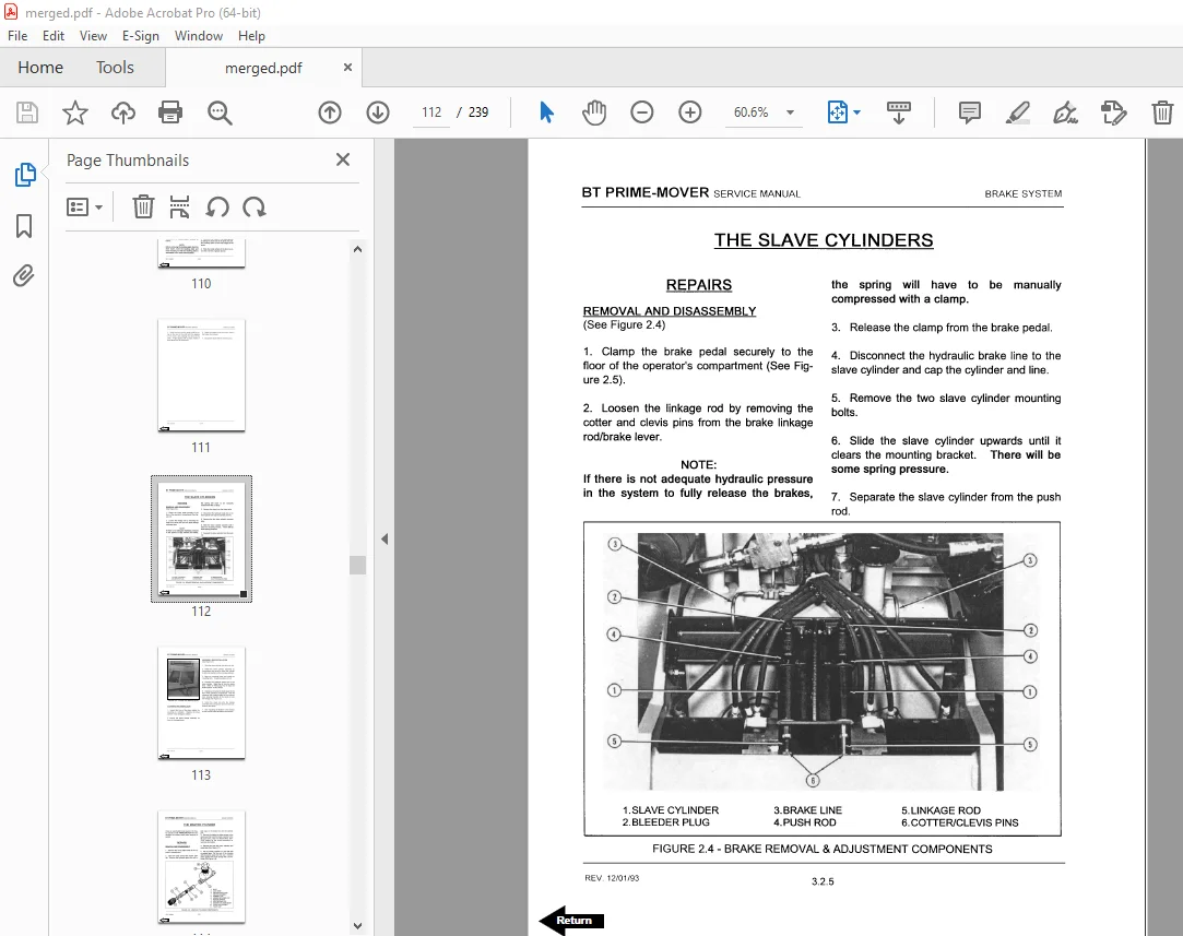
The Slave Cylinders 106
Repairs 106
The Master Cylinder 106
Repairs 106
Checks and Adjustments 106
The Brake Assembly 108
Description 108
Repairs 109
Removal and Disassembly 109
Cleaning and Inspection 110
Assembly and Installation 110
The Slave Cylinders 112
Repairs 112
Removal and Disassembly 112
Cleaning and Inspection 113
Assembly and Installation 113
The Master Cylinder 114
Repairs 114
Removal and Disassembly 114
Cleaning and Inspection 115
Assembly and Installation 115
Checks and Adjustments 116
Removing the Air from the Brake System 116
Adjusting the Brakes 116
Adjusting the Brake Pedal and Master Cylinder 117
Contents 118
Introduction 118
Repairs 118
Steering Fork Assembly 118
Steer Wheel 118
Steering Chain 118
Torque Generator 118
Additional Checks and Inspections 118
Steering System 120
Introduction 120
Description 120
Repairs 121
Steering Fork Assembly 121
Removal 121
Cleaning and Inspection 122
Installation 122
Steer Wheel 123
Removal 123
Installation 124
Steering Chain 124
Torque Generator 125
Removal 125
Disassembly 125
Cleaning 125
Assembly 125
Figure 3 7 Torque Generator and Gear Mount Assembly 126
Installation 127
Figure 3 8 The Torque Generator 127
Figure 3 9 Torque Generator Timing 128
Additional Checks and Inspections 129
Contents 130
Mechanical Controls 130
Control Handles 130
Battery Disconnect 130
Mechanical Controls 132
Control Handles 132
Control Linkage Adjustment 132
Figure 4 1 Control Handles 132
Multi-Function Control Handle and Switch Replacement 133
Battery Disconnect 133
Battery Disconnect Adjustment 133
Figure 4 2 Adjusting the Control Linkage 133
Contents 136
GE EV100 LXT Controls 136
General 136
Maintenance 136
Instructions EV100 LX/LXT SCR Controls 138
EV100 LX/LXT Dual Motor Control 140
Terminal Connections for LX/LXT Logic Cards 141
EV100 LX/LXT Specifications 142
Features 143
EV100 LX/LXT Current Limit Curves 146
Basics of Circuit Operation 147
Control Features 148
Oscillator 148
Current Limit 148
Plugging 149
Pedal Position Plug 149
Ramp Start 149
Full Power Transition 149
Control Acceleration and 1A Time 149
1A Current Drop Out 149
Static Return to Off 149
Accelerator Volts Hold-Off 149
Coil Driver Modules 150
1A Thermal Hold Off 150
Must Pulse to Time 150
Pulse Monitor Trip 150
Thermal Protector 150
Low Voltage 151
Field Weakening 151
Dual Motor Operation 151
Dual Motor In-Board Wheel Reversal 152
Dual Motor Two Speed Limit 152
Top Speed (Motor Volts) Limit 152
Steer Pump Contactor Time Delay 152
Constant Current Coil Drivers and Internal Coil Suppression 152
Hour Meter Readings 152
Internal Resistance Compensation 152
Truck Management Module (TMM1) 153
Truck Management Module (TMM2) 153
Stored Status Code 153
On Board Diagnostics 153
Battery Discharge Indication 153
Handset 153
General Maintenance Instructions 154
Troubleshooting Instructions 155
Instructions – Status Codes 156
Checking Components 174
Main Logic Card 174
Capacitor 1C 175
Potentiometer in Accelerator 175
SCR’s (1REC, 2REC, 5REC) 175
Rectifiers (3REC, 4REC, Diode Blocks) 176
Thermal Protector (TP) 176
Filter Block 177
1X Choke and Reactor T3 – T4 177
Replacement of EV-100 Components 178
Instructions – EV100 Handset 179
GE EV100 LXT BT Prime-Mover Factory Settings – All Models 184
Contents 186
Introduction 186
Repairs 186
Hydraulic Gear Pumps 186
The Lift Cylinders 186
The Tilt Cylinders 187
The Main Control Valve 187
The Hydraulic System 188
Introduction 188
Description 188
Operation 188
Multi-Lever Configuration 189
Multi-Function Handle Configuration 189
Repairs 190
Hydraulic Pump 190
Removal 190
Installation 190
Power Steering Pump 190
Installation 190
Multi-Lever Main Control Valve 191
Removal 191
Installation 191
Multi-Function Handle Main Control Valve 192
Removal 192
Installation 192
Multi-Function Solenoid Selector Valve 193
Removal 193
Installation 193
Hydraulic Pump Switches 193
Adjustment 193
Hydraulic Gear Pumps 195
Introduction 195
Description 195
Repairs 196
Seal Replacement – Power Steering Pump 196
Checking for Air in the System 196
The Lift Cylinders 197
Introduction 197
Description 197
Flow Control Valve & Flow Fuses 197
Repairs 198
Removal of the Lift Cylinder – Two Stage Uprights 198
Figure 6 7 Two Stage Upright 199
Figure 6 8 Three Stage Upright 200
Removal of the Lift Cylinders – Three Stage Uprights 201
Disassembly 202
Assembly 203
Figure 6 14 Lift Cylinder – Two Stage Upright 204
Figure 6 15 Inner Lift Cylinder – Three Stage Upright 204
Figure 6 16 Inner Lift Cylinder – Three Stage Upright 205
Figure 6 17 Outer Lift Cylinder – Three Stage Upright 205
Installation of the Lift Cylinder – Two Stage Uprights 206
Installation of the Lift Cylinders – Three Stage Uprights 206
The Tilt Cylinders 208
Introduction 208
Description 208
Repairs 208
Removal 208
Disassembly 208
Cleaning & Inspection 208
Assembly 209
Installation 209
Checks and Adjustments 210
Checking for Leakage 210
Adjusting the Tilt Angle 210
The Main Control Valve 211
Introduction 211
Description 211
Figure 6 21 Main Control Valve 212
Operation 213
Lift Section 213
Tilt Section 213
Solenoid Valve for Auxiliary Function 214
Relief Valve 214
Repairs 215
Removal & Disassembly 215
Cleaning & Inspection 216
Assembly 216
Checks & Adjustments 216
Primary Relief Valve 216
Auxiliary Function Relief Valve 217
Contents 218
Introduction 218
Uprights Repair 218
Forks 218
Carriage 218
Uprights 218
Side Shift Carriage 218
Side Shift Carriage – Checks and Adjustments 218
Hose Reel Assembly 218
Checks and Adjustments 218
The Elevating Section 220
Introduction 220
Description 220
Simplex Uprights 220
Triplex Uprights 220
Figure 7 1 Flow Control Valves and Flow Fuses 221
Figure 7 2 Two Stage Uprights 222
Figure 7 3 Three Stage Upright 223
Uprights Repair 224
Forks 224
Carriage 224
Removal 224
Installation 225
Uprights 226
Removal 226
Disassembly 227
Cleaning and Inspection 228
Assembly 230
Installation 230
Upright Adjustment 231
Carriage Adjustment 231
Sideshift Carriage 232
Removal 232
Repairs 232
Installation 232
Sideshift Carriage Checks and Adjustments 232
Adjusting the Restrictor Cartridge 232
Lower Hook Adjustment 233
Hose Reel Assembly 233
Removal 233
Installation 234
Checks and Adjustments 234
Leaks Outside the Hydraulic Lift System 234
Leaks Inside the Hydraulic Lift System 234
Adjusting the Tilt Angle 235
Lift Chain Adjustments 235
Back Cover 239
DESCRIPTION:
BT Prime-Mover RC-30B RC-40B RC-50B ELECTRIC STAND-UP RIDER COUNTERBALANCED TRUCK Repair Manual – PDF DOWNLOAD
Manual Part Number 301981-000
Effective Serial Number 93-17290
INTRODUCTION:
THE SERVICE MANUAL:
This manual is a reference source for technical information on the BT PRIME-MOVER electric stand-up counterbalance lift truck equipment you have purchased. The intent is to utilize this manual to properly maintain and/or repair the BT PRIME-MOVER equipment.
HOW TO USE THIS MANUAL:
The Tables of Contents provide easy location of all subject matter within the manual. Individual chapter contents lists are located at the beginning of each chapter, following the reference tabs.
THE EQUIPMENT:
- The BT PRIME-MOVER electric stand-up counterbalance lift truck is powered by a 36 volt industrial battery. It is available in 3,000, 4,000, and 5,000 pound capacities with either simplex, triplex, or quad mast configurations. The tractor has a rear-entry, forward-stance configuration. A wide variety of attachments (forks, clamps, rotators, side shift, push-pull, etc.) are also available options. With the numerous standard and optional features that are available, the BT PRIME-MOVER trucks adapt to a wide variety of industrial material handling needs.
- The Models RC30B, RC40B, and RC50B have the ability to maneuver in tight quarters (box cars for example), will easily negotiate steep ramps (15%), and are readily adaptable for dock work.
S.V 01/02/2025