BT Prime-Mover RC SERIES TRUCKS RC-20 RC-25 RC-30 RC-40 Operating & Parts Manual PDF
$28.95
BT Prime-Mover RC SERIES TRUCKS RC-20 RC-25 RC-30 RC-40 Operating Maintenance & Parts Manual – PDF DOWNLOAD
Description
BT Prime-Mover RC SERIES TRUCKS RC-20 RC-25 RC-30 RC-40 Operating Maintenance & Parts Manual – PDF DOWNLOAD
FILE DETAILS:
BT Prime-Mover RC SERIES TRUCKS RC-20 RC-25 RC-30 RC-40 Operating Maintenance & Parts Manual – PDF DOWNLOAD
Language : English
Pages : 375
Downloadable : Yes
File Type : PDF
IMAGES PREVIEW OF THE MANUAL:
TABLE OF CONTENTS:
BT Prime-Mover RC SERIES TRUCKS RC-20 RC-25 RC-30 RC-40 Operating Maintenance & Parts Manual – PDF DOWNLOAD
310665-000 1971_April
301073-000 1974_February
301073-002 Before 1974_March
301073-000 After 1974_March Effective Serial Number 1504
301073-003 1982_March
Front Cover 2
Warranty 3
New Owners 4
Contents 4
Specifications for RC Truck 4
Operating Rules and Instructions 5
Periodic Maintenance Chart 11
Lubrication Chart 12
Maintenance Instructions 13
Service and Disassembly Instructions 17
Parts Ordering Instructions 20
Parts List and Service Reference Index 21
Main Frame, Shielding, Misc 23
Drive Mounting 25
24 Volt Transmission Service Parts 27
Drive Motor Service Parts for D-25901 29
Drive Motor Service Parts for D-25968 30
Brake Linkage 31
Steering Linkage 32
Steering Assembly 33
Steering Reduction 34
Single Pump Hydraulic Piping RC-20,25,30 35
Dual Pump Hydraulic Piping RC-30,40 37
Hydraulic Control Valve 39
Hydraulic: Valve Mounting, Reservoir Mounting, Motor Mounting 40
Hydraulic Pump/Motor Assembly for P-25428 41
Pump/Motor Assembly for P-25428 42
Tilt Cylinder Assembly 43
Lift Cylinder – 3 Stage White Mast 45
Lift Cylinder – Prime-Mover Mast 47
Mast – Prime-Mover 49
Retractable Overhead Guard 52
Mast – Knickerbocker 53
Mast – White 55
G E SCR Electrical Schematic 57
Electrical Schematic Symbols 58
Control Wiring for G E Model EV-1 System 59
Power Wiring G E Model EV-1 61
G E Model EV-1 Control 63
Contactor Panel G E Model EV-1 64
EV-1 Forward/Reverse Contactor 65
EV-1 1A, P & FW Contactor 67
Control Handle Master Switch 69
Cold Storage Diagram/Components 70
Auxiliary Hydraulic Valve Parts Breakdown 72
Brudi Side Shifter 73
Hydraulic Cylinder for Brudi Side Shifter 74
Brudi Hose Reel Assembly for Prime-Mover Masts 75
BRudi Hose Reel 76
Gleason Hose Reel Assembly for 3 Stage Masts 77
Gleason Hose Reel 78
Service Guide 79
Back Cover 83
Front Cover 84
Warranty 85
To New Prime-Mover Owners 86
Contents 86
Operating Instructions 87
Preliminary Service 87
Operation 87
Controls 87
Key Switch 87
Dead Man Brake 87
Direction Control 87
Horn 88
Lift Lower Control 88
Tilt Control 88
Auxiliary Hydraulic Control 88
Service References 88
Periodic Maintenance Chart 89
Daily 89
Weekly 89
Annually 89
Monthly 89
Semi-Annually 89
Lubrication Chart 90
Maintenance Instructions 91
Battery 91
Electrical Wiring 91
Control Switches 91
Potentiometer 91
Deadman Brake 92
Interlock Switch 92
Steering Chain 92
Transmission Rollers 93
Contactor Points 93
Motor Commutator 93
Drive Gear Adjustments 93
Hydraulic System 93
Hydraulic Pump/Motor 93
Hydraulic Valve Switch 94
Lift Cylinder 94
Lift Chain 94
Tilt Cylinder 94
Articulating Plate 94
Service and Disassembly Instructions 95
Mast 95
Tilt Cylinder 95
Lift Cylinder 95
Floor Plate 96
Transmission Assembly 96
Articulating Plate 96
Support Wheel Steering Linkage 96
Drive Wheel 96
Drive Motor 97
Electrical Panels 97
Steering Gear Box 97
Lift Frame 97
Inner Column 97
Brake Discs 97
Parts Ordering Instructions 98
Field Modifications 98
Parts List Index 99
Main Frame, Shielding, Misc 101
Drive Mounting 103
24 Volt Transmission 105
Drive Motor Service Parts 107
Steering Linkage 108
Steering Assembly 109
Steering Reduction 110
Hydraulic Piping RC-20, 25, 30 (Single Pump) 111
Hydraulic Piping RC-30 (Dual) and RC-40 113
Hydraulic Valve (2 & 3 Spool) 115
Hydraulic: Valve Mounting, Reservoir Mounting, Motor Mounting 116
Hydraulic Pump 117
Motor for P-25428 Pump/Motor Assembly 118
Tilt Cylinder Assembly 119
Lift Cylinder 120
Lift Cylinder Assembly 122
Mast – 2 Stage 123
Knickerbocker Trirol 3 Mast 125
White Masts 127
Square “D” Power Wiring 128
Control Wiring for G E System 129
Auxiliary Hydraulic Valve Parts Breakdown 130
Brudi Sideshifter 131
Hydraulic Cylinder for Brudi Sideshifter 132
Brudi Hose Reel Assembly 133
Brudi Hose Reel 134
Cascade Hose Reel Assembly (for 3 Stage Masts) 135
Outboard Spring Style Hose Reels 136
Inboard Spring Style Hose Reels 136
Service Guide 137
Back Cover 139
Front Cover 140
Warranty 141
New Prime-Mover Owner 142
Contents 142
Specifications 142
Operating Rules and Instructions 143
Maintenance Chart 149
Lubrication Chart 150
Maintenance Instructions 151
Service and Disassembly Instructions 155
Parts Ordering Instructions 158
Parts List and Service Reference Index 159
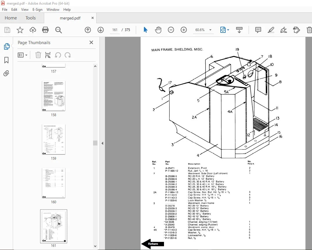
Main Frame, Shielding, Misc 161
Drive mounting 163
Transmission Service Parts 165
Drive Motor Service Parts for D-25901 167
Brake Linkage 169
Steering Linkage 170
Steering Assembly 171
Steering Reduction 172
Hydraulic Piping, Single Pump 173
Hydraulic Piping, Dual Pump 175
Hydraulic Control Valve 177
Hydraulic: Valve Mounting, Reservior Mounting, Motor Mounting 178
Hydraulic Pump 179
Motor Assembly for P-25428 180
Tilt Cylinder Assembly 181
Lift Cylinder – White 3 Stage Mast 183
Lift Cylinder – Prime-Mover 185
Mast – 2 Stage Prime-Mover 187
Mast – 3 Stage Knickerbocker 191
Mast – 3 Stage White 193
G E SCR Electrical Schematic – Model EV-1 195
Electrical Schematic Symbols 196
Control Wiring for G E EV-1 System 197
Power Wiring for G E EV-1 System 199
Control, G E EV-1 201
Contactor Panel, G E EV-1 202
Control Handle, EV-1 A-25314 203
Auxiliary Hydraulic Valve Parts 204
Brudi Sideshifter 205
Brudi Sideshifter Cylinder Assembly 206
Brudi Hose Reel Assembly for Prime-Mover Masts 207
Brudi Hose Reel Assembly 208
Gleason Hose Reel Assemby for 3 Stage Masts 209
Gleason Hose Reel Assembly 210
Service Guide 211
Back Cover 219
Front Cover 220
Warranty 221
To New Owners 222
Operating Rules and Instructions 223
Lubrication Chart 228
Maintenance Instructions 229
Service and Disassembly Instructions 232
Parts Ordering Instructions 235
RC20 Truck Specifications 236
RC25 Truck Specifications 237
RC30 Truck Specifications 238
RC40 Truck Specifications 239
Figure # 1 Decal and Parts Assembly 240
Figure # 2 Parts List and Service Reference Index 241
Figure # 3 Shielding Assembly 243
Figure # 4 Drive Mounting 245
Figure # 5 14:1 Transmission Assembly with MKU-4005 Drive Motor 247
Figure # 6 Motor Assembly 249
Figure # 7 Brake Linkage 250
Figure # 8 Slave Cylinder Assembly 251
Figure # 9 Master Cylinder Assembly 252
Figure # 10 Steering Linkage 253
Figure # 11 Steering Assembly 254
Figure # 12 Power Steering Gear Box 255
Figure # 13 Torque Generator 256
Figure # 14 Forward Gear Reduction Steering Gear Box, Reverse Chain Reduction Steering Gear Box 257
Figure # 15 GE Electrical Schematic – Model EV-1 258
Figure # 16 Electrical Symbols 259
Figure # 17 Control Wiring for GE Model EV-1 System 260
Figure # 18 Power Component Assembly 261
Figure # 19 SCR and Contactor Panel Assembly 262
Figure # 20 EV-1 SCR Control 263
Figure # 21 Transformer Assembly 264
Figure # 22 Rectifier Heat Sink Assembly 265
Figure # 23 GE Contactor Assembly 266
Figure # 24 Power Steering Contactor Assembly 267
Figure # 25 GE Contactor Assembly 268
Figure # 26 Warning Light Assembly 269
Figure # 27 Connector Assembly 270
Figure # 28 Handle Assembly 271
Figure # 29 Master Control Switch Assembly 272
Figure # 30 Master Control Switch Assembly 273
Figure # 31 Cold Storage Diagram/Components 274
Figure # 32 Hydraulic Schematic 275
Figure # 33 Hydraulic Schematic Symbols 276
Figure # 34 Hydraulic Assembly RC-20, 25, 30 (2 stage) 277
Figure # 35 Hydraulic Assembly (3 stage) 279
Figure # 36 Hydraulic Assembly – Part # 1 280
Figure # 37 Hydraulic Assembly Part # 2 281
Figure # 38 Staging Cylinder Assembly 283
Figure # 39 Freelift Cylinder Assembly 284
Figure # 40 Hydraulic Assembly Part # 3 285
Figure # 41 Pump and Motor Assembly 286
Figure # 42 Motor Assembly 287
Figure # 43 Pump Assembly 288
Figure # 44 Valve Mounting Assembly 289
Figure # 45 Control Valve Assembly 290
Figure # 46 Control Valve Assembly 291
Figure # 47 Hydraulic Pump and Motor 292
Figure # 48 Pump Assembly 293
Figure # 49 Motor Assembly 294
Figure # 50 Motor Assembly 295
Figure # 51 Tilt Cylinder Assembly and Related Parts 296
Figure # 52 Tilt Cylinder Assembly 297
Figure # 53 Lift Cylinder and Related Parts 298
Figure # 54 2″ Lift Cylinder Assembly 299
Figure # 55 2 1/2″ Lift Cylinder Assembly 301
Figure # 56 2 3/4″ Lift Cylinder Assembly 303
Figure # 57 2 Stage Mast Assembly 305
Figure # 58 2 Stage Outer Column Assembly 306
Figure # 59 2 Stage Inner Column Assembly 307
Figure # 60 2 Stage Lift Cylinder and Related Parts 308
Figure # 61 Lift Frame and Load Backrest 309
Figure # 62 RC-20 (Only) Lift Frame and Load Backrest 310
Figure # 63 Mast Assembly (3 Stage) 311
Figure # 64 Lift Frame Assembly 312
Figure # 65 Inner Column Assembly (3 Stage) 313
Figure # 66 Freelift Cylinder Assembly (3 Stage) 314
Figure # 67 Intermediate Column Assembly (3 Stage) 315
Figure # 68 Outer Column Assembly (3 Stage) 316
Figure # 69 Fork Assembly 317
Figure # 70 Auxiliary Hydraulic Valve Parts Breakdown 318
Figure # 71 Brudi Sideshifter 319
Figure # 72 Hydraulic Cylinder for Brudi Sideshifter 320
Figure # 73 Gleason Hose Reel Assembly (3 Stage Masts) 321
Figure # 74 Gleason Hose Reel 35 Series 322
Figure # 75 Dual Elbow Swivel Assembly 323
Service Guide 325
Back Cover 327
Front Cover 328
Prime Mover Warranty 329
Contents 330
To New Prime-Mover Owners 330
Operating Instructions 331
Preparation for Service 331
Operation 331
Controls 331
Deadman 331
Direction Control 331
Lift-Lower Control 331
Tilt 331
Horn 331
Auxiliary Hydraulic Controls 331
Operator – Maintenance Instructions 332
Daily 332
Weekly 332
Monthly 332
Semi-Annually 332
Annually 332
Battery Care 332
Maintenance Instructions 333
Battery 333
Electrical Wiring 333
Control Switches 333
Deadman Brake 333
Interlock Switch 333
Steering Chain 334
Transmission Rollers 334
Contactor Points 334
Motor Commutator 334
Hydraulic System 334
Hydraulic Valve Switch 334
Lift Cylinder 334
Lift Chain 334
Tilt Cylinder 334
Steering Linkage 334
Notes 335
Service Instructions 336
Remove the Mast 336
Remove the Tilt Cylinder 336
Assemble the Tilt Cylinder 336
Remove the Hydraulic Reservoir 336
Remove Cylinder Hoses 336
Remove the Hydraulic Lift Cylinder 336
Assemble the Hydraulic Lift Cylinder 336
Remove the Floor Plate 336
Remove the Transmission Assembly 336
Reassemble Transmission into Unit 336
Adjust the Transmission Eccentric Dowel 337
Remove the Support Wheel Steering Linkage 337
Remove the Support Wheels 337
Remove the Load Wheels 337
Remove the Drive Wheel 337
Remove Drive Motor 337
Remove SCR Panel 337
Remove the Sq “D” Contactor Panel 337
Remove Steering Gear Box 337
Remove Lift Frame 337
Remove the Inner Column 337
Replace the Brake Disc 337
Repair the Brake Cylinders 337
Remove the Handle Assembly 337
Notes 338
Parts Ordering Instructions 339
Notes 340
Lubrication Chart 342
Major Parts Listing 343
Stacker Frame Parts 344
Mast Assembly Parts List 346
Transmission Assembly 348
Drive Mounting 349
Hydraulic Cylinder Assembly 350
Lift Cylinder 350
Tilt Cylinder 351
Hydraulic Valve 352
Hydraulic Piping 354
Hydraulic Pump and Motor 355
Handle 356
Brake and Linkage 357
Steering Linkage 358
Steering 360
Support Wheels 361
Sheave Head 362
Power Wiring 363
Notes 364
Sq “D” SCR Panel 365
Sq “D” Contactor Panel 366
Notes 367
Control Wiring 369
Notes 370
Service Guide 373
Back Cover 375
DESCRIPTION:
BT Prime-Mover RC SERIES TRUCKS RC-20 RC-25 RC-30 RC-40 Operating Maintenance & Parts Manual – PDF DOWNLOAD
310665-000 1971_April
301073-000 1974_February
301073-002 Before 1974_March
301073-000 After 1974_March Effective Serial Number 1504
301073-003 1982_March
OPERATING RULES AND INSTRUCTIONS
OPERATOR QUALIFICATIONS
Only trained and authorized operators shall be permitted to operate a powered industrial truck. Operators of powered industrial trucks shall be qualified as to visual, auditory, physical, and mental ability to operate the equipment.
OPERATOR TRAINING
An effective operator training program should center around user company’s policies, operating conditions and trucks. The program should be presented completely to all new operators and not condensed for those claiming previous experience.
OPERATOR RESPONSIBILITY
Powered industrial truck operators shall abide by the following rules and practices.
GENERAL RULES ANO PRACTICES
A. Safeguard the Pedestrains at all times. Do not drive a truck up to anyone standing in front of a bench or other fixed object.
B. Do not allow anyone to Stand or pass under the elevated portion of any truck, whether loaded or empty.
C. Unauthorized passengers shall not be permitted to ride.
D. Do not put any part of the body between the uprights of the mast or outside the running lines of the truck.
E. When the operator is dismounted and within 25 feet (7600mm) of the truck which remains in his view, the load engaging means shall be fully lowered, controls neutralized and brakes set to prevent movement.
F. A powered industrial truck is unattended when the operator is 25 feet (7600mm) or more from the truck which remains in view, or whenever the operator leaves the truck and it is not in his view.
S.V 01/02/2025