BT Prime-Mover RR-30C Electric Reach Truck Parts Manual PDF
$28.95
BT Prime-Mover RR-30C Electric Reach Truck Parts Manual – PDF DOWNLOAD
Manual Part Number 300379-001
Description
BT Prime-Mover RR-30C Electric Reach Truck Parts Manual – PDF DOWNLOAD
FILE DETAILS:
BT Prime-Mover RR-30C Electric Reach Truck Parts Manual – PDF DOWNLOAD
Language : English
Pages : 226
Downloadable : Yes
File Type : PDF
IMAGES PREVIEW OF THE MANUAL:
TABLE OF CONTENTS:
BT Prime-Mover RR-30C Electric Reach Truck Parts Manual – PDF DOWNLOAD
Manual Part Number 300379-001
Front Cover 1
Parts Ordering Instructions 2
General Information 3
Alphabetical Index 4
Figure # 0 1 Decals and Parts Assembly 8
Figure # 0 2 Parts List Index 10
Figure # 1 1 Transmission and Drive Motor Installation 14
Figure # 1 2 Drive Motor and Brake Assembly 16
Figure # 1 3 Transmission Assembly (40011-01) Part # I 18
Figure # 1 4 Transmission Assembly (40011-00) Part # II 20
Figure # 2 1 “E” EV-100LX SCR Electrical Schematic 22
Figure # 2 2 “E” EV-100LX SCR Electrical Schematic Symbols 23
Figure # 2 3 “EE” EV-100LX SCR Electrical Schematic 24
Figure # 2 4 “EE” EV-100LX SCR Electrical Schematic Symbols 25
Figure # 2 5 Wiring Assembly for Cold Storage 26
Figure # 2 6 Wiring Harness Assembly 28
Figure # 2 7 Limit Switch Wiring Assembly 30
Figure # 2 8 Two Stage Mast Cable Assembly 32
Figure # 2 9 Three Stage Mast Cable Assembly 34
Figure # 2 10 Reach Cable Assembly 36
Figure # 2 11 EV-100LX Power Component Wiring 38
Figure # 2 12 EV-100LX TX SCR Control Panel Assembly (49399-00) & EV-100LX TT SCR Control Panel Assembly (49399-01) 40
Figure # 2 13 EV-100LX contactor Panel Assembly & Related Parts for “E” and “EE” 42
Figure # 2 14 EV-100LX Contactor Panel Assembly (24 Volt, 41757-01) & (36 Volt, 41757-02) 44
Figure # 2 15 EV-100LX SCR Forward & Rearward Contactor Assembly (27692-00) 46
Figure # 2 16 EV-100LX SCR 1A Contactor Assembly (27693-02) 48
Figure # 2 17 Lift Pump Contactor Assembly (24 Volt, 27693-02) & (36 Volt, 202169) 50
Figure # 2 18 EV-100LX SCR Auxiliary Pump Contactor Assembly (300073-000) 52
Figure # 2 19 Power Connector Assembly (24 Volt, 29855-24) (36 Volt, 49855-22) 54
Figure # 2 20 Lift Pump Motor Assembly, 24 Volt (27900-00, 5BT1324B54) G E & Lift Pump Motor Assembly, 36 Volt (27899-00, 5B 56
Figure # 2 21 Drive Motor Assembly, 24 Volt (27901-00, 5BT1326B235) G E & Drive Motor Assembly, 36 Volt (27902-00, 5BT1326B2 58
Figure # 2 22 Auxiliary Pump Motor Assembly 60
Figure # 2 23 Warning Light Assembly (26210-02, 24 Volt) (26210-03, 36 Volt) 62
Figure # 2 24 “E” EV-100LX TT SCR Electrical Schematic 64
Figure # 2 25 “E” EV-100LX TT SCR Electrical Schematic Symbols 65
Figure # 2 26 “EE” EV-100LX TT SCR Electrical Schematic 66
Figure # 2 27 “EE” EV-100LX TT SCR Electrical Schematic Symbols 67
Figure # 2 28 EV-100LX Dash Display Installation 68
Figure # 3 1 Hydraulic Schematic 70
Figure # 3 2 Hydraulic Schematic Symbols 71
Figure # 3 3 Auxiliary Pump and Reservoir Assembly 72
Figure # 3 4 Auxiliary Control Valve Assembly (41331-00) 74
Figure # 3 5 Auxiliary Pump and Motor Assembly (24 Volt, 300333-000) (36 Volt, 300334-000)\ 76
Figure # 3 6 Auxiliary Pump Assembly 78
Figure # 3 7 Hydraulic Reservoir Assembly 80
Figure # 3 8 Torque Generator Assembly (40795-01) 82
Figure # 3 9 Two Stage Mast Hydraulic Assembly 84
Figure # 3 10 Three Stage Mast Hydraulic Assembly 86
Figure # 3 11 Reach Cylinder Hose Installation 88
Figure # 3 12 Reach Diverter Valve Assembly (41242-00) 90
Figure # 3 13 Reach Cylinder Assembly (41228-XX) 92
Figure # 3 14 Tilt and Sideshift Hose Installation 94
Figure # 3 15 Tilt Cylinder Assembly (Left, 41469-00), (Right, 41559-00) 96
Figure # 3 16 Lift Pump and Reservoir Assembly 98
Figure # 3 17 Lift Pump Motor Assembly 100
Figure # 3 18 Lift Pump Motor Assembly, 36 Volt (41178-00) 102
Figure # 3 19 Lift Control Valve Assembly (41364-00) 104
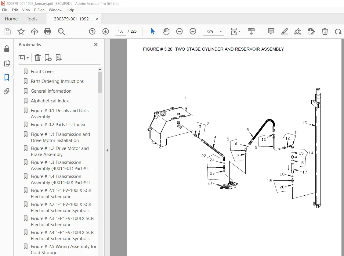
Figure # 3 20 Two Stage Cylinder and Reservoir Assembly 106
Figure # 3 21 Two Stage Cylinder Assembly (40534-XX) 108
Figure # 3 22 Three Stage Cylinder and Reservoir Assembly 110
Figure # 3 23 Three Stage Staging Cylinder Assembly (40891-XX) 112
Figure # 3 24 Three Stage Freelift Cylinder Assembly (40092-XX) 114
Figure # 4 1 Shielding Assembly 116
Figure # 4 2 Emergency Disconnect Assembly 118
Figure # 4 3 Auxiliary Control Assembly 120
Figure # 4 4 Hand Lift/Lower and Speed Control 122
Figure # 4 5 Steering Control Assembly 124
Figure # 4 6 Idler Wheel Installation 126
Figure # 4 7 Idler Wheel Assembly 128
Figure # 4 8 Main Frame and Load Wheel Assembly 130
Figure # 4 9 Single Load Wheel Assembly 132
Figure # 4 10 5″ High Articulating Load Wheel Assembly 134
Figure # 4 11 4″ High Articulating Load Wheel Assembly 136
Figure # 5 1 Two Stage Mast Installation 138
Figure # 5 2 Two Stage Inner Column Assembly 140
Figure # 5 3 Two Stage Outer Column Assembly 142
Figure # 5 4 Two Stage Cylinder Assembly 144
Figure # 5 5 Two Stage Single Reach Assembly 146
Figure # 5 6 Two Stage Single Reach Front Frame 148
Figure # 5 7 Two Stage Double Reach Assembly 150
Figure # 5 8 Two Stage Double Reach Front Frame 152
Figure # 5 9 Two Stage Sideshifter Assembly (40472-00) 154
Figure # 5 10 Two Stage Fork Assembly (25008-XX) 156
Figure # 5 11 Three Stage Mast Installation 158
Figure # 5 12 Three Stage Inner Column Assembly 160
Figure # 5 13 Three Stage Freelift Cylinder Installation 162
Figure # 5 14 Three Stage Intermediate Column Assembly 164
Figure # 5 15 Three Stage Outer Column Assembly 166
Figure # 5 16 Three Stage Single Reach Assembly 168
Figure # 5 17 Three Stage Single Reach Front Frame 170
Figure # 5 18 Three Stage Double Reach Assembly 172
Figure # 5 19 Three Stage Double Reach Front Frame 174
Figure # 5 20 Three Stage Sideshifter Assembly (40472-00) 176
Figure # 5 21 Three Stage Fork Assembly (25008-XX) 178
Figure # 6 1 Manlift EV-100 LX SCR Electrical Schematic 180
Figure # 6 2 Manlift EV-100 LX SCR Electrical Schematic Symbols 181
Figure # 6 3 Three Stage Fork Assembly (25008-XX) 182
Figure # 6 4 Manlift Three Stage Mast Cable Assembly 184
Figure # 6 5 Manlift Reach and Platform Cable Assembly 186
Figure # 6 6 Manlift Power Component Wiring 188
Figure # 6 7 Manlift Connector Assembly (49855-16) 190
Figure # 6 8 Manlift Hydraulic Schematic 192
Figure # 6 9 Manlift Hydraulic Schematic Symbols 193
Figure # 6 10 Manlift Hydraulic Diagram 194
Figure # 6 11 Manlift Valve Assembly (24 Volt, 41461-01) (36 Volt, 41461-00) 196
Figure # 6 12 Manlift Valve Assembly (24 Volt, 41460-01) (36 Volt, 41460-00) 198
Figure # 6 13 Manlift Load Backrest Installation 200
Figure # 10 1 Special Tools and Lubrications 202
Numerical Index 205
Back Cover 226
DESCRIPTION:
BT Prime-Mover RR-30C Electric Reach Truck Parts Manual – PDF DOWNLOAD
Manual Part Number 300379-001
S.V 31/01/2025