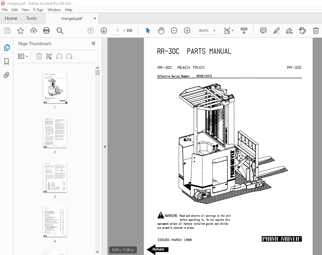
BT Prime-Mover RR-30C Reach Truck Parts Manual SN RR30C170373 PDF
$28.95
BT Prime-Mover RR-30C Reach Truck Parts Manual SN RR30C170373 – PDF DOWNLOAD
Description
BT Prime-Mover RR-30C Reach Truck Parts Manual SN RR30C170373 – PDF DOWNLOAD
FILE DETAILS:
BT Prime-Mover RR-30C Reach Truck Parts Manual SN RR30C170373 – PDF DOWNLOAD
Language : English
Pages : 938
Downloadable : Yes
File Type : PDF
IMAGES PREVIEW OF THE MANUAL:
TABLE OF CONTENTS:
BT Prime-Mover RR-30C Reach Truck Parts Manual SN RR30C170373 – PDF DOWNLOAD
Front Cover 1
Parts Ordering Instructions 2
General Information 3
Alphabetical Index 4
Figure # 1 Decal and Parts Assembly 6
Figure # 2 Parts List and Service Reference Index 8
Figure # 3 Shielding Assembly 10
Figure # 4 Emergency Disconnect Assembly 12
Figure # 5 Auxiliary Control Assembly 14
Figure # 6 Hand Lift/Lower and Speed Control 16
Figure # 7 Master Control Switch 18
Figure # 8 Steering Assembly 20
Figure # 9 Torque Generator Assembly 22
Figure # 10 Auxiliary Pump and Motor Assembly 24
Figure # 11 Auxiliary Pump Assembly 26
Figure # 12 Auxiliary Motor Assembly 28
Figure # 13 Transmission and Drive Motor Installation 30
Figure # 14 Brake Assembly 32
Figure # 15 Drive Motor Assembly 34
Figure # 16 Transmission Assembly Part # 1 36
Figure # 17 Transmission Assembly Part # 2 38
Figure # 18 EV-100 Electrical Schematic 40
Figure # 19 Electrical Schematic Symbols 41
Figure # 20 Wiring Assembly for Cold Storage 42
Figure # 21 Wiring Harness Assembly 44
Figure # 22 Limit Switch Wiring Harness Assembly 46
Figure # 23 Two Stage Mast Cable Assembly 48
Figure # 24 Three Stage Mast Cable Assembly 50
Figure # 25 Single Reach Cable Assembly 52
Figure # 26 Power Component Wiring 54
Figure # 27 EV-100 SCR Contactor Panel Assembly 56
Figure # 28 EV-100 SCR Control 58
Figure # 29 EV-100 Forward & Rearward Contactor Assembly 60
Figure # 30 EV-100 Lift Pump(s) and 1A Contactor Assembly 62
Figure # 31 EV-100 Steering Contactor Assembly 64
Figure # 32 Connector Assembly 66
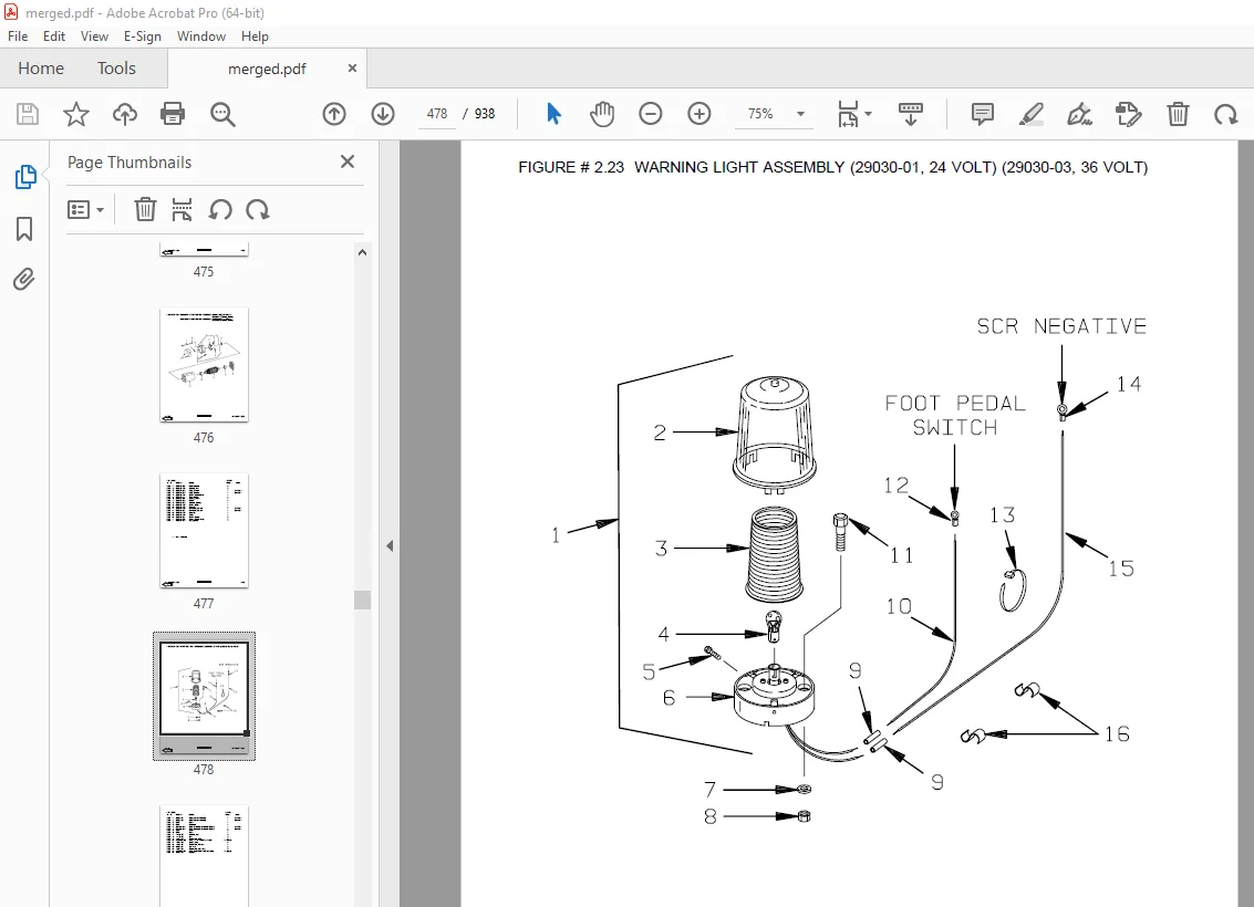
Figure # 33 Warning Light Assembly 68
Figure # 34 Hydraulic Schematic 70
Figure # 35 Hydraulic Schematic Symbols 71
Figure # 36 Auxiliary Pump and Reservoir Assembly 72
Figure # 37 Auxiliary Control Valve Assembly 74
Figure # 38 Hydraulic Reservoir Assembly 76
Figure # 39 Two Stage Mast Hydraulic Assembly 78
Figure # 40 Three Stage Mast Hydraulic Assembly 80
Figure # 41 Single Reach, Reach Cylinder Hose Installation 82
Figure # 42 Single Reach Diverter Valve Assembly 84
Figure # 43 Single Reach, Reach Cylinder Assembly 86
Figure # 44 Single Reach, Tilt and Sideshift Hose Installation 88
Figure # 45 Tilt Cylinder Assembly 90
Figure # 46 Sideshifter Cylinder Assembly 92
Figure # 47 Lift Pump and Reservoir Assembly 94
Figure # 48 Lift Pump and Motor Assembly 96
Figure # 48 1 Lift Pump and Motor Assembly 98
Figure # 49 24 Volt Lift Pump Assembly 100
Figure # 50 36 Volt Lift Pump Assembly 102
Figure # 51 Lift Motor Assembly 104
Figure # 52 Lift Control Valve Assembly 106
Figure # 53 Two Stage Cylinder and Reservoir Assembly 108
Figure # 54 Two Stage Cylinder Assembly 110
Figure # 55 Three Stage Cylinder and Reservoir Assembly 112
Figure # 56 Three Stage Staging Cylinder Assembly 114
Figure # 57 Three Stage Freelift Cylinder Assembly 116
Figure # 58 Two Stage Mast Installation 118
Figure # 59 Two Stage Inner Column Assembly 120
Figure # 60 Two Stage Outer Column Assembly 122
Figure # 61 Two Stage Cylinder Installation 124
Figure # 62 Single Reach Assembly 126
Figure # 63 Single Reach with Tilt Front Frame 128
Figure # 64 Sideshifter Assembly 130
Figure # 65 Fork Assembly 132
Figure # 66 Three Stage Mast Installation 134
Figure # 67 Three Stage Outer Column Assembly 136
Figure # 68 Three Stage Intermediate Column Assembly 138
Figure # 69 Three Stage Inner Column Assembly 140
Figure # 70 Three Stage Freelift Cylinder Installation 142
Figure # 71 Main Frame and Load Wheel Assembly 144
Figure # 72 Single Load Wheel Assembly 146
Figure # 73 5″ High Articulating Load Wheel Assembly 148
Figure # 74 4″ High Articulating Load Wheel Assembly 150
Figure # 75 Caster Assembly 152
Figure # 76 Special Tools and Lubrications 154
Numerical Index 156
Appendix 1 for EV-1 SCR Electrical System 171
Figure # 1 EV-1 Electrical Schematic 172
Figure # 2 Electrical Schematic Symbols 173
Figure # 3 EV-1 Power Component Wiring 174
Figure # 4 EV-1 SCR and Contactor Panel Assembly 176
Figure # 5 EV-1 SCR Control 178
Figure # 6 EV-1 Transformer Assembly 180
Figure # 7 EV-1 Rectifier Heat Sink Assembly 182
Figure # 8 EV-1 Lift Pump and 1A Contactor Assembly 184
Figure # 9 EV-1 Steering Contactor Assembly 186
Figure # 10 EV-1 Forward and Rearward Contactor Assembly 188
Back Cover 190
Front Cover 191
Parts Ordering Instructions 192
General Information 193
Alphabetical Index 194
Figure # 0 1 Decals and Parts Assembly 198
Figure # 0 2 Parts List Index 200
Figure # 1 1 Transmission and Drive Motor Installation 204
Figure # 1 2 Drive Motor and Brake Assembly 206
Figure # 1 3 Transmission Assembly 208
Figure # 1 4 Transmission Assembly 210
Figure # 2 1 “E” EV-100LX SCR Electrical Schematic 212
Figure # 2 2 EV-100LX SCR Electrical Schematic Symbols 213
Figure # 2 3 “EE” EV-100LX SCR Electrical Schematic 214
Figure # 2 4 “EE” EV-100LX SCR Electrical Schematic Symbols 215
Figure # 2 5 Wiring Assembly for Cold Storage 216
Figure # 2 6 Wiring Harness Assembly 218
Figure # 2 7 Limit Switch Wiring Assembly 220
Figure # 2 8 Two Stage Mast Cable Assembly 222
Figure # 2 9 Three Stage Mast Cable Assembly 224
Figure # 2 10 Reach Cable Assembly 226
Figure # 2 11 EV-100LX Power Component Wiring 228
Figure # 2 12 EV-100LX TX and TT SCR Control Panel Assembly 230
Figure # 2 13 EV-100LX Contactor Panel Assembly & Related Parts for “E” and “EE” 232
Figure # 2 14 EV-100LX Contactor Panel Assembly 234
Figure # 2 15 EV-100LX SCR Forward & Rearward Contactor Assembly 236
Figure # 2 16 EV-100LX SCR 1A Contactor Assembly 238
Figure # 2 17 Lift Pump Contactor Assembly 240
Figure # 2 18 EV-100LX SCR Auxiliary Pump Contactor Assembly 242
Figure # 2 19 Power Connector Assembly 244
Figure # 2 20 Lift Pump Motor Assembly 246
Figure # 2 21 Drive Motor Assembly 248
Figure # 2 22 Auxiliary Pump Motor Assembly 250
Figure # 2 23 Warning Light Assembly 252
Figure # 2 24 “E” EV-100LX TT SCR Electrical Schematic 254
Figure # 2 25 “E” EV-100LX TT SCR Electrical Schematic Symbols 255
Figure # 2 26 “EE” EV-100LX TT SCR Electrical Schematic 256
Figure # 2 27 “EE” EV-100LX TT SCR Electrical Schematic Symbols 257
Figure # 2 28 EV-100LX Dash Display Installation 258
Figure # 3 1 Hydraulic Schematic 260
Figure # 3 2 Hydraulic Schematic Symbols 261
Figure # 3 3 Auxiliary Pump and Reservoir Assembly 262
Figure # 3 4 Auxiliary Control Valve Assembly 264
Figure # 3 5 Auxiliary Pump and Motor Assembly 266
Figure # 3 6 Auxiliary Pump Assembly 268
Figure # 3 7 Hydraulic Reservoir Assembly 270
Figure # 3 8 Torque Generator Assembly 272
Figure # 3 9 Two Stage Mast Hydraulic Assembly 274
Figure # 3 10 Three Stage Mast Hydraulic Assembly 276
Figure # 3 11 Reach Cylinder Hose Installation 278
Figure # 3 12 Reach Diverter Valve Assembly 280
Figure # 3 13 Reach Cylinder Assembly 282
Figure # 3 14 Tilt and Sideshift Hose Installation 284
Figure # 3 15 Tilt Cylinder Assembly 286
Figure # 3 16 Lift Pump and Reservoir Assembly 288
Figure # 3 17 Lift Pump Motor Assembly 290
Figure # 3 18 Lift Pump Motor Assembly, 24 Volt 292
Figure # 3 19 Lift Pump Motor Assembly, 36 Volt 294
Figure # 3 20 Lift Control Valve Assembly 296
Figure # 3 21 Two Stage Cylinder and Reservoir Assembly 298
Figure # 3 22 Two Stage Cylinder Assembly 300
Figure # 3 24 Three Stage Staging Cylinder Assembly 304
Figure # 3 25 Three Stage Freelift Cylinder Assembly 306
Figure # 4 1 Shielding Assembly 308
Figure # 4 2 Emergency Disconnect Assembly 310
Figure # 4 3 Auxiliary Control Assembly 312
Figure # 4 4 Hand Lift/Lower and Speed Control 314
Figure # 4 5 Forward Steering Control Assembly 316
Figure # 4 6 Rearward Steering Control Assembly 318
Figure # 4 7 Auxiliary Pump and Motor Installation 320
Figure # 4 8 Main Frame and Load Wheel Assembly 322
Figure # 4 9 Single Load Wheel Assembly 324
Figure # 4 10 5″ High Articulating Load Wheel Assembly 326
Figure # 4 11 4″ High Articulating Load Wheel Assembly 328
Figure # 4 12 Caster Assembly 330
Figure # 5 1 Two Stage Mast Installation 332
Figure # 5 2 Two Stage Inner Column Assembly 334
Figure # 5 3 Two Stage Outer Column Assembly 336
Figure # 5 4 Two Stage Cylinder Assembly 338
Figure # 5 5 Two Stage Reach Assembly 340
Figure # 5 6 Two Stage Reach Front Frame 342
Figure # 5 7 Two Stage Sideshifter Assembly 344
Figure # 5 8 Two Stage Fork Assembly 346
Figure # 5 9 Three Stage Mast Installation 348
Figure # 5 10 Three Stage Inner Column Assembly 350
Figure # 5 11 Three Stage Freelift Cylinder Installation 352
Figure # 5 12 Three Stage Intermediate Column Assembly 354
Figure # 5 13 Three Stage Outer Column Assembly 356
Figure # 5 14 Three Stage Reach Assembly 358
Figure # 5 15 Three Stage Reach Front Frame 360
Figure # 5 16 Three Stage Sideshifter Assembly 362
Figure # 5 17 Three Stage Fork Assembly 364
Figure # 6 1 Manlift EV-100 LX SCR Electrical Schematic 366
Figure # 6 2 Manlift EV-100 LX SCR Electrical Schematic Symbols 367
Figure # 6 3 Three Stage Fork Assembly 368
Figure # 6 4 Manlift Three Stage Mast Cable Assembly 370
Figure # 6 5 Manlift Reach and Platform Cable Assembly 372
Figure # 6 6 Manlift Power Component Wiring 374
Figure # 6 7 Manlift Connector Assembly 376
Figure # 6 8 Manlift Hydraulic Schematic 378
Figure # 6 9 Manlift Hydraulic Schematic Symbols 379
Figure # 6 10 Manlift Hydraulic Diagram 380
Figure # 6 11 Block Manlift Valve Assembly 382
Figure # 6 12 Manlift Valve Assembly 384
Figure # 6 13 Manlift Load Backrest Installation 386
Figure # 7 1 Battery Lift Interrupt “E” EV-100LX SCR Electrical Schematic 388
Figure # 7 2 Battery Lift Interrupt “E” EV-100LX SCR Electrical Schematic Symbols 389
Figure # 7 3 Battery Lift Interrupt “EE” EV-100LX SCR Electrical Schematic 390
Figure # 7 4 Battery Lift Interrupt “EE” EV-100LX SCR Electrical Schematic Symbols 391
Figure # 7 5 Battery Lift Interrupt Installation 392
Figure # 10 1 Special Tools and Lubrications 394
Numerical Index 397
Back Cover 416
Front Cover 417
Parts Ordering Instructions 418
General Information 419
Alphabetical Index 420
Figure # 0 1 Decals and Parts Assembly 424
Figure # 0 2 Parts List Index 426
Figure # 1 1 Transmission and Drive Motor Installation 430
Figure # 1 2 Drive Motor and Brake Assembly 432
Figure # 1 3 Transmission Assembly 434
Figure # 1 4 Transmission Assembly 436
Figure # 2 1 “E” EV-100LX SCR Electrical Schematic 438
Figure # 2 2 “E” EV-100LX SCR Electrical Schematic Symbols 439
Figure # 2 3 “EE” EV-100LX SCR Electrical Schematic 440
Figure # 2 4 “EE” EV-100LX SCR Electrical Schematic Symbols 441
Figure # 2 5 Wiring Assembly for Cold Storage 442
Figure # 2 6 Wiring Harness Assembly 444
Figure # 2 7 Limit Switch Wiring Assembly 446
Figure # 2 8 Two Stage Mast Cable Assembly 448
Figure # 2 9 Three Stage Mast Cable Assembly 450
Figure # 2 10 Reach Cable Assembly 452
Figure # 2 11 EV-100LX Power Component Wiring 454
Figure # 2 12 EV-100LX TX & TT SCR Control Panel Assembly 456
Figure # 2 13 EV-100LX Contactor Panel Assembly & Related Parts for “E” and “EE” 458
Figure # 2 14 EV-100LX Contactor Panel Assembly 460
Figure # 2 15 EV-100LX SCR Forward & Rearward Contactor Assembly 462
Figure # 2 16 EV-100LX SCR 1A Contactor Assembly 464
Figure # 2 17 Lift Pump Contactor Assembly 466
Figure # 2 18 EV-100LX SCR Auxiliary Pump Contactor Assembly 468
Figure # 2 19 Power Connector Assembly 470
Figure # 2 20 Lift Pump Motor Assembly, 24 & 36 Volt 472
Figure # 2 21 Drive Motor Assembly, 24 & 36 Volt 474
Figure # 2 22 Auxiliary Pump Motor Assembly 476
Figure # 2 23 Warning Light Assembly 478
Figure # 2 24 “E” EV-100LX TT SCR Electrical Schematic 480
Figure # 2 25 “E” EV-100LX TT SCR Electrical Schematic Symbols 481
Figure # 2 26 “EE” EV-100LX TT SCR Electrical Schematic 482
Figure # 2 27 “EE” EV-100LX TT SCR Electrical Schematic Symbols 483
Figure # 2 28 EV-100LX Dash Display Installation 484
Figure # 3 1 Hydraulic Schematic 486
Figure # 3 2 Hydraulic Schematic Symbols 487
Figure # 3 3 Auxiliary Pump and Reservoir Assembly 488
Figure # 3 4 Auxiliary Control Valve Assembly 490
Figure # 3 5 Auxiliary Pump and Motor Assembly 492
Figure # 3 6 Auxiliary Pump Assembly 494
Figure # 3 7 Hydraulic Reservoir Assembly 496
Figure # 3 8 Torque Generator Assembly 498
Figure # 3 9 Two Stage Mast Hydraulic Assembly 500
Figure # 3 10 Three Stage Mast Hydraulic Assembly 502
Figure # 3 11 Reach Cylinder Hose Installation 504
Figure # 3 12 Reach Diverter Valve Assembly 506
Figure # 3 13 Reach Cylinder Assembly 508
Figure # 3 14 Tilt and Sideshift Hose Installation 510
Figure # 3 15 Tilt Cylinder Assembly 512
Figure # 3 16 Lift Pump and Reservoir Assembly 514
Figure # 3 17 Lift Pump Motor Assembly 516
Figure # 3 18 Lift Pump Motor Assembly, 24 Volt 518
Figure # 3 19 Lift Pump Motor Assembly, 36 Volt 520
Figure # 3 20 Lift Control Valve Assembly 522
Figure # 3 21 Two Stage Cylinder and Reservoir Assembly 524
Figure # 3 22 Two Stage Cylinder Assembly 526
Figure # 3 23 Three Stage Cylinder and Reservoir Assembly 528
Figure # 3 24 Three Stage Staging Cylinder Assembly 530
Figure # 3 25 Three Stage Freelift Cylinder Assembly 532
Figure # 4 1 Shielding Assembly 534
Figure # 4 2 Emergency Disconnect Assembly 536
Figure # 4 3 Auxiliary Control Assembly 538
Figure # 4 4 Hand Lift/Lower and Speed Control 540
Figure # 4 5 Forward Steering Control Assembly 542
Figure # 4 6 Rearward Steering Control Assembly 544
Figure # 4 7 Auxiliary Pump and Motor Installation 546
Figure # 4 8 Main Frame and Load Wheel Assembly 548
Figure # 4 9 Single Load Wheel Assembly 550
Figure # 4 10 5″ High Articulating Load Wheel Assembly 552
Figure # 4 11 4″ High Articulating Load Wheel Assembly 554
Figure # 4 12 Caster Assembly 556
Figure # 4 13 Hand Lift/Lower and Speed Control for 3 Function Control 558
Figure # 5 1 Two Stage Mast Installation 560
Figure # 5 2 Two Stage Inner Column Assembly 562
Figure # 5 3 Two Stage Outer Column Assembly 564
Figure # 5 4 Two Stage Cylinder Assembly 566
Figure # 5 5 Two Stage Reach Assembly 568
Figure # 5 6 Two Stage Reach Front Frame 570
Figure # 5 7 Two Stage Sideshifter Assembly 572
Figure # 5 8 Two Stage Fork Assembly 574
Figure # 5 9 Three Stage Mast Installation 576
Figure # 5 10 Three Stage Inner Column Assembly 578
Figure # 5 11 Three Stage Freelift Cylinder Installation 580
Figure # 5 12 Three Stage Intermediate Column Assembly 582
Figure # 5 13 Three Stage Outer Column Assembly 584
Figure # 5 14 Three Stage Reach Assembly 586
Figure # 5 15 Three Stage Reach Front Frame 588
Figure # 5 16 Three Stage Sideshifter Assembly 590
Figure # 5 17 Three Stage Fork Assembly 592
Figure # 6 1 Manlift EV-100 LX SCR Electrical Schematic 594
Figure # 6 2 Manlift EV-100 LX SCR Electrical Schematic Symbols 595
Figure # 6 3 Three Stage Fork Assembly 596
Figure # 6 4 Manlift Three Stage Mast Cable Assembly 598
Figure # 6 5 Manlift Reach and Platform Cable Assembly 600
Figure # 6 6 Manlift Power Component Wiring 602
Figure # 6 7 Manlift Connector Assembly 604
Figure # 6 8 Manlift Hydraulic Schematic 606
Figure # 6 9 Manlift Hydraulic Schematic Symbols 607
Figure # 6 10 Manlift Hydraulic Diagram 608
Figure # 6 11 Block Manlift Valve Assembly, 24 & 36 Volt 610
Figure # 6 12 Manlift Valve Assembly, 24 & 36 Volt 612
Figure # 6 13 Manlift Load Backrest Installation 614
Figure # 7 1 Battery Lift Interrupt “E” EV-100LX SCR Electrical Schematic 616
Figure # 7 2 Battery Lift Interrupt “E” EV-100LX SCR Electrical Schematic Symbols 617
Figure # 7 3 Battery Lift Interrupt “EE” EV-100LX SCR Electrical Schematic 618
Figure # 7 4 Battery Lift Interrupt “EE” EV-100LX SCR Electrical Schematic Symbols 619
Figure # 7 5 Battery Lift Interrupt Installation 620
Figure # 10 1 Special Tools and Lubrications 622
Numerical Index 625
Back Cover 644
Front Cover 645
Parts Ordering Instructions 646
Field Modifications 646
General Information 647
Alphabetical Index 648
Section 0 0 652
Figure # 0 1 Decals and Parts Assembly 652
Section 1 0 654
Figure # 1 1 Transmission and Drive Motor Installation 654
Figure # 1 2 Drive Motor and Brake Assembly 656
Figure # 1 3 Transmission Assembly Part #1 658
Figure # 1 4 Transmission Assembly Part #2 660
Section 2 0 662
Figure # 2 1 “E” EV-100LX SCR Electrical Schematic 662
Figure # 2 2 “E” EV-100LX SCR Electrical Schematic Symbols 663
Figure # 2 3 “EE” EV-100LX SCR Electrical Schematic 664
Figure # 2 4 “EE” EV-100LX SCR Electrical Schematic Symbols 665
Figure # 2 5 Wiring Assembly for Cold Storage 666
Figure # 2 6 Wiring Harness Assembly 668
Figure # 2 7 Limit Switch Wiring Assembly 670
Figure # 2 8 Two Stage Mast Cable Assembly 672
Figure # 2 9 Three Stage Mast Cable Assembly 674
Figure # 2 10 Reach Cable Assembly 676
Figure # 2 11 EV-100LX Power Component Wiring 678
Figure # 2 12 EV-100LX TX & TT SCR Control Panel Assembly 680
Figure # 2 13 EV-100LX Contactor Panel Assembly & Related Parts for “E” and “EE” 682
Figure # 2 14 EV-100LX Contactor Panel Assembly 684
Figure # 2 15 EV-100LX SCR Forward & Rearward Contactor Assembly 686
Figure # 2 16 EV-100LX SCR 1A Contactor Assembly 688
Figure # 2 17 Lift Pump Contactor Assembly 690
Figure # 2 18 EV-100LX SCR Auxiliary Pump Contactor Assembly 692
Figure # 2 19 Power Connector Assembly 694
Figure # 2 20 Lift Pump Motor Assembly 696
Figure # 2 21 Lift Pump Motor Assembly, 36 Volt 698
Figure # 2 22 Drive Motor Assembly 700
Figure # 2 23 Auxiliary Pump Motor Assembly 702
Figure # 2 24 Warning Light Assembly 704
Figure # 2 25 “E” EV-100LX TT SCR Electrical Schematic 706
Figure # 2 26 “E” EV-100LX TT SCR Electrical Schematic Symbols 707
Figure # 2 27 “EE” EV-100LX TT SCR Electrical Schematic 708
Figure # 2 28 “EE” EV-100LX TT SCR Electrical Schematic Symbols 709
Figure # 2 29 EV-100LX Dash Display Installation 710
Figure # 2 30 EV-100LX SCR Electrical Schematic – 3 Function Control Handle 712
Figure # 2 31 EV-100LX SCR Electrical Schematic Symbols 713
Figure # 2 30A TX EV-100LX Electrical Schematic – 3 Function Control Handle 714
Figure # 2 31A EV-100LX SCR Electrical Schematic Symbols 715
Figure # 2 30B TT EV-100LX Electrical Schematic – 3 Function Control Handle 716
Figure # 2 31B EV-100LX SCR Electrical Schematic Symbols 717
Figure # 2 32 Wiring Harness Assembly for 3 Function Control Valve 718
Section 3 0 720
Figure # 3 1 Hydraulic Schematic 720
Figure # 3 2 Hydraulic Schematic Symbols 721
Figure # 3 3 Auxiliary Pump and Reservoir Assembly 722
Figure # 3 4 Auxiliary Control Valve Assembly 724
Figure # 3 5 Auxiliary Pump and Motor Assembly 726
Figure # 3 6 Auxiliary Pump Assembly 728
Figure # 3 7 Hydraulic Reservoir Assembly 730
Figure # 3 8 Torque Generator Assembly 732
Figure # 3 9 Two Stage Mast Hydraulic Assembly 734
Figure # 3 10 Three Stage Mast Hydraulic Assembly 736
Figure # 3 11 Reach Cylinder Hose Installation 738
Figure # 3 12 Reach Diverter Valve Assembly 740
Figure # 3 13 Reach Cylinder Assembly 742
Figure # 3 14 Tilt and Sideshift Hose Installation 744
Figure # 3 15 Tilt Cylinder Assembly 746
Figure # 3 16 Lift Pump and Reservoir Assembly 748
Figure # 3 17 Lift Pump Motor Assembly 750
Figure # 3 18 Lift Pump Assembly 752
Figure # 3 19 Lift Pump Motor Assembly, 36 Volt 754
Figure # 3 20 Lift Control Valve Assembly 756
Figure # 3 21 Two Stage Cylinder and Reservoir Assembly 758
Figure # 3 22 Two Stage Cylinder Assembly 760
Figure # 3 23 Three Stage Cylinder and Reservoir Assembly 762
Figure # 3 24 Three Stage Staging Cylinder Assembly 764
Figure # 3 25 Three Stage Freelift Cylinder Assembly 766
Figure # 3 26 Hydraulic Schematic for 3 Function Control Handle 768
Figure # 3 27 Hydraulic Schematic Symbols 769
Figure # 3 28 Auxiliary Pump & Reservoir Assembly for 3 Function Control Handle 770
Figure # 3 29 Valve Assembly 772
Figure # 3 30 Two Stage Mast Hydraulic Assembly for 3 Function Control Handle 774
Figure # 3 31 Three Stage Mast Hydraulic Assembly for 3 Function Control Handle 776
Section 4 0 778
Figure # 4 1 Shielding Assembly 778
Figure # 4 2 Emergency Disconnect Assembly 780
Figure # 4 3 Auxiliary Control Assembly 782
Figure # 4 4 Hand Lift/Lower and Speed Control 784
Figure # 4 5 Forward Steering Control Assembly 786
Figure # 4 6 Rearward Steering Control Assembly 788
Figure # 4 7 Auxiliary Pump and Motor Installation 790
Figure # 4 8 Main Frame and Load Wheel Assembly 792
Figure # 4 9 Single Load Wheel Assembly 794
Figure # 4 9A Single Load Wheel Assembly 796
Figure # 4 10 5″ High Articulating Load Wheel Assembly 798
Figure # 4 10A 5″ High Articulating Load Wheel Assembly 800
Figure # 4 11 4″ High Articulating Load Wheel Assembly 802
Figure # 4 11A 4″ High Articulating Load Wheel Assembly 804
Figure # 4 12 Caster Assembly 806
Figure # 4 13 Hand Lift/Lower and Speed Control for 3 Function Control 808
Section 5 0 810
Figure # 5 1 Two Stage Mast Installation 810
Figure # 5 2 Two Stage Inner Column Assembly 812
Figure # 5 3 Two Stage Outer Column Assembly 814
Figure # 5 4 Two Stage Cylinder Assembly 816
Figure # 5 5 Two Stage Reach Assembly 818
Figure # 5 6 Two Stage Reach Front Frame 820
Figure # 5 7 Two Stage Sideshifter Assembly 822
Figure # 5 8 Two Stage Fork Assembly 824
Figure # 5 9 Three Stage Mast Installation 826
Figure # 5 10 Three Stage Inner Column Assembly 828
Figure # 5 11 Three Stage Freelift Cylinder Installation 830
Figure # 5 12 Three Stage Intermediate Column Assembly 832
Figure # 5 13 Three Stage Outer Column Assembly 834
Figure # 5 14 Three Stage Reach Assembly 836
Figure # 5 15 Three Stage Reach Front Frame 838
Figure # 5 16 Three Stage Sideshifter Assembly 840
Figure # 5 17 Three Stage Fork Assembly 842
Section 6 0 844
Figure # 6 1 Remote Lift/Lower EV-100 LX SCR Electrical Schematic 844
Figure # 6 2 Remote Lift/Lower EV-100 LX SCR Electrical Schematic Symbols 845
Figure # 6 3 Remote Lift/Lower Wiring Harness Assembly 846
Figure # 6 4 Remote Lift/Lower Three Stage Mast Cable Assembly 848
Figure # 6 5 Remote Lift/Lower Reach and Platform Cable Assembly 850
Figure # 6 6 Remote Lift/Lower Power Component Wiring 852
Figure # 6 7 Remote Lift/Lower Connector Assembly 854
Figure # 6 8 Remote Lift/Lower Hydraulic Schematic 856
Figure # 6 9 Remote Lift/Lower Manlift Hydraulic Schematic Symbols 857
Figure # 6 10 Remote Lift/Lower Hydraulic Diagram 858
Figure # 6 11 Blocking Remote Lift/Lower Valve Assembly 860
Figure # 6 12 Remote Lift/Lower Valve Assembly 862
Figure # 6 13 Remote Lift/Lower Load Backrest Installation 864
Figure # 6 14 Remote Lift/Lower Contactor Assembly 866
Section 7 0 868
Figure # 7 1 Battery Lift Interrupt “E” EV-100LX SCR Electrical Schematic 868
Figure # 7 2 Battery Lift Interrupt “E” EV-100LX SCR Electrical Schematic Symbols 869
Figure # 7 3 Battery Lift Interrupt “EE” EV-100LX SCR Electrical Schematic 870
Figure # 7 4 Battery Lift Interrupt “EE” EV-100LX SCR Electrical Schematic Symbols 871
Figure # 7 5 Battery Lift Interrupt Installation 872
Section 10 0 874
Figure # 10 1 Special Tools and Lubrications 874
Numerical Index 877
Back Cover 898
Front Cover 899
Figure # I RR-30C “E” EV-100 LX SCR Electrical Schematic 900
Figure # II RR-30C “E” EV-100LX SCR Electrical Schematic Symbols 901
Figure # III RR-30C “EE” EV-100LX SCR Electrical Schematic 902
Figure # IV RR-30C “EE” Electrical Schematic Symbols 903
Figure # V EV-100LX Wiring Assembly for Cold Storage 904
Figure # VII EV-100LX Limit Switch Wiring Harness Assembly 906
Figure # VIII EV-100LX Two Stage Mast Cable Assembly 908
Figure # IX EV-100LX Three Stage Mast Cable Assembly 910
Figure # X EV-100LX Single Reach Cable Assembly 912
Figure # XI EV-100LX Power Component Wiring 914
Figure # XII EV-100LX SCR Control Panel 916
Figure # XIII EV-100LX Contactor Panel Assembly & Related Parts for “E” and “EE” 918
Figure # XIV EV-100LX Contactor Panel Assembly (24 & 36 Volt) 920
Figure # XV EV-100LX Forward & Rearward Contactor Assembly 922
Figure # XVI EV-100LX 1A Contactor Assembly 924
Figure # XVII EV-100 SCR Lift Pump Contactor Assembly (24 & 36 Volt) 926
Figure # XVIII EV-100LX Auxiliary Pump Contactor Assembly 928
Figure # XIX EV-100LX Power Connector Assembly 930
Figure # XX 24 & 36 Volt Pump Motor Assembly 932
Figure # XXI 24 & 36 Volt Drive Motor Assembly 934
Figure # XXII Ohio Pump Motor Assembly 936
Back Cover 938
DESCRIPTION:
BT Prime-Mover RR-30C Reach Truck Parts Manual SN RR30C170373 – PDF DOWNLOAD
PARTS ORDERING INSTRUCTIONS:
HOW TO ORDER:
- When you order, supply the part number, quantity, model and serial numbers of your machine. Supplying this information will assure prompt, efficient handling of your order. The pictorial reference number is not needed and including it can only add confusion.
- Since your dealer carries many parts in stock and maintains up-to-date prices on all parts, he will be able to process your order immediately. If, for some reason, the part is not in stock, he will order it from the factory. In either event, he maintains a current file of service manuals, which give all available parts ordering or technical information.
- All prices are FOB factory in Muscatine, Iowa. Shipping charges are added to the price of the part shipping from the factory.
WHERE TO ORDER:
Always order parts from the dealer who sold you your Prime-Mover. If it is necessary for the dealer to order parts from the factory, he is able to get prompt service for you. Parts are shipped in accordance with shipping instructions given on the order.
S.V 31/01/2025