BT Prime Mover RR-34B Reach Truck Parts Manual – PDF DOWNLOAD
$34.95
BT Prime Mover RR-34B Reach Truck Parts Manual – PDF DOWNLOAD
Description
BT Prime Mover RR-34B Reach Truck Parts Manual – PDF DOWNLOAD
FILE DETAILS:
BT Prime Mover RR-34B Reach Truck Parts Manual – PDF DOWNLOAD
Language : English
Pages : 919
Downloadable : Yes
File Type : PDF
IMAGES PREVIEW OF THE MANUAL:
TABLE OF CONTENTS:
BT Prime Mover RR-34B Reach Truck Parts Manual – PDF DOWNLOAD
Front Cover 1
Parts Ordering Instructions 2
Field Modifications 2
General Information 3
Alphabetical Index 4
Figure # 1 Decal and Parts Assembly 6
Figure # 2 Parts List and Service Reference Index 8
Figure # 3 Shielding Assembly 10
Figure # 4 Emergency Disconnect Assembly 12
Figure # 5 Auxiliary Control Assembly 14
Figure # 6 Hand Lift/Lower and Speed Control 16
Figure # 7 Master Control Switch 18
Figure # 8 Steering Assembly 20
Figure # 9 Torque Generator Assembly 22
Figure # 10 Auxiliary Pump and Motor Assembly 24
Figure # 11 Auxiliary Pump Assembly 26
Figure # 12 Auxiliary Motor Assembly 28
Figure # 13 Transmission and Drive Motor Installation 30
Figure # 14 Brake Assembly 32
Figure # 15 Drive Motor Assembly 34
Figure # 16 Transmission Assembly Part # 1 36
Figure # 17 Transmission Assembly Part # 2 38
Figure # 18 EV-100 Electrical Schematic 40
Figure # 19 Electrical Schematic Symbols 41
Figure # 20 Wiring Assembly for Cold Storage 42
Figure # 21 Wiring Harness Assembly 44
Figure # 22 Limit Switch Wiring Harness Assembly 46
Figure # 23 Two Stage Mast Cable Assembly 48
Figure # 24 Three Stage Mast Cable Assembly 50
Figure # 25 Single Reach Cable Assembly 52
Figure # 26 Double Reach Cable Assembly 54
Figure # 27 Power Component Wiring 56
Figure # 28 EV-100 SCR Contactor Panel Assembly 58
Figure # 29 EV-100 SCR Control 60
Figure # 30 EV-100 Forward & Rearward Contactor Assembly 62
Figure # 31 EV-100 Lift Pump and 1A Contactor Assembly 64
Figure # 32 EV-100 Steering Contactor Assembly 66
Figure # 33 Connector Assembly 68
Figure # 34 Warning Light Assembly 70
Figure # 35 Hydraulic Schematic 72
Figure # 36 Hydraulic Schematic Symbols 73
Figure # 37 Auxiliary Pump and Reservoir Assembly 74
Figure # 38 Auxiliary Control Valve Assembly 76
Figure # 39 Hydraulic Reservoir Assembly 78
Figure # 40 Two Stage Mast Hydraulic Assembly 80
Figure # 41 Three Stage Mast Hydraulic Assembly 82
Figure # 42 Single Reach, Reach Cylinder Hose Installation 84
Figure # 43 Single Reach Diverter Valve Assembly 86
Figure # 44 Single Reach, Reach Cylinder Assembly 88
Figure # 45 Single Reach, Tilt and Sideshift Hose Installation 90
Figure # 46 Tilt Cylinder Assembly 92
Figure # 47 Sideshifter Cylinder Assembly 94
Figure # 48 Double Reach with Tilt and Sideshifter 96
Figure # 49 Double Reach Diverter Valve Assembly 98
Figure # 50 Double Reach, Reach Cylinder Assembly 100
Figure # 51 Lift Pump and Reservoir Assembly 102
Figure # 52 Lift Pump and Motor Assembly 104
Figure # 52 1 Lift Pump and Motor Assembly 106
Figure # 53 24 Volt Lift Pump Assembly 108
Figure # 54 36 Volt Lift Pump Assembly 110
Figure # 55 Lift Motor Assembly 112
Figure # 56 Lift Control Valve Assembly 114
Figure # 57 Two Stage Cylinder and Reservoir Assembly 116
Figure # 58 Two Stage Cylinder Assembly 118
Figure # 59 Three Stage Cylinder and Reservoir Assembly 120
Figure # 60 Three Stage Staging Cylinder Assembly 122
Figure # 61 Three Stage Freelift Cylinder Assembly 124
Figure # 62 Two Stage Mast Installation 126
Figure # 63 Two Stage Inner Column Assembly 128
Figure # 64 Two Stage Outer Column Assembly 130
Figure # 65 Two Stage Cylinder Installation 132
Figure # 66 Single Reach Assembly 134
Figure # 67 Single Reach Front Frame 136
Figure # 68 Double Reach Assembly 138
Figure # 69 Double Reach Front Frame 140
Figure # 70 Sideshifter Assembly 142
Figure # 71 Fork Assembly 144
Figure # 72 Three Stage Mast Installation 146
Figure # 73 Three Stage Outer Column Assembly 148
Figure # 74 Three Stage Intermediate Column Assembly 150
Figure # 75 Three Stage Inner Column Assembly 152
Figure # 76 Three Stage Freelift Cylinder Installation 154
Figure # 77 Main Frame and Load Wheel Assembly 156
Figure # 78 Single Load Wheel Assembly 158
Figure # 79 5″ High Articulating Load Wheel Assembly 160
Figure # 80 4″ High Articulating Load Wheel Assembly 162
Figure # 81 Caster Assembly 164
Figure # 82 Special Tools and Lubrications 166
Numerical Index 168
Appendix 1 187
Figure # 1 EV-1 Electrical Schematic 188
Figure # 2 Electrical Schematic Symbols 189
Figure # 3 EV-1 Power Component Wiring 190
Figure # 4 EV-1 SCR and Contactor Panel Assembly 192
Figure # 5 EV-1 SCR Control 194
Figure # 6 EV-1 Transformer Assembly 196
Figure # 7 EV-1 Rectifier Heat Sink Assembly 198
Figure # 8 EV-1 Lift Pump and 1A Contactor Assembly 200
Figure # 9 EV-1 Steering Contactor Assembly 202
Figure # 10 Forward and Rearward Contactor Assembly 204
Front Cover 206
Parts Ordering Instructions 207
General Information 208
Alphabetical Index 209
Figure # 0 1 Decals and Parts Assembly 213
Figure # 0 2 Parts List Index 215
Figure # 1 1 Transmission and Drive Motor Installation 219
Figure # 1 2 Drive Motor and Brake Assembly 221
Figure # 1 3 Transmission Assembly (40011-01) Part # I) 223
Figure # 1 4 Transmission Assembly (40011-00) Part # II) 225
Figure # 2 1 “E” EV-100LX SCR Electrical Schematic 227
Figure # 2 2 “E” EV-100LX SCR Electrical Schematic Symbols 228
Figure # 2 3 “EE” EV-100LX SCR Electrical Schematic 229
Figure # 2 4 “EE” EV-100LX SCR Electrical Schematic Symbols 230
Figure # 2 5 Wiring Assembly for Cold Storage 231
Figure # 2 6 Wiring Harness Assembly 233
Figure # 2 7 Limit Switch Wiring Assembly 235
Figure # 2 8 Two Stage Mast Cable Assembly 237
Figure # 2 9 Three Stage Mast Cable Assembly 239
Figure # 2 10 Single Reach Cable Assembly 241
Figure # 2 11 Double Reach Cable Assembly 243
Figure # 2 12 EV-100LX Power Component Wiring 245
Figure # 2 13 EV-100LX TX SCR Control Panel Assembly (49399-00) & EV-100LX TT SCR Control Panel Assembly (49399-01) 247
Figure # 2 14 EV-100LX Contactor Panel Assembly & Related Parts for “E” and “EE” 249
Figure # 2 15 EV-100LX Contactor Panel Assembly (24 Volt, 41757-01) (36 Volt, 41757-02) 251
Figure # 2 16 EV-100LX SCR Forward & Rearward Contactor Assembly (27692-00) 253
Figure # 2 17 EV-100LX SCR 1A Contactor Assembly (27693-02) 255
Figure # 2 18 Lift Pump Contactor Assembly (24 Volt, 27693-02) (36 Volt, 202169) 257
Figure # 2 19 EV-100LX SCR Auxiliary Pump Contactor Assembly (300073-000) 259
Figure # 2 20 Power Connector Assembly (24 Volt, 49855-24) (36 Volt, 49855-22) 261
Figure # 2 21 Lift Pump Motor Assembly, 24 Volt (27900-00, 5BT1324B54) G E & Lift Pump Motor Assembly, 36 Volt (27899-00, 5B 263
Figure # 2 22 Drive Motor Assembly, 24 Volt (27901-00, 5BT1326B235) G E & Drive Motor Assembly, 36 Volt (27902-00, 5BT1326B2 265
Figure # 2 23 Auxiliary Pump Motor Assembly 267
Figure # 2 24 Warning Light Assembly 269
Figure # 2 25 “E” EV-100LX TT SCR Electrical Schematic 271
Figure # 2 26 “E” EV-100LX TT SCR Electrical Schematic Symbols 272
Figure # 2 27 “EE” EV-100LX TT SCR Electrical Schematic 273
Figure # 2 28 “EE” EV-100LX TT SCR Electrical Schematic Symbols 274
Figure # 2 29 EV-100LX Dash Display Installation 275
Figure # 3 1 Hydraulic Schematic 277
Figure # 3 2 Hydraulic Schematic Symbols 278
Figure # 3 3 Auxiliary Pump and Reservoir Assembly 279
Figure # 3 4 Auxiliary Control Valve Assembly 281
Figure # 3 5 Auxiliary Pump and Motor Assembly 283
Figure # 3 6 Auxiliary Pump Assembly 285
Figure # 3 7 Hydraulic Reservoir Assembly 287
Figure # 3 8 Torque Generator Assembly 289
Figure # 3 9 Two Stage Mast Hydraulic Assembly 291
Figure # 3 10 Three Stage Mast Hydraulic Assembly 293
Figure # 3 11 Single Reach Reach Cylinder Hose Installation 295
Figure # 3 12 Single Reach Diverter Valve Assembly 297
Figure # 3 13 Single Reach Reach Cylinder Assembly 299
Figure # 3 14 Single Reach, Tilt and Sideshift Hose Installation 301
Figure # 3 15 Single Reach Tilt Cylinder Assembly 303
Figure # 3 16 Double Reach with Tilt and Sideshifter 305
Figure # 3 17 Double Reach Diverter Valve Assembly 307
Figure # 3 18 Double Reach Reach Cylinder Assembly 309
Figure # 3 19 Double Reach Tilt Cylinder Assembly 311
Figure # 3 20 Lift Pump and Reservoir Assembly 313
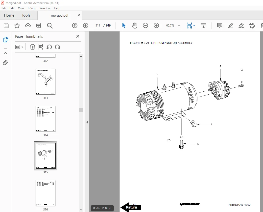
Figure # 3 21 Lift Pump Motor Assembly 315
Figure # 3 22 Lift Pump Motor Assembly, 24 Volt 317
Figure # 3 23 Lift Pump Motor Assembly, 36 Volt 319
Figure # 3 24 Lift Control Valve Assembly 321
Figure # 3 25 Two Stage Cylinder and Reservoir Assembly 323
Figure # 3 26 Two Stage Cylinder Assembly 325
Figure # 3 27 Three Stage Cylinder and Reservoir Assembly 327
Figure # 3 28 Three Stage Staging Cylinder Assembly 329
Figure # 3 29 Three Stage Freelift Cylinder Assembly 331
Figure # 4 1 Shielding Assembly 333
Figure # 4 2 Emergency Disconnect Assembly 335
Figure # 4 3 Auxiliary Control Assembly 337
Figure # 4 4 Hand Lift/Lower and Speed Control 339
Figure # 4 5 Forward Steering Control Assembly 341
Figure # 4 6 Rearward Steering Control Assembly 343
Figure # 4 7 Auxiliary Pump and Motor Installation 345
Figure # 4 8 Main Frame and Load Wheel Assembly 347
Figure # 4 9 Single Load Wheel Assembly 349
Figure # 4 10 5″ High Articulating Load Wheel Assembly 351
Figure # 4 11 4″ High Articulating Load Wheel Assembly 353
Figure # 4 12 Caster Assembly 355
Figure # 5 1 Two Stage Mast Installation 357
Figure # 5 2 Two Stage Inner Column Assembly 359
Figure # 5 3 Two Stage Outer Column Assembly 361
Figure # 5 4 Two Stage Cylinder Installation 363
Figure # 5 5 Two Stage Single Reach Assembly 365
Figure # 5 6 Two Stage Single Reach Front Frame Assembly 367
Figure # 5 7 Two Stage Double Reach Assembly 369
Figure # 5 8 Two Stage Double Reach Front Frame Assembly 371
Figure # 5 9 Two Stage Sideshifter Assembly 373
Figure # 5 10 Two Stage Fork Assembly 375
Figure # 5 11 Three Stage Mast Installation 377
Figure # 5 12 Three Stage Inner Column Assembly 379
Figure # 5 13 Three Stage Freelift Cylinder Installation 381
Figure # 5 14 Three Stage Intermediate Column Assembly 383
Figure # 5 15 Three Stage Outer Column Assembly 385
Figure # 5 16 Three Stage Single Reach Assembly 387
Figure # 5 17 Three Stage Single Reach Front Frame Assembly 389
Figure # 5 18 Three Stage Double Reach Assembly 391
Figure # 5 19 Three Stage Double Reach Front Frame Assembly 393
Figure # 5 20 Three Stage Sideshifter Assembly 395
Figure # 5 21 Three Stage Fork Assembly 397
Figure # 6 1 Manlift EV-100 LX SCR Electrrical Schematic 399
Figure # 6 2 Manlift EV-100 LX SCR Electrical Schematic Symbols 400
Figure # 6 3 Three Stage Fork Assembly 401
Figure # 6 4 Manlift Three Stage Mast Cable Assembly 403
Figure # 6 5 Manlift Reach and Platform Cable Assembly 405
Figure # 6 6 Manlift Power Component Wiring 407
Figure # 6 7 Manlift Connector Assembly 409
Figure # 6 8 Manlift Hydraulic Schematic 411
Figure # 6 9 Manlift Hydraulic Schematic Symbols 412
Figure # 6 10 Manlift Hydraulic Diagram 413
Figure # 6 11 Block Manlift Valve Assembly 415
Figure # 6 12 Manlift Valve Assembly 417
Figure # 6 13 Manlift Load Backrest Installation 419
Figure # 7 1 Battery Lift Interrupt “E” EV-100LX SCR Electrical Schematic 421
Figure # 7 2 Battery Lift Interrupt “E” EV-100LX SCR Electrical Schematic Symbols 422
Figure # 7 3 Battery Lift Interrupt “EE” EV-100LX SCR Electrical Schematic 423
Figure # 7 4 Battery Lift Interrupt “EE” EV-100LX SCR Electrical Schematic Symbols 424
Figure # 7 5 Battery Lift Interrupt Installation 425
Figure # 10 1 Special Tools and Lubrications 427
Numerical Index 430
Front Cover 450
Parts Ordering Instructions 451
Field Modifications 451
General Information 452
Alphabetical Index 453
Section 0 0 457
Figure # 0 1 Decals and Parts Assembly 457
Section 1 0 459
Figure # 1 1 Transmission and Drive Motor Installation 459
Figure # 1 2 Drive Motor and Brake Assembly 461
Figure # 1 3 Transmission Assembly Part # 1 463
Figure # 1 4 Transmission Assembly Part # 2 465
Section 2 0 467
Figure # 2 1 “E” EV-100LX SCR Electrical Schematic 467
Figure # 2 2 “E” EV-100LX SCR Electrical Schematic Symbols 468
Figure # 2 3 “EE” EV-100LX SCR Electrical Schematic 469
Figure # 2 4 “EE” EV-100LX SCR Electrical Schematic Symbols 470
Figure # 2 5 Wiring Assembly for Cold Storage 471
Figure # 2 6 Wiring Harness Assembly 473
Figure # 2 7 Limit Switch Wiring Assembly 475
Figure # 2 8 Two Stage Mast Cable Assembly 477
Figure # 2 9 Three Stage Mast Cable Assembly 479
Figure # 2 10 Reach Cable Assembly 481
Figure # 2 11 EV-100LX Power Component Wiring 483
Figure # 2 12 EV-100LX TX & TT SCR Control Panel Assembly 485
Figure # 2 13 EV-100LX Contactor Panel Assembly & Related Parts for “E” and “EE” 487
Figure # 2 14 EV-100LX Contactor Panel Assembly 489
Figure # 2 15 EV-100LX SCR Forward & Rearward Contactor Assembly 491
Figure # 2 16 EV-100LX SCR 1A Contactor Assembly 493
Figure # 2 17 Lift Pump Contactor Assembly 495
Figure # 2 18 EV-100LX SCR Auxiliary Pump Contactor Assembly 497
Figure # 2 19 Power Connector Assembly 499
Figure # 2 20 “E” & “EE” 24 Volt Lift Pump Motor Assy 501
Figure # 2 21 “E” 36 Volt Lift Pump Motor Assy 503
Figure # 2 22 “EE” 36 Volt Lift Pump Motor Assembly 505
Figure # 2 23 Drive Motor Assembly 507
Figure # 2 24 Auxiliary Pump Motor Assembly 509
Figure # 2 25 Warning Light Assembly 511
Figure # 2 26 “E” EV-100LX TT SCR Electrical Schematic 513
Figure # 2 27 “E” EV-100LX TT SCR Electrical Schematic Symbols 514
Figure # 2 28 “EE” EV-100LX TT SCR Electrical Schematic 515
Figure # 2 29 “EE” EV-100LX TT SCR Electrical Schematic Symbols 516
Figure # 2 30 EV-100LX Dash Display Installation 517
Figure # 2 31 EV-100LX SCR Electrical Schematic – 3 Function Control Handle 519
Figure # 2 32 EV-100LX SCR Electrical Schematic Symbols 520
Figure # 2 33 Wiring Harness Assembly for 3 Function Control Valve 521
Section 3 0 523
Figure # 3 1 Hydraulic Schematic 523
Figure # 3 2 Hydraulic Schematic Symbols 524
Figure # 3 3 Auxiliary Pump and Reservoir Assembly 525
Figure # 3 4 Auxiliary control Valve Assembly 527
Figure # 3 5 Auxiliary Pump and Motor Assembly 529
Figure # 3 6 Auxiliary Pump Assembly 531
Figure # 3 7 Hydraulic Reservoir Assembly 533
Figure # 3 8 Torque Generator Assembly 535
Figure # 3 9 Two Stage Mast Hydraulic Assembly 537
Figure # 3 10 Three Stage Mast Hydraulic Assembly 539
Figure # 3 11 Single Reach, Reach Cylinder Hose Installation 541
Figure # 3 12 Reach Diverter Valve Assembly 543
Figure # 3 13 Reach Cylinder Assembly 545
Figure # 3 14 Tilt and Sideshift Hose Installation 547
Figure # 3 15 Tilt Cylinder Assembly 549
Figure # 3 16 Lift Pump and Reservoir Assembly 551
Figure # 3 17 Lift Pump Motor Assembly 553
Figure # 3 18 Lift Pump Motor Assembly, 24 Volt 555
Figure # 3 19 Lift Pump Motor Assembly, 36 Volt 557
Figure # 3 20 Lift Control Valve Assembly 559
Figure # 3 21 Two Stage Cylinder and Reservoir Assembly 561
Figure # 3 22 Two Stage Cylinder Assembly 563
Figure # 3 23 Three Stage Cylinder and Reservoir Assembly 565
Figure # 3 24 Three Stage Staging Cylinder Assembly 567
Figure # 3 25 Three Stage Freelift Cylinder Assembly 569
Figure # 3 26 Hydraulic Schematic for 3 Function Control Handle 571
Figure # 3 27 Hydraulic Schematic Symbols 572
Figure # 3 28 Auxiliary Pump & Reservoir Assy for 3 Function Control Handle 573
Figure # 3 29 Valve Assembly 575
Figure # 3 30 Two Stage Mast Hydraulic Assy for 3 Function Control Handle 577
Figure # 3 31 Three Stage Mast Hydraulic Assy for 3 Function Control Handle 579
Section 4 0 581
Figure # 4 1 Shielding Assembly 581
Figure # 4 2 Emergency Disconnect Assembly 583
Figure # 4 3 Auxiliary Control Assembly 585
Figure # 4 4 Hand Lift/Lower and Speed Control 587
Figure # 4 5 Forward Steering Control Assembly 589
Figure # 4 6 Rearward Steering Control Assembly 591
Figure # 4 7 Auxiliary Pump and Motor Installation 593
Figure # 4 8 Main Frame and Load Wheel Assembly 595
Figure # 4 9 Single Load Wheel Assembly 597
Figure # 4 10 5″ High Articulating Load Wheel Assembly 599
Figure # 4 11 4″ High Articulating Load Wheel Assembly 601
Figure # 4 12 Caster Assembly 603
Figure # 4 13 Hand Lift/Lower and Speed Control for 3 Function Control 605
Section 5 0 607
Figure # 5 1 Two Stage Mast Installation 607
Figure # 5 2 Two Stage Inner Column Assembly 609
Figure # 5 3 Two Stage Outer Column Assembly 611
Figure # 5 4 Two Stage Cylinder Assembly 613
Figure # 5 5 Two Stage Reach Assembly 615
Figure # 5 6 Two Stage Reach Front Frame 617
Figure # 5 7 Two Stage Sideshifter Assembly 619
Figure # 5 8 Two Stage Fork Assembly 621
Figure # 5 9 Three Stage Mast Installation 623
Figure # 5 10 Three Stage Inner Column Assembly 625
Figure # 5 11 Three Stage Freelift Cylinder Installation 627
Figure # 5 12 Three Stage Intermediate Column Assembly 629
Figure # 5 13 Three Stage Outer Column Assembly 631
Figure # 5 14 Three Stage Single Reach Assembly 633
Figure # 5 15 Three Stage Single Reach Front Frame Assembly 635
Figure # 5 16 Three Stage Sideshifter Assy 637
Figure # 5 17 Three Stage Fork Assembly 638
Section 7 0 640
Figure # 7 1 Battery Lift Interrupt “E” EV-100LX SCR Electrical Schematic 640
Figure # 7 2 Battery Lift Interrupt “E” EV-100LX SCR Electrical Schematic Symbols 641
Figure # 7 3 Battery Lift Interrupt “EE” EV-100LX SCR Electrical Schematic 642
Figure # 7 4 Battery Lift Interrupt “EE” EV-100LX SCR Electrical Schematic Symbols 643
Figure # 7 5 Battery Lift Interrupt Installation 644
Section 10 0 646
Figure # 10 1 Special Tools and Lubrications 646
Numerical Index 649
Front Cover 668
Parts Ordering Instructions 669
General Information 670
Alphabetical Index 671
Figure # 0 1 Decals and Parts Assembly 675
Figure # 1 1 Transmission and Drive Motor Installation 677
Figure # 1 2 Drive Motor and Brake Assembly 679
Figure # 1 3 Transmission Assembly 681
Figure # 1 4 Transmission Assembly 683
Figure # 2 1 “E” EV-100LX SCR Electrical Schematic 685
Figure # 2 2 “E” EV-100LX SCR Electrical Schematic Symbols 686
Figure # 2 3 “EE” EV-100LX SCR Electrical Schematic 687
Figure # 2 4 “EE” EV-100LX SCR Electrical Schematic Symbols 688
Figure # 2 5 Wiring Assembly for Cold Storage 689
Figure # 2 6 Wiring Harness Assembly 691
Figure # 2 7 Limit Switch Wiring Assembly 693
Figure # 2 8 Two Stage Mast Cable Assembly 695
Figure # 2 9 Three Stage Mast Cable Assembly 697
Figure # 2 10 Reach Cable Assembly 699
Figure # 2 11 EV-100LX Power Component Wiring 701
Figure # 2 12 EV-100LX TX & TT SCR Control Panel Assembly 703
Figure # 2 13 EV-100LX Contactor Panel Assembly & Related Parts for “E” and “EE” 705
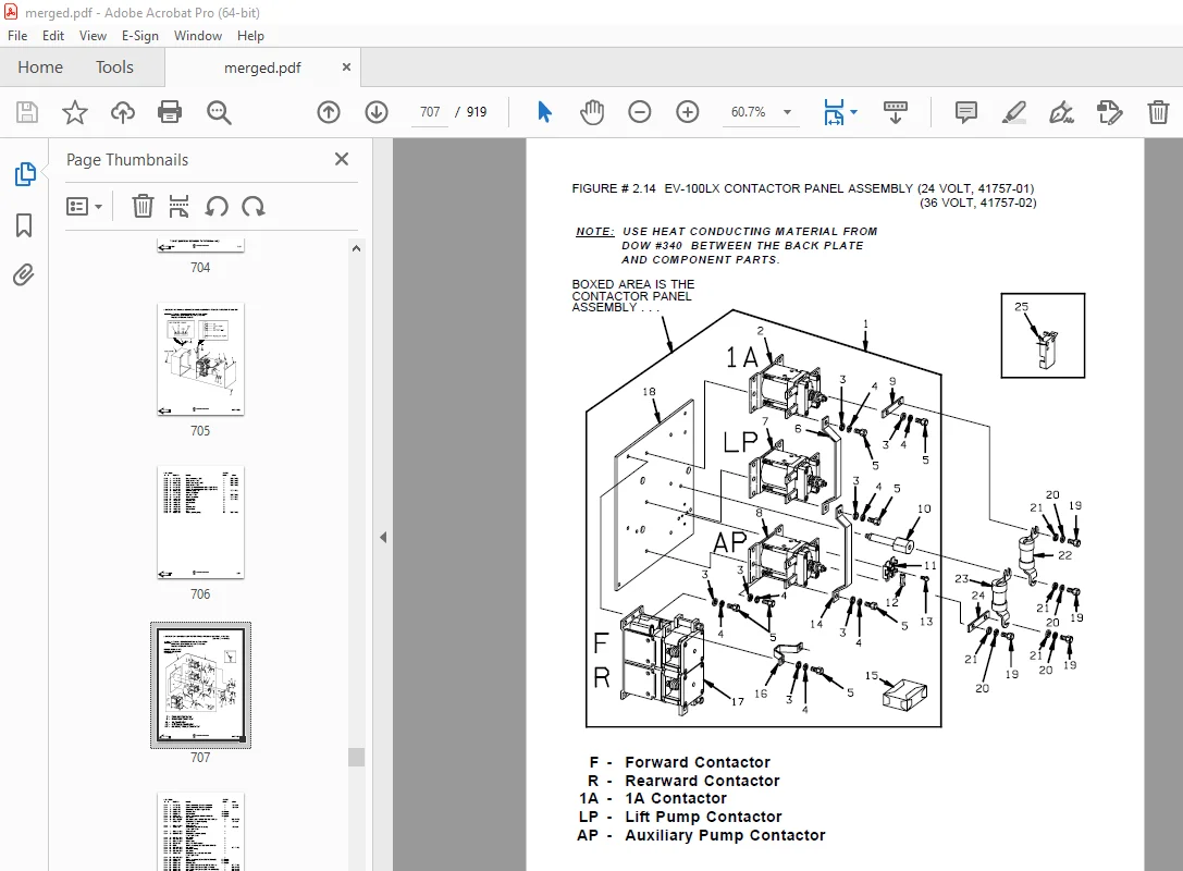
Figure # 2 14 EV-100LX Contactor Panel Assembly, 24 & 36 Volt 707
Figure # 2 15 EV-100LX SCR Forward & Rearward Contactor Assembly 709
Figure # 2 16 EV-100LX SCR 1A Contactor Assembly 711
Figure # 2 17 Lift Pump Contactor Assembly, 24 & 36 Volt 713
Figure # 2 18 EV-100LX SCR Auxiliary Pump Contactor Assembly 715
Figure # 2 19 Power Connector Assembly, 24 & 36 Volt 717
Figure # 2 20 Lift Pump Motor Assembly, 24 & 36 Volt 719
Figure # 2 20A Lift Pump Motor Assembly, 36 Volt 721
Figure # 2 21 Drive Motor Assembly, 24 & 36 Volt 723
Figure # 2 22 Auxiliary Pump Motor Assembly, 24 & 36 Volt 725
Figure # 2 23 Warning Light Assembly, 24 & 36 Volt 727
Figure # 2 24 “E” EV-100LX TT SCR Electrical Schematic 729
Figure # 2 25 “E” EV-100LX TT SCR Electrical Schematic Symbols 730
Figure # 2 26 “EE” EV-100LX TT SCR Electrical Schematic 731
Figure # 2 27 “EE” EV-100LX TT SCR Electrical Schematic Symbols 732
Figure # 2 28 EV-100LX Dash Display Installation 733
Figure # 2 29A TX EV-100LX Electrical Schematic – 3 Function Control Handle 735
Figure # 2 30A EV-100LX SCR Electrical Schematic Symbols 736
Figure # 2 29B TT EV-100LX Electrical Schematic – 3 Function Control Handle 737
Figure # 2 30B EV-100LX SCR Electrical Schematic Symbols 738
Figure # 2 31 Wiring Harness Assembly for 3 Function Control Valve 739
Figure # 3 1 Hydraulic Schematic 741
Figure # 3 2 Hydraulic Schematic Symbols 742
Figure # 3 3 Auxiliary Pump and Reservoir Assembly 743
Figure # 3 4 Auxiliary Control Valve Assembly 745
Figure # 3 5 Auxiliary Pump and Motor Assembly, 24 & 36 Volt 747
Figure # 3 6 Auxiliary Pump Assembly 749
Figure # 3 7 Hydraulic Reservoir Assembly 751
Figure # 3 8 Torque Generator Assembly 753
Figure # 3 9 Two Stage Mast Hydraulic Assembly 755
Figure # 3 10 Three Stage Mast Hydraulic Assembly 757
Figure # 3 11 Single Reach, Reach Cylinder Hose Installation 759
Figure # 3 12 Reach Diverter Valve Assembly 761
Figure # 3 13 Reach Cylinder Assembly 763
Figure # 3 14 Tilt and Sideshift Hose Installation 765
Figure # 3 15 Tilt Cylinder Assembly 767
Figure # 3 16 Lift Pump and Reservoir Assembly 769
Figure # 3 17 Lift Pump Motor Assembly 771
Figure # 3 18 Lift Pump Assembly 773
Figure # 3 19 Lift Pump Motor Assembly, 36 Volt 775
Figure # 3 20 Lift Control Valve Assembly 777
Figure # 3 21 Two Stage Cylinder and Reservoir Assembly 779
Figure # 3 22 Two Stage Cylinder Assembly 781
Figure # 3 23 Three Stage Cylinder and Reservoir Assembly 783
Figure # 3 24 Three Stage Staging Cylinder Assembly 785
Figure # 3 25 Three Stage Freelift Cylinder Assembly 787
Figure # 3 26 Hydraulic Schematic for 3 Function Control Handle 789
Figure # 3 27 Hydraulic Schematic Symbols 790
Figure # 3 28 Auxiliary Pump & Reservoir Assy for 3 Function Control Handle 791
Figure # 3 29 Valve Assembly 793
Figure # 3 30 Two Stage Mast Hydraulic Assy for 3 Function Control Handle 795
Figure # 3 31 Three Stage Mast Hydraulic Assy for 3 Function Control Handle 797
Figure # 4 1 Shielding Assembly 799
Figure # 4 2 Emergency Disconnect Assembly 801
Figure # 4 3 Auxiliary Control Assembly 803
Figure # 4 4 Hand Lift/Lower and Speed Control 805
Figure # 4 5 Forward Steering Control Assembly 807
Figure # 4 6 Rearward Steering Control Assembly 809
Figure # 4 7 Auxiliary Pump and Motor Installation 811
Figure # 4 8 Main Frame and Load Wheel Assembly 813
Figure # 4 9 Single Load Wheel Assembly 815
Figure # 4 9A Single Load Wheel Assembly 817
Figure # 4 10 5″ High Articulating Load Wheel Assembly 819
Figure # 4 10A 5″ High Articulating Load Wheel Assembly 821
Figure # 4 11 4″ High Articulating Load Wheel Assembly 823
Figure # 4 11A 4″ High Articulating Load Wheel Assembly 825
Figure # 4 12 Caster Assembly 827
Figure # 4 13 Hand Lift/Lower and Speed Control for 3 Function Control 829
Figure # 5 1 Two Stage Mast Installation 831
Figure # 5 2 Two Stage Inner Column Assembly 833
Figure # 5 3 Two Stage Outer Column Assembly 835
Figure # 5 4 Two Stage Cylinder Assembly 837
Figure # 5 5 Two Stage Reach Assembly 839
Figure # 5 6 Two Stage Reach Front Frame 841
Figure # 5 7 Two Stage Sideshifter Assembly 843
Figure # 5 8 Two Stage Fork Assembly 845
Figure # 5 9 Three Stage Mast Installation 847
Figure # 5 10 Three Stage Inner Column Assembly 849
Figure # 5 11 Three Stage Freelift Cylinder Installation 851
Figure # 5 12 Three Stage Intermediate Column Assembly 853
Figure # 5 13 Three Stage Outer Column Assembly 855
Figure # 5 14 Three Stage Reach Assembly 857
Figure # 5 15 Three Stage Reach Front Frame Assembly 859
Figure # 5 16 Three Stage Sideshifter Assy 861
Figure # 5 17 Three Stage Fork Assembly 863
Figure # 6 1 Remote Lift/Lower EV-100 LX SCR Electrical Schematic 865
Figure # 6 2 Remote Lift/Lower EV-100 LX SCR Electrical Schematic Symbols 866
Figure # 6 3 Remote Lift/Lower Wiring Harness Assembly 867
Figure # 6 4 Remote Lift/Lower Three Stage Mast Cable Assembly 869
Figure # 6 5 Remote Lift/Lower Reach and Platform Cable Assembly 871
Figure # 6 6 Remote Lift/Lower Power Component Wiring 873
Figure # 6 7 Remote Lift/Lower Connector Assembly 875
Figure # 6 8 Remote Lift/Lower Hydraulic Schematic 877
Figure # 6 9 Remote Lift/Lower Manlift Hydraulic Schematic Symbols 878
Figure # 6 10 Remote Lift/Lower Hydraulic Diagram 879
Figure # 6 11 Blocking Remote Lift/Lower Valve Assembly 881
Figure # 6 12 Remote Lift/Lower Valve Assembly 883
Figure # 6 13 Remote Lift/Lower Load Backrest Installation 885
Figure # 6 14 Remote Lift/Lower Contactor Assembly 887
Figure # 7 1 Battery Lift Interrupt “E” EV-100LX SCR Electrical Schematic 889
Figure # 7 2 Battery Lift Interrupt “E” EV-100LX SCR Electrical Schematic Symbols 890
Figure # 7 3 Battery Lift Interrupt “EE” EV-100LX SCR Electrical Schematic 891
Figure # 7 4 Battery Lift Interrupt “EE” EV-100LX SCR Electric Schematic Symbols 892
Figure # 7 5 Battery Lift Interrupt Installation 893
Figure # 10 1 Special Tools and Lubrications 895
Numerical Index 898
DESCRIPTION:
BT Prime Mover RR-34B Reach Truck Parts Manual – PDF DOWNLOAD
PARTS ORDERING INSTRUCTIONS :
HOW TO ORDER:
- When you order, supply the part number, quantity, model and serial numbers of your machine. Supplying this information will assure prompt, efficient handling of your order. The pictorial reference number is not needed and including it can only add confusion.
- Since your dealer carries many parts in stock and maintains up-to-date prices on all parts, he will be able to process your order immediately. If, for some reason, the part is not in stock, he will order it from the factory. In either event, he maintains a current file of service manuals, which give all available parts ordering or technical information.
- All prices are FOB factory in Muscatine, Iowa. Shipping charges are added to the price of the part shipping from the factory.
WHERE TO ORDER:
Always order parts from the dealer who sold you your Prime-Mover. If it is necessary for the dealer to order parts from the factory, he is able to get prompt service for you. Parts are shipped in accordance with shipping instructions given on the order.
S.V 12/01/2025