BT Prime-Mover RR-45Z Reach Truck Parts Catalog PDF
$31.95
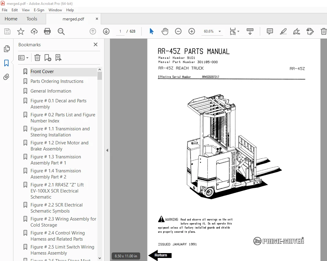
BT Prime-Mover RR-45Z Reach Truck Parts Manual – PDF DOWNLOAD
Description
BT Prime-Mover RR-45Z Reach Truck Parts Manual – PDF DOWNLOAD
FILE DETAILS:
BT Prime-Mover RR-45Z Reach Truck Parts Manual – PDF DOWNLOAD
Language : English
Pages : 628
Downloadable : Yes
File Type : PDF
IMAGES PREVIEW OF THE MANUAL:
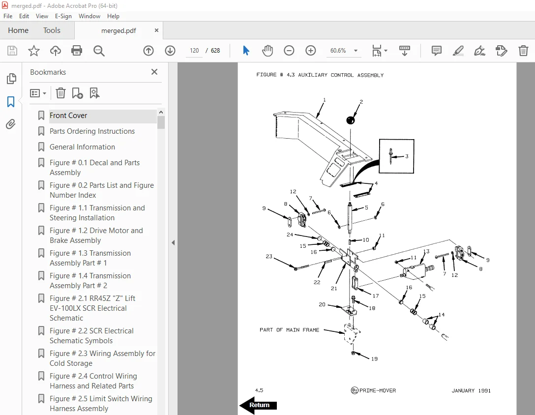
TABLE OF CONTENTS:
BT Prime-Mover RR-45Z Reach Truck Parts Manual – PDF DOWNLOAD
Front Cover 1
Parts Ordering Instructions 2
General Information 3
Figure # 0 1 Decal and Parts Assembly 4
Figure # 0 2 Parts List and Figure Number Index 6
Figure # 1 1 Transmission and Steering Installation 8
Figure # 1 2 Drive Motor and Brake Assembly 10
Figure # 1 3 Transmission Assembly Part # 1 12
Figure # 1 4 Transmission Assembly Part # 2 14
Figure # 2 1 RR45Z “Z” Lift EV-100LX SCR Electrical Schematic 16
Figure # 2 2 SCR Electrical Schematic Symbols 17
Figure # 2 3 Wiring Assembly for Cold Storage 18
Figure # 2 4 Control Wiring Harness and Related Parts 20
Figure # 2 5 Limit Switch Wiring Harness Assembly 22
Figure # 2 6 Three Stage Mast Cable Assembly 24
Figure # 2 7 Single Reach Cable Assembly 26
Figure # 2 8 Double Reach Cable Assembly 28
Figure # 2 9 EV-100LX Power Component Wiring 30
Figure # 2 10 EV-100LX TX & TT SCR Control Panel 32
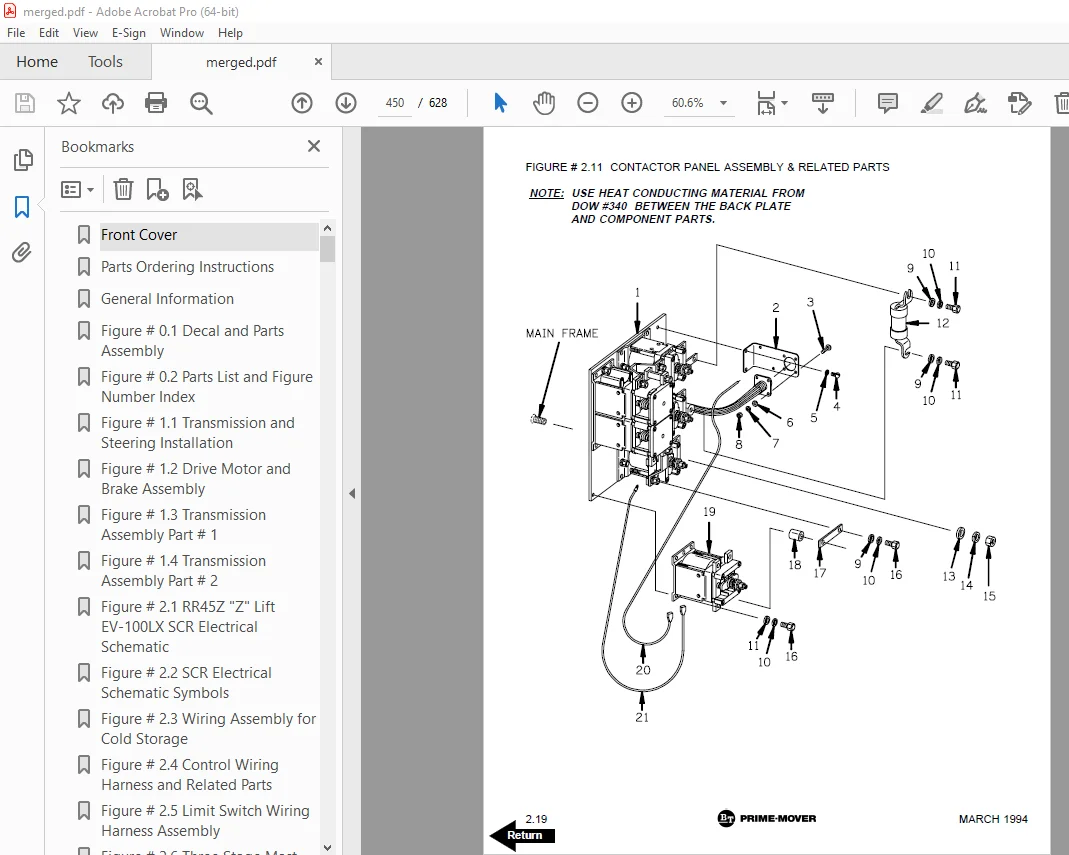
Figure # 2 11 Contactor Panel Assembly & Related Parts 34
Figure # 2 12 EV-100LX Contactor Panel Assembly 36
Figure # 2 13 Forward & Rearward Contactor Assembly 38
Figure # 2 14 1A Contactor Assembly 40
Figure # 2 15 Lift Pump Contactor Assembly 42
Figure # 2 16 Auxiliary Pump Contactor Assembly 44
Figure # 2 17 Power Connector Assembly 46
Figure # 2 18 Lift Pump Motor Assembly 48
Figure # 2 19 Drive Motor Assembly 50
Figure # 2 20 Auxiliary Pump Motor Assembly 52
Figure # 2 21 Warning Light Assembly 54
Figure # 2 22 EV-100LX TT Electrical Schematic 56
Figure # 2 23 EV-100LX TT Electrical Schematic Symbols 57
Figure # 2 24 EV-100LX Dash Display Installation 58
Figure # 3 1 RR45Z “Z” Lift EV-100LX Hydraulic Schematic 60
Figure # 3 2 Hydraulic Schematic Symbols 61
Figure # 3 3 Auxiliary Pump and Reservoir Assembly 62
Figure # 3 4 Auxiliary Control Valve Assembly 64
Figure # 3 5 Auxiliary Pump Assembly 66
Figure # 3 6 Hydraulic Reservoir Assembly 68
Figure # 3 7 Steering Control Valve Assembly 70
Figure # 3 8 Steering Control Valve and Hose Assembly 72
Figure # 3 9 Steering Cylinder Assembly 74
Figure # 3 10 “Z” Lift EV-100LX Three Stage Mast Hydraulic Assembly 76
Figure # 3 11 Single Reach, Reach Cylinder Hose Installation 78
Figure # 3 12 Single Reach Diverter Valve Assembly 80
Figure # 3 13 Single Reach, Reach Cylinder Assembly 82
Figure # 3 14 Single Reach, Tilt and Sideshifter 84
Figure # 3 15 Single Reach, Tilt Cylinder Assembly 86
Figure # 3 16 Double Reach with Tilt and Sideshifter 88
Figure # 3 17 Double Reach Diverter Valve Assembly 90
Figure # 3 18 Double Reach, Reach Cylinder Assembly 92
Figure # 3 19 Double Reach, Tilt Cylinder Assembly 94
Figure # 3 20 Lift Pump and Reservoir Assembly 96
Figure # 3 21 Lift Pump and Motor Assembly 98
Figure # 3 22 Lift Pump Assembly 100
Figure # 3 23 Lift Control Valve Assembly 102
Figure # 3 24 Three Stage Cylinder and Reservoir Assembly 104
Figure # 3 25 Three Stage Staging Cylinder Assembly 106
Figure # 3 26 Three Stage Freelift Cylinder Assembly 108
Figure # 3 27 Brake Master Cylinder 110
Figure # 3 28 Drive Motor Brake Cylinder 112
Figure # 3 29 Idler Wheel Brake Cylinder 114
Figure # 4 1 Shielding Assembly 116
Figure # 4 2 Emergency Disconnect Assembly 118
Figure # 4 3 Auxiliary Control Assembly 120
Figure # 4 4 Hand Lift/Lower and Speed Control 122
Figure # 4 5 Brake Linkage and Cylinder Assembly 124
Figure # 4 6 Steering Control Assembly 126
Figure # 4 7 Idler Wheel Installation 128
Figure # 4 8 Idler Wheel Assembly 130
Figure # 4 9 Main Frame and Load Wheel 132
Figure # 4 10 Single Load Wheel Assembly 134
Figure # 4 11 5″ High Articulating Load Wheel Assembly 136
Figure # 4 12 4″ High Articulating Load Wheel 138
Figure # 5 1 Three Stage Mast Installation 140
Figure # 5 2 Three Stage Inner Column Assembly 142
Figure # 5 3 Three Stage Freelift Cylinder Installation 144
Figure # 5 4 Three Stage Intermediate Column Assembly 146
Figure # 5 5 Three Stage Outer Column Assembly 148
Figure # 5 6 Single Reach Assembly 150
Figure # 5 7 Single Reach with Front Frame 152
Figure # 5 8 Double Reach Assembly 154
Figure # 5 9 Double Reach with Front Frame 156
Figure # 5 10 Sideshifter Assembly 158
Figure # 5 11 Fork Assembly 160
Figure # 7 1 Special Tools and Lubrications 162
Numerical Index 165
Back Cover 186
Front Cover 187
Parts Ordering Instructions 188
Field Modifications 188
General Information 189
Alphabetical Index 190
Figure # 0 1 Decals and Parts Assembly 194
Figure # 1 1 Transmission and Steering Installation 196
Figure # 1 2 Drive Motor Brake Assembly 198
Figure # 1 3 Transmission Assembly Part # 1 200
Figure # 1 4 Transmission Assembly Part # 2 202
Figure # 2 1 RR45Z “Z” Lift EV-100LX SCR Electrical Schematic 204
Figure # 2 2 RR45Z “Z” Lift EV-100LX SCR Electrical Schematic Symbols 205
Figure # 2 3 Wiring Assembly for Cold Storage 206
Figure # 2 4 RR45Z “Z” Lift Control Wiring Harness 208
Figure # 2 5 Limit Switch Wiring Assembly 210
Figure # 2 6 Three Stage Mast Cable Assembly 212
Figure # 2 7 Single Reach Cable Assembly 214
Figure # 2 8 Double Reach Cable Assembly 216
Figure # 2 9 EV-100LX Power Component Wiring 218
Figure # 2 10 EV-100LX TX & TT SCR Control Panel Assembly 220
Figure # 2 11 Contactor Panel Assembly & Related Parts 222
Figure # 2 12 EV-100LX Contactor Panel Assembly 224
Figure # 2 13 EV-100LX SCR Forward & Rearward Contactor Assembly 226
Figure # 2 14 EV-100LX SCR 1A Contactor Assembly 228
Figure # 2 15 Lift Pump Contactor Assembly 230
Figure # 2 16 EV-100LX SCR Auxiliary Pump Contactor Assembly 232
Figure # 2 17 Power Connector Assembly, 36 Volt 234
Figure # 2 18 Lift Pump Motor Assembly 236
Figure # 2 19 Drive Motor Assembly 238
Figure # 2 20 Auxiliary Pump Motor Assembly 240
Figure # 2 21 Warning Light Assembly 242
Figure # 2 22 EV-100LX TT Electrical Schematic 244
Figure # 2 23 EV-100LX TT Electrical Schematic Symbols 245
Figure # 2 24 EV-100LX Dash Display Installation 246
Figure # 2 25 EV-100LX SCR Electrical Schematic – 3 Function Control Handle 248
Figure # 2 26 EV-100LX SCR Electrical Schematic Symbols 249
Figure # 2 27 Wiring Harness Assembly for 3 Function Control Valve 250
Figure # 2 30 RR45 “Z” EV-100LX TT SCR Electrical Schematic – Three Function Control Handle 252
Figure # 2 31 EV-100LX SCR Electrical Schematic Symbols 253
Figure # 3 1 Hydraulic Schematic for 3 Function Control Handle 254
Figure # 3 2 Hydraulic Schematic Symbols 255
Figure # 3 3 Auxiliary Pump and Reservoir Assembly 256
Figure # 3 4 Auxiliary Control Valve Assembly (not used with multi-function handle) 258
Figure # 3 5 Auxiliary Pump and Motor Assembly 260
Figure # 3 6 Auxiliary Pump Assembly 262
Figure # 3 7 Hydraulic Reservoir Assembly 264
Figure # 3 8 Steering Control Valve Assembly 266
Figure # 3 9 Steering Control Valve and Hose Assembly 268
Figure # 3 10 Steering Cylinder Assembly 270
Figure # 3 11 Three Stage Mast Hydraulic Assembly 272
Figure # 3 12 Single Reach, Reach Cylinder Hose Installation 274
Figure # 3 13 Single Reach Diverter Valve Assembly 276
Figure # 3 14 Single Reach, Cushion Reach Cylinder Assembly 278
Figure # 3 15 Single Reach, Tilt and Sideshift Hose Installation 280
Figure # 3 16 Double Reach with Tilt and Sideshifter 282
Figure # 3 17 Double Reach, Reach Cylinder Assembly 284
Figure # 3 18 Double Reach Diverter Valve Assembly 286
Figure # 3 19 Double Reach, Tilt Cylinder Assembly 288
Figure # 3 20 Double Reach, Reach Cylinder Assembly 290
Figure # 3 21 Double Reach, Tilt Cylinder Assembly 292
Figure # 3 22 Lift Pump Motor and Reservoir Assembly 294
Figure # 3 23 Lift Pump Motor Assembly 296
Figure # 3 24 Lift Pump Motor Assembly, 24 Volt 298
Figure # 3 25 Lift Pump Motor Assembly, 36 Volt 300
Figure # 3 26 Lift Control Valve Assembly 302
Figure # 3 27 Three Stage Cylinder and Reservoir Assembly 304
Figure # 3 28 Three Stage Staging Cylinder Assembly 306
Figure # 3 29 Three Stage Freelift Cylinder Assembly 308
Figure # 3 30 Brake Linkage and Cylinder Assembly 310
Figure # 3 31 Brake Master Cylinder 312
Figure # 3 32 Drive Motor Brake Cylinder 314
Figure # 3 33 Idler Wheel Brake Cylinder 316
Figure # 3 36 Auxiliary Pump & Reservoir Assembly for 3 Function Control Handle 318
Figure # 3 37 Valve Assembly 320
Figure # 3 38 Three Stage Mast Hydraulic Assembly for 3 Function Control Handle 322
Figure # 4 1 Shielding Assembly 324
Figure # 4 2 Emergency Disconnect Assembly 326
Figure # 4 3 Auxiliary Control Assembly 328
Figure # 4 4 Hand Lift/Lower and Speed Control 330
Figure # 4 5 Steering Control Assembly 332
Figure # 4 6 Idler Wheel Installation 334
Figure # 4 7 Idler Wheel Assembly 336
Figure # 4 8 Main Frame and Load Wheel Assembly 338
Figure # 4 9 Single Load Wheel Assembly 340
Figure # 4 10 5″ High Articulating Load Wheel Assembly 342
Figure # 4 11 4″ High Articulating Load Wheel Assembly 344
Figure # 4 13 Hand Lift/Lower and Speed Control for 3 Function Control 346
Figure # 5 1 Three Stage Mast Installation 348
Figure # 5 2 Three Stage Inner Column Assembly 350
Figure # 5 3 Three Stage Freelift Cylinder Installation 352
Figure # 5 4 Three Stage Intermediate Column Assembly 354
Figure # 5 5 Three Stage Outer Column Assembly 356
Figure # 5 6 Single Reach Assembly 358
Figure # 5 7 Single Reach with Front Frame 360
Figure # 5 8 Double Reach Assembly 362
Figure # 5 9 Double Reach with Front Frame 364
Figure # 5 10 Sideshifter Assembly 366
Figure # 5 11 Fork Assembly 368
Figure # 6 1 Manlift EV-100 LX SCR Electrical Schematic 370
Figure # 6 2 Manlift EV-100 LX SCR Electrical Schematic Symbols 371
Figure # 6 3 Manlift Wiring Harness Assembly 372
Figure # 6 4 Manlift Three Stage Mast Cable Assembly 374
Figure # 6 5 Manlift Reach and Platform Cable Assembly 376
Figure # 6 6 Manlift Power Component Wiring 378
Figure # 6 7 Manlift Connector Assembly 380
Figure # 6 8 Manlift Hydraulic Schematic 382
Figure # 6 9 Manlift Hydraulic Schematic Symbols 383
Figure # 6 10 Manlift Hydraulic Diagram 384
Figure # 6 11 Blocking Manlift Valve Assembly 386
Figure # 6 12 Manlift Valve Assembly 388
Figure # 6 13 Manlift Load Backrest Installation 390
Figure # 10 1 Special Tools and Lubrications 392
Numerical Index 395
Back Cover 414
Front Cover 415
Parts Ordering Instructions 416
General Information 417
Alphabetical Index 418
Figure # 0 1 Decals and Parts Assembly 422
Figure # 1 1 Transmission and Steering Installation 424
Figure # 1 2 Drive Motor Brake Assembly 426
Figure # 1 3 Transmission Assembly, Part # I 428
Figure # 1 4 Transmission Assembly, Part # II 430
Figure # 2 1 EV-100LX SCR Electrical Schematic 432
Figure # 2 2 EV-100LX SCR Electrical Schematic Symbols 433
Figure # 2 3 Wiring Assembly for Cold Storage 434
Figure # 2 4 Lift Control Wiring Harness 436
Figure # 2 5 Limit Switch Wiring Assembly 438
Figure # 2 6 Three Stage Mast Cable Assembly 440
Figure # 2 7 Single Reach Cable Assembly 442
Figure # 2 8 Double Reach Cable Assembly 444
Figure # 2 9 EV-100LX Power Component Wiring 446
Figure # 2 10 EV-100LX TX & TT SCR Control Panel Assembly 448
Figure # 2 11 Contactor Panel Assembly & Related Parts 450
Figure # 2 12 EV-100LX Contactor Panel Assembly 452
Figure # 2 13 EV-100LX SCR Forward & Rearward Contactor Assembly 454
Figure # 2 14 EV-100LX SCR 1A Contactor Assembly 456
Figure # 2 15 Lift Pump Contactor Assembly 458
Figure # 2 16 EV-100LX SCR Auxiliary Pump Contactor Assembly 460
Figure # 2 17 Power Connector Assembly, 36 Volt 462
Figure # 2 18 Lift Pump Motor Assembly 464
Figure # 2 19 Drive Motor Assembly 466
Figure # 2 20 Auxiliary Pump Motor Assembly 468
Figure # 2 21 Warning Light Assembly 470
Figure # 2 22 EV-100LX TT SCR Electrical Schematic 472
Figure # 2 23 EV-100LX TT SCR Electrical Schematic Symbols 473
Figure # 2 24 EV-100LX Dash Display Installation 474
Figure # 2 25 TT SCR Electrical Schematic Three Function Control Handle 476
Figure # 2 26 EV-100LX SCR Electrical Schematic Symbols 477
Figure # 2 27 Wiring Harness Assembly for 3 Function Control Valve 478
Figure # 3 1 Hydraulic Schematic for 3 Function Control Handle 480
Figure # 3 2 Hydraulic Schematic Symbols 481
Figure # 3 3 Auxiliary Pump and Reservoir Assembly 482
Figure # 3 4 Auxiliary Control Valve Assembly 484
Figure # 3 5 Auxiliary Pump and Motor Assembly, 36 Volt 486
Figure # 3 6 Auxiliary Pump Assembly 488
Figure # 3 7 Hydraulic Reservoir Assembly 490
Figure # 3 8 Steering Control Valve Assembly 492
Figure # 3 9 Steering Control Valve and Hose Assembly 494
Figure # 3 10 Steering Cylinder Assembly 496
Figure # 3 11 Three Stage Mast Hydraulic Assembly 498
Figure # 3 12 Single Reach, Reach Cylinder Hose Installation 500
Figure # 3 13 Single Reach Diverter Valve Assembly 502
Figure # 3 14 Single Reach, Reach Cylinder Assembly 504
Figure # 3 15 Single Reach, Tilt and Sideshift Hose Installation 506
Figure # 3 16 Single Reach, Tilt Cylinder Assembly 508
Figure # 3 17 Double Reach with Tilt and Sideshifter 510
Figure # 3 18 Double Reach Diverter Valve Assembly 512
Figure # 3 19 Double Reach, Reach Cylinder Assembly 514
Figure # 3 20 Double Reach, Tilt Cylinder Assembly 516
Figure # 3 21 Lift Pump Motor and Reservoir Assembly 518
Figure # 3 22 Lift Pump Motor Assembly 520
Figure # 3 23 Lift Pump Assembly 522
Figure # 3 24 Lift Control Valve Assembly 524
Figure # 3 25 Three Stage Cylinder and Reservoir Assembly 526
Figure # 3 26 Three Stage Staging Cylinder Assembly 528
Figure # 3 27 Three Stage Freelift Cylinder Assembly 530
Figure # 3 28 Brake Linkage and Cylinder Assembly 532
Figure # 3 29 Brake Master Cylinder 534
Figure # 3 30 Drive Motor Brake Cylinder 536
Figure # 3 31 Idler Wheel Brake Cylinder 538
Figure # 3 32 Auxiliary Pump & Reservoir Assy for 3 Function Control Handle 540
Figure # 3 33 Valve Assembly 542
Figure # 3 34 Three Stage Mast Hydraulic Assembly for 3 Function Control Handle 544
Figure # 4 1 Shielding Assembly 546
Figure # 4 2 Emergency Disconnect Assembly 548
Figure # 4 3 Auxiliary Control Assembly 550
Figure # 4 4 Hand Lift/Lower and Speed Control 552
Figure # 4 5 Steering Control Assembly 554
Figure # 4 6 Idler Wheel Installation 556
Figure # 4 7 Idler Wheel Assembly 558
Figure # 4 8 Main Frame and Load Wheel Assembly 560
Figure # 4 9 Single Load Wheel Assembly 562
Figure # 4 9A Single Load Wheel Assembly 564
Figure # 4 10 5″ High Articulating Load Wheel Assembly 566
Figure # 4 10A 5″ High Articulating Load Wheel Assembly 568
Figure # 4 11 4″ High Articulating Load Wheel Assembly 570
Figure # 4 11A 4″ High Articulating Load Wheel Assembly 572
Figure # 4 12 Hand Lift/Lower and Speed Control for 3 Function Control 574
Figure # 5 1 Three Stage Mast Installation 576
Figure # 5 2 Three Stage Inner Column Assembly 578
Figure # 5 3 Three Stage Freelift Cylinder Installation 580
Figure # 5 4 Three Stage Intermediate Column Assembly 582
Figure # 5 5 Three Stage Outer Column Assembly 584
Figure # 5 6 Three Stage Single Reach Assembly 586
Figure # 5 7 Three Stage Single Reach Front Frame Assembly 588
Figure # 5 8 Three Stage Double Reach Assembly 590
Figure # 5 9 Three Stage Double Reach Front Frame Assembly 592
Figure # 5 10 Three Stage Sideshifter Assembly 594
Figure # 5 11 Three Stage Fork Assembly 596
Figure # 7 1 TX SCR Electric Schematic – Three Function Control Handle 598
Figure # 7 2 Battery Lift Interrupt Electrical Schematic Symbols 599
Figure # 7 3 Battery Lift Interrupt EV-100LX SCR Electrical Schematic 600
Figure # 7 4 Battery Lift Interrupt Electrical Schematic Symbols 601
Figure # 7 5 Battery Lift Interrupt Installation 602
Figure # 10 1 Special Tools and Lubrications 604
Numerical Index 607
Back Cover 628
DESCRIPTION:
BT Prime-Mover RR-45Z Reach Truck Parts Manual – PDF DOWNLOAD
Manual Number 9101
Manual Part Number 301185-000
RR-45Z REACH TRUCK
Effect Serial Number RR45Z0207217
PARTS ORDERING INSTRUCTIONS:
HOW TO ORDER:
- When you order, supply the part number, quantity, model and serial numbers of your machine. Supplying this information will assure prompt, efficient handling of your order. The pictorial reference number is not needed and including it can only add confusion.
- Since your dealer carries many parts in stock and maintains up-to-date prices on all parts, he will be able to process your order immediately. If, for some reason, the part is not in stock, he will order it from the factory. In either event, he maintains a current file of service manuals, which give all available parts ordering or technical information.
- All prices are FOB factory in Muscatine, Iowa. Shipping charges are added to the price of the part shipping from the factory.
WHERE TO ORDER:
Always order parts from the dealer who sold you your PRIME-MOVER . If it is necessary for the dealer to order parts from the factory, he is able to get prompt service for you. Parts are shipped in accordance with shipping instructions given on the order.
S.V 01/02/2025