BT Prime-Mover RS-20 RS-30 RS-40 RR-20 RDR-25 RR-30 Truck Operating & Parts Manual PDF
$30.95
BT Prime-Mover RS-20 RS-30 RS-40 RR-20 RDR-25 RR-30 Truck Operating Maintenance & Parts Manual – PDF DOWNLOAD
RS Series Trucks
310680-000 RS-40 OMP Manual 1970_September
310083-000 RS20/30/40 OMP Manual After March 01, 1974
302217-000 RS20/30/40 OMP Manual After March 01, 1974 with Serial Number 1504
RR Series Trucks
310509-000 1973_December
302215-000 RR-20/30 OMP Manual After March 01, 1974
302216-000 RR-30/20 OMP Manual After March 01, 1974 with Serial Number 1504
RS/RR Series Trucks
301074-000 1983_June
Description
BT Prime-Mover RS-20 RS-30 RS-40 RR-20 RDR-25 RR-30 Truck Operating Maintenance & Parts Manual – PDF DOWNLOAD
FILE DETAILS:
BT Prime-Mover RS-20 RS-30 RS-40 RR-20 RDR-25 RR-30 Truck Operating Maintenance & Parts Manual – PDF DOWNLOAD
Language : English
Pages : 552
Downloadable : Yes
File Type : PDF
IMAGES PREVIEW OF THE MANUAL:
TABLE OF CONTENTS:
BT Prime-Mover RS-20 RS-30 RS-40 RR-20 RDR-25 RR-30 Truck Operating Maintenance & Parts Manual – PDF DOWNLOAD
RS Series Trucks
310680-000 RS-40 OMP Manual 1970_September
310083-000 RS20/30/40 OMP Manual After March 01, 1974
302217-000 RS20/30/40 OMP Manual After March 01, 1974 with Serial Number 1504
RR Series Trucks
310509-000 1973_December
302215-000 RR-20/30 OMP Manual After March 01, 1974
302216-000 RR-30/20 OMP Manual After March 01, 1974 with Serial Number 1504
RS/RR Series Trucks
301074-000 1983_June
Front Cover 2
Warranty 3
New Owners 4
Contents 4
Preliminary Service 4
Operation Insutructions 4
Operating Rules and Instructions 5
Lubrication Chart 10
Maintenance Instructions 11
Service and Disassembly Instructions 14
Parts Ordering Instructions 26
RS20 Specifications 27
RS30 Specifications 28
RS40 Specifications 29
RR20 Specifications 30
RR30 Specifications 31
Figure # 1 Decal and Parts Assembly 33
Figure # 2 Parts List and Service Reference Index 35
Figure # 3 Shielding Assembly 38
Figure # 4 Drive Mounting 40
Figure # 5 14:1 Transmission Assembly with MKU-4006 Drive Motor 42
Figure # 6 Motor Assembly 44
Figure # 7 Brake Linkage 45
Figure # 8 Slave Cylinder Assembly 47
Figure # 9 Master Cylinder Assembly 48
Figure # 10 Steering Linkage 49
Figure # 11 Steering Assembly 50
Figure # 12 Power Steering Gear Box 52
Figure # 13 Torque Generator 53
Figure # 14 Forward Gear Reduction Steering Gear Box, Reverse Chain Reduction Steering Gear Box 54
Figure # 15 GE Electrical Schematic – Model EV-1 55
Figure # 16 Electrical Schematic Symbols 56
Figure # 17 Wiring Harness Assembly 57
Figure # 18 Power Component Assembly 59
Figure # 19 SCR and Contactor Panel Assembly 60
Figure # 20 EV-1 SCR Control 61
Figure # 21 Transformer Assembly 62
Figure # 22 Rectifier Heat Sink Assembly 63
Figure # 23 GE Contactor Assembly 64
Figure # 24 Power Steering Contactor Assembly 65
Figure # 25 GE Contactor Assembly 66
Figure # 26 Warning Light Assembly 67
Figure # 27 Connector Assembly 68
Figure # 28 Handle Assembly 69
Figure # 29 Master Control Switch Assembly 70
Figure # 30 Master Control Switch Assembly 71
Figure # 31 Hydraulic Schematic 72
Figure # 32 Hydraulic Schematic Symbols 73
Figure # 33 Hydraulic Assembly (2 Stage) 74
Figure # 34 Hydraulic Assembly – Part # 1 75
Figure # 35 Tilt Cylinder Assembly and Related Parts 77
Figure # 36 Tilt Cylinder Assembly 78
Figure # 37 Lift Cylinder and Related Parts 79
Figure # 38 2″ Lift Cylinder Assembly 80
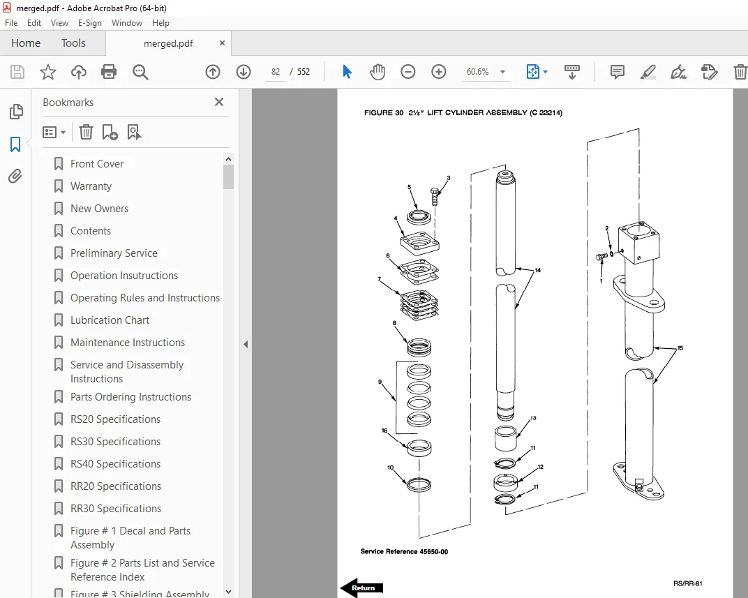
Figure # 39 2 1/2″ Lift Cylinder Assembly 82
Figure # 40 2 3/4″ Lift Cylinder Assembly 84
Figure # 41 Hydraulic Assembly (3 Stage) 86
Figure # 42 Hydraulic Assembly (3 Stage) Part # 2 87
Figure # 43 3 Stage Staging Cylinder Assembly 89
Figure # 44 Freelift Cylinder Assembly 90
Figure # 45 Hydraulic Assembly Part # 3 91
Figure # 46 Pump and Motor Assembly 92
Figure # 47 Motor Assembly 93
Figure # 48 Power Steering Pump Assembly 94
Figure # 50 Control Valve Assembly 97
Figure # 51 Control Valve Assembly 99
Figure # 52 Hydraulic Pump and Motor 100
Figure # 53 Pump Assembly 101
Figure # 54 Motor Assembly 102
Figure # 55 Motor Assembly 104
Figure # 56 Adjusting Linkage 105
Figure # 57 2 Stage Mast Assembly 106
Figure # 58 2 Stage Outer Column Assembly 108
Figure # 59 2 Stage Inner Column Assembly 109
Figure # 60 2 Stage Lift Cylinder and Related Parts 111
Figure # 61 RS-30/40 Lift Frame and Load Backrest 112
Figure # 62 RS-20 (Only) Lift Frame and Load Backrest 113
Figure # 63 3 Stage Mast Assembly 114
Figure # 64 Lift Frame Assembly 115
Figure # 65 Inner Column Assembly (3 Stage) 116
Figure # 66 Freelift Cylinder Assembly (3 Stage) 117
Figure # 67 Intermediate Column Assembly (3 Stage) 119
Figure # 68 Outer Column Assembly (3 Stage) 120
Figure # 69 Fork Assembly 121
Figure # 70 Auxiliary Hydraulic Valve Parts Breakdown 122
Figure # 71 Brudi Sideshifter 123
Figure # 72 Hydraulic Cylinder for Brudi Sideshifter 124
Figure # 73 Gleason Hose Reel Assembly (3 Stage Masts) 125
Figure # 74 Gleason Hose Reel 35 Series 126
Figure # 75 Dual Elbow Swivel Assembly 127
Figure # 76 Reach Attachment 128
Figure # 77 Reach Attachment 130
Figure # 78 Reach Attachment Hydraulic Assembly 132
Figure # 79 Reach Attachment Cylinder Assembly 133
Figure # 80 Load Wheel Assembly 135
Troubleshooting Hydraulic Gear Pump 136
Service Guide 137
Back Cover 140
Front Cover 141
Warranty 142
New Owner 143
Contents 143
Operating Instructions 144
Maintenance Chart 146
Lubrication Chart 147
Manintenance Instructions 148
Service and Disassembly Instructions 152
Parts Ordering Instructions 155
Parts List Index 156
MainFrame, Shielding, Misc 158
Drive Mounting 160
24 Volt Transmission 162
Drive Motor Service Parts for D-25901 164
Notes 165
Brake Linkage 166
Steering Linkage 167
Steering Assembly 168
Steering Reduction 169
Hydraulic Piping for RR-20/30 170
Hydraulic Valve 172
Hydraulic: Valve Mounting, Reservoir Mounting, Motor Mounting 173
Hydraulic Pump 174
Motor for P-25428 Pump/Motor Assembly 175
Tilt Cylinder Assembly 176
Adjusting Linkage 177
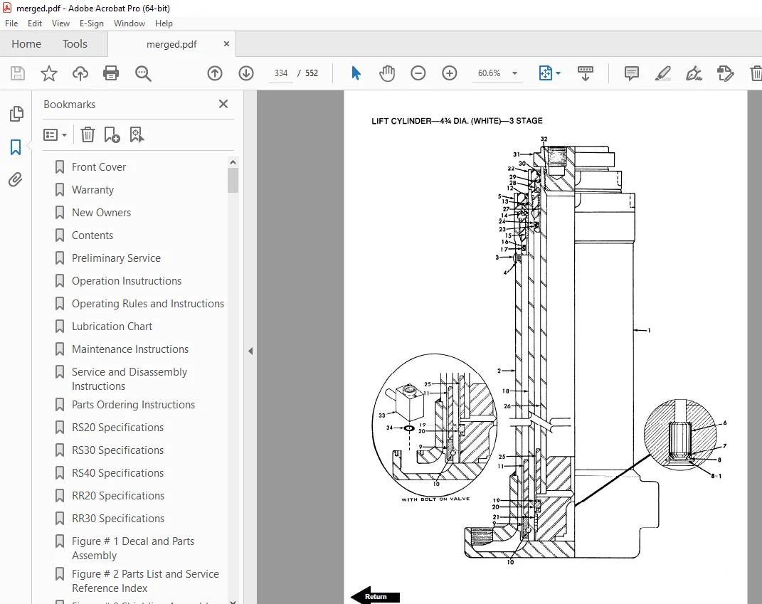
Lift Cylinder White 3 Stage Mast 178
Lift Cylinder Assembly 179
Mast — 2 Stage 180
White Masts 182
G E Electrical Schematic 184
Square D Electrical Schematic 185
Power Wiring G E System 186
Square D Power Wiring 187
Control Wiring for G E System 188
Control Wiring for Square D 189
G E Electrical Control Panel 190
SCR Control Panel — Square D System 191
Contactor Panel Square D System 192
Control Handle 193
Hour meter 194
Auxiliary Hydraulic Valve Parts Breakdown (4 function) 195
Reach Attachment 196
Brudi Hose Real Assembly for Prime-Mover Masts 199
Brudi Hose Reel 200
Cascade Hose Reel Assembly for 3 Stage Mast 201
Outboard Spring Style Hose Reels 202
Inboard Spring Style Hose Reels 202
Service Guide 203
Back Cover 205
Front Cover 206
Warranty 207
New Owners 208
Contents 208
Specification 208
Operating Rules and Instructions 209
Maintenance Chart 215
Lubrication Chart 216
Maintenance Instructions 217
Service and Disassembly Instructions 221
Parts Ordering Instructions 224
Parts List and Service Reference Index 225
Main Frame, Shielding, Misc 227
Drive Mounting 229
24 Volt Transmission Service Parts 231
Drive Motor Service Parts for D-25901 233
Drive Motor Service Parts for D-25968 234
Brake Linkage 235
Steering Linkage 236
Steering Assembly 237
Steering Reduction 238
Hydraulic Piping for RR-20/30 241
Hydraulic Control Valve 243
Hydraulic: Valve Mounting, Reservoir Mounting, Motor Mounting 244
Hydraulic Pump for P-25428 Pump/Motor Assembly 245
Motor for P-25428 Pump/Motor Assembly 246
Tilt Cylinder 247
Adjusting Linkage 248
Lift Cylinder 249
LiftCylinder Assembly — Prime-Mover 251
Prime-Mover Mast — 2 Stage 253
Reach Attachment Model RA 255
Reach Attachment Model RD 257
Knickerbocker TRI-FREE Roller — 3 Mast 259
White Masts — Three Stage 261
G E SCR Electrical Schematic — Model EV-1 263
Electrical Schematic Symbols 264
Control Wiring Ffor G E Model EV-1 System 265
Power Wiring G E Model EV-1 267
G E Model EV-1 Control 269
Contactor Panel G E Model EV-1 270
EV-1 Forward/Reverse Contactor 271
EV-1 1A, P & FW Contactor 273
Control Handle 275
Cold Storage Diagram/Components 276
Auxiliary Hydraulic Valve Parts Breakdown 278
rudi Side Shifter 279
Hydraulic Cylinder for Brudi Side Shifter 280
Brudi Hose Reel Assembly for Prime-Mover Masts 281
Brudi Hose Reel 282
Gleason Hose Reel Assembly for Three Stage Masts 283
Gleason Hose Reel 284
Service Guide 285
Back Cover 289
Front Cover 290
Warranty 291
New Oweners 292
Operating Rules and Instructions 293
Maintenance Chart 299
Lubrication Chart 300
Maintenance Instructions 301
Service and Disassembly Instructions 305
Parts Ordering Instructions 308
Parts List and Service Reference Index 309
Main Frame, Shielding, Misc 311
Drive Mounting 313
24 Volt Transmission Service Parts 315
Drive Motor Service Parts for D-25901 317
Drive Motor Service Parts for D-25968 318
Brake Linkage 319
Steering Linkage 320
Steering Assembly 321
Steering Reduction 322
Hydraulic Piping Single Pump 323
Hydraulic Piping Dual Pump 325
Hydraulic Control Valve 327
Hydraulic: Valve Mounting Reservoir Mounting Motor Mounting 329
Hydraulic Pump for P-25428 330
Motor for P-25428 331
Tilt Cylinder 332
Adjusting Linkage 333
Lift Cylinder – 3 Stage White 334
Lift Cylinder – Prime-Mover 336
Mast – 2 Stage Prime-Mover 338
Mast – 3 Stage Knickerbocker 342
Mast – 3 Stage White 344
G E SCR Elctrical Schematic Model EV-1 346
Electrical Schematic Symbols 347
Control Wiring for G E Model EV-1 348
Power Wiring for G E Model EV-1 350
G E Model EV-1 Control 352
Contactor Panel G E Model EV-1 353
Contactor Forward/Reverse, EV-1 354
Contactor 1A, P, and FW, EV-1 356
Control Handle, G E EV-1 358
Cold Storage Diagram/Components 359
Auxiliary Hydraulic Valve Parts Breakdown 361
Brudi Side Shifter 362
Hydraulic Cylinder for Brudi Side Shifter 363
Brudi Hose Reel Assembly for Prime-Mover Masts 364
Brudi Hose Reel 365
Gleason Hose Reel Assembly for 3 Stage Masts 366
Gleason Hose Reel 371
Service Guide 372
Back Cover 376
Front Cover 377
Warranty 378
New Owners 379
Contents 379
Operating Instructions 380
Maintenance Chart 382
Lubrication Chart 383
Maintenance Instructions 384
Service and Disassembly Instructions 388
Parts Ordering Instructions 391
Parts List Index 392
Main Frame, Shielding, Misc 394
Drive Mounting 396
24 Volt Transmission 398
Drive Motor Parts for D-25901 400
Brake Linkage 402
Steering Linkage 403
Steering Assembly 404
Steering Reduction 405
Single Pump Hydraulic Piping 406
Dual Pump Hydraulic Piping 408
Hydraulic Valve 410
Hydraulic: Valve Mounting, Reservoir Mounting, Motor Mounting 411
Hydraulic Pump 412
Pump Motor Assembly for P-25428 413
Tilt Cylinder Assembly 414
Adjusting Linkage 415
Lift Cylinder – White 3 Stage 416
Lift Cylinder Assembly – Prime-Mover 417
2 Stage Mast – Prime-Mover 418
3 Stage Mast – Knickerbocker 420
3 Stage Mast – White 422
G E Electrical Schematic 424
Square “D” Electrical Schematic 425
Power Wiring G E System 426
Power Wiring Square “D” 427
Control Wiring G E System 428
Control Wiring Square “D” System 429
Control Panel G E Electrical 430
Control Panel Square “D” SCR 431
Contactor Panel Square “D” System 432
Control Handle 433
Hour Meter 434
Auxiliary Hydraulic Valve 435
Brudi Side Shifter 436
Hydraulic Cylinder for Brudi Side Shifter 437
Brudi Hose Reel – Prime-Mover Masts 438
Brudi Hose Reel 439
Cascade Hose Reel Assembly for 3 Stage Masts 440
Spring Style Hose Reel 441
Service Guide 442
Back Cover 444
Front Cover 445
Prime-Mover Warranty 446
Contents 447
To New Prime-Mover Owners 447
Operating Instructions 448
Preliminary Service (Reach Truck) 448
Operation 448
Controls 448
Key Switch 448
Deadman Brake 448
Direction Control 448
Lift/Lower Control 449
Tilt (Optional) 449
Horn 449
Auxiliary Hydraulic Controls 449
Reach Control 449
Operator Maintenance Instructions 449
Battery Care 449
Maintenance Instructions 450
Battery 450
Electrical Wiring 450
Control Switches 450
Deadman Brake 450
Interlock Switch 451
Steering Chain 451
Transmission Rollers 451
Contactor Points 451
Motor Commutator 451
Hydraulic System 451
Hydraulic Valve Switch 451
Lift Cylinder 451
Lift Chain 452
Tilt Cylinder 452
Steering Linkage 452
Articulating Plate Adjustment 452
Reach Mechanism 452
Service and Disassembly Instructions 452
Reach Mechanism 452
Mast 452
Tilt Cylinder 452
Mast Anchor Block 453
Cylinder Hoses 453
Hydraulic Lift Cylinder 453
Floor Plate 453
Transmission Assembly 453
Articulating Plate 453
Support Wheel Steering Linkage 453
Support Wheels 453
Load Wheels 454
Drive Wheel 454
Drive Motor 454
SCR Panel 454
SQ “D” Contactor Panel 454
Steering Gear Box 454
Lift Frame 454
Inner Column 454
Brake Disc 454
Brake Cylinders 454
Handle Assembly 454
Parts Ordering Instructions 455
Lubrication Chart 455
Parts List Index 456
Frame, Shielding and Wheels 457
Drive Mounting 459
Support Wheels 460
Brake and Linkage 461
Steering Assembly 463
Steering Linkage 464
Transmission Assembly 467
Drive Motor Service Parts 467
Power Wiring (SQ “D” System) 468
SQ “D” SCR Panel 469
SQ “D” Contactor Panel 470
Control Wiring 471
Schematic for Square D System 472
Control Handle (GE and Square D) 473
“G E ” Electrical Control Panel 474
Power Wiring (“G E ” System) 475
Control Wiring 476
Schematic for GE System 477
Hydraulic Piping 479
Adjusting Linkage 480
Tilt Cylinder Assembly (Optional) 481
Hydraulic Pump and Motor (24V) 482
Pump Motor Service Parts 482
Hydraulic Valve (2 & 3 Spool) 483
Mast (2 Stage) 484
Lift Cylinder Assembly 485
Lift Cylinder Assembly 486
Sheave Head 487
Reach Attachment 489
Hose Reel & Fittings (Brudi) 490
Hose Reel Assembly (Brudi) 491
Mast, 3 Stage (White) 493
Lift Cylinder – 3 Stage Mast 494
Carriage (White) – 3 Stage Mast 495
Hose Reel & Fittings (Aero-Motive) 496
Hydraulic Swivel 496
Hour Meter 497
Battery Discharge Indicator 497
Service Guide 498
Back Cover 504
Front Cover 505
Prime Mover Warranty 506
Contents 507
To New Prime-Mover Owners 507
Operating Instructions 508
Preparation for Service 508
Operation 508
Controls 508
Keyswitch 508
Deadman 508
Direction Control 508
Lift-Lower Control 508
Tilt 508
Horn 508
Auxiliary Hydraulic Controls 508
Operator – Maintenance Instructions 509
Daily 509
Weekly 509
Monthly 509
Semi-Annually 509
Annually 509
Battery Care 509
Maintenance Instructions 510
Battery 510
Electrical Wiring 510
Control Switches 510
Deadman Brake 510
Interlock Switch 510
Steering Chain 511
Transmission Rollers 511
Contactor Points 511
Motor Commutator 511
Hydraulic System 511
Hydraulic Valve Switch 511
Lift Cylinder 511
Lift Chain 511
Tilt Cylinder 511
Steering Linkage 511
Service Instructions 513
Mast 513
Tilt Cylinder 513
Hydraulic Reservoir 513
Cylinder Hoses 513
Hydraulic Lift Cylinder 513
Floor Plate 513
Transmission Assembly 513
Support Wheel Steering Linkage 514
Support Wheels 514
Load Wheels 514
Drive Wheel 514
Drive Motor 514
SCR Panel 514
Sq “D” Contactor Panel 514
Steering Gear Box 514
Lift Frame 514
Inner Column 514
Brake Disc 514
Brake Cylinders 514
Handle Assembly 514
Parts Ordering Instructions 516
Lubrication Chart 519
Major Parts Listing 520
Stacker Frame Parts 521
Mast Assembly Parts List 523
Transmission Assembly 525
Drive Mounting 526
Lift Cylinder 527
Tilt Cylinder 528
Hydraulic Valve 529
Hydraulic Piping 531
Hydraulic Pump and Motor 532
Handle 533
Brake and Linkage 534
Steering Linkage 535
Steering 537
Support Wheels 538
Load Wheel 539
Sheave Head 539
Power Wiring 540
Sq “D” SCR Panel 542
Sq “D” Contactor Panel 543
Control Wiring 546
Service Guide 550
Back Cover 552
S.V 31/01/2025