BT Prime-Mover RS-40C Straddle Truck Parts Manual SN RS40C170373 PDF
$33.95
BT Prime-Mover RS-40C Straddle Truck Parts Manual SN RS40C170373 – PDF DOWNLOAD
Description
BT Prime-Mover RS-40C Straddle Truck Parts Manual SN RS40C170373 – PDF DOWNLOAD
FILE DETAILS:
BT Prime-Mover RS-40C Straddle Truck Parts Manual SN RS40C170373 – PDF DOWNLOAD
Language : English
Pages : 860
Downloadable : Yes
File Type : PDF
IMAGES PREVIEW OF THE MANUAL:
TABLE OF CONTENTS:
BT Prime-Mover RS-40C Straddle Truck Parts Manual SN RS40C170373 – PDF DOWNLOAD
Front Cover 1
Parts Ordering Instructions 2
General Information 3
Alphabetical Index 4
Parts Figure List 6
Figure # 1 6
Figure # 2 8
Figure # 3 10
Figure # 4 12
Figure # 5 14
Figure # 6 16
Figure # 7 18
Figure # 8 20
Figure # 9 22
Figure # 10 24
Figure # 11 26
Figure # 12 28
Figure # 13 30
Figure # 14 32
Figure # 15 34
Figure # 16 36
Figure # 17 38
Figure # 18 40
Figure # 19 41
Figure # 20 42
Figure # 21 44
Figure # 22 46
Figure # 23 48
Figure # 24 50
Figure # 25 52
Figure # 26 54
Figure # 27 56
Figure # 28 58
Figure # 29 60
Figure # 30 62
Figure # 31 64
Figure # 32 66
Figure # 33 68
Figure # 34 70
Figure # 35 71
Figure # 36 72
Figure # 37 74
Figure # 38 76
Figure # 39 78
Figure # 40 80
Figure # 41 82
Figure # 42 84
Figure # 43 86
Figure # 44 88
Figure # 45 90
Figure # 46 92
Figure # 47 94
Figure # 47 1 96
Figure # 48 98
Figure # 49 100
Figure # 50 102
Figure # 51 104
Figure # 52 106
Figure # 53 108
Figure # 54 110
Figure # 55 112
Figure # 56 114
Figure # 57 116
Figure # 58 118
Figure # 59 120
Figure # 60 122
Figure # 61 124
Figure # 62 126
Figure # 63 128
Figure # 64 130
Figure # 65 132
Figure # 66 134
Figure # 67 136
Figure # 68 138
Figure # 69 140
Figure # 70 142
Figure # 71 144
Figure # 72 146
Figure # 73 148
Figure # 74 150
Numerical Index 152
Appendix I 169
Figure # I 170
Figure # II 171
Figure # III 172
Figure # IV 174
Figure # V 176
Figure # VI 178
Figure # VII 180
Figure # VIII 182
Figure # IX 184
Figure # X 186
Back Cover 190
Front Cover 191
Parts Ordering Instructions 192
General Information 193
Figure # 0 1 Decals and Parts Assembly 194
Figure # 0 2 Parts List Index 196
Figure # 1 1 Transmission and Drive Motor Installation 200
Figure # 1 2 Drive Motor and Brake Assembly 202
Figure # 1 3 Transmission Assembly 204
Figure # 1 4 Transmission Assembly 206
Figure # 2 1 “E” EV-100LX SCR Electrical Schematic 208
Figure # 2 2 “E” EV-100LX SCR Electrical Schematic Symbols 209
Figure # 2 3 “EE” EV-100LX SCR Electrical Schematic 210
Figure # 2 4 “EE” EV-100LX SCR Electrical Schematic Symbols 211
Figure # 2 5 Wiring Assembly for Cold Storage 212
Figure # 2 6 Wiring Harness Assembly 214
Figure # 2 7 Limit Switch Wiring Assembly 216
Figure # 2 8 Two Stage Mast Cable Assembly 218
Figure # 2 9 Three Stage Mast Cable Assembly 220
Figure # 2 10 Tilt with Sideshifter Cable Assembly 222
Figure # 2 11 EV-100LX Power Component Wiring 224
Figure # 2 12 EV-100LX TX & TT SCR Control Panel Assembly 226
Figure # 2 13 EV-100LX Contactor Panel Assembly & Related Parts for “E” and “EE” 228
Figure # 2 14 EV-100LX Contactor Panel Assembly 230
Figure # 2 15 EV-100LX SCR Forward & Rearward Contactor Assembly 232
Figure # 2 16 EV-100LX SCR 1A Contactor Assembly 234
Figure # 2 17 Lift Pump Contactor Assembly 236
Figure # 2 18 EV-100LX SCR Auxiliary Pump Contactor Assembly 238
Figure # 2 19 Power Connector Assembly 240
Figure # 2 20 Lift Pump Motor Assembly 242
Figure # 2 21 Drive Motor Assembly 244
Figure # 2 22 Auxiliary Pump Motor Assembly 246
Figure # 2 23 Warning Light Assembly 248
Figure # 2 24 “E” EV-100LX TT SCR Electrical Schematic 250
Figure # 2 25 “E” EV-100LX TT SCR Electrical Schematic Symbols 251
Figure # 2 26 “EE” EV-100LX TT SCR Electrical Schematic 252
Figure # 2 27 “EE” EV-100LX TT SCR Electrical Schematic Symbols 253
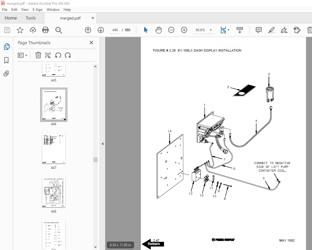
Figure # 2 28 EV-100LX Dash Display Installation 254
Figure # 3 1 Hydraulic Schematic 256
Figure # 3 2 Hydraulic Schematic Symbols 257
Figure # 3 3 Auxiliary Pump and Reservoir Assembly 258
Figure # 3 4 Auxiliary Control Valve Assembly 260
Figure # 3 5 Auxiliary Pump and Motor Assembly 262
Figure # 3 6 Auxiliary Pump Assembly 264
Figure # 3 7 Hydraulic Reservoir Assembly 266
Figure # 3 8 Torque Generator Assembly 268
Figure # 3 9 Two Stage Mast Hydraulic Assembly 270
Figure # 3 10 Three Stage Mast Hydraulic Assembly 272
Figure # 3 11 Tilt Cylinder and Related Parts 274
Figure # 3 12 Tilt Cylinder Assembly 276
Figure # 3 13 Sideshifter Cylinder with Tilt Assembly 278
Figure # 3 14 Sideshifter Manifold Valve Assembly 280
Figure # 3 15 Lift Pump and Reservoir Assembly 282
Figure # 3 16 Lift Pump Motor Assembly 284
Figure # 3 17 Lift Pump Assembly, 24 Volt 286
Figure # 3 18 Lift Pump Assembly, 36 Volt 288
Figure # 3 19 Lift Control Valve Assembly 290
Figure # 3 20 Two Stage Cylinder and Reservoir Assembly 292
Figure # 3 21 Two Stage Cylinder Assembly 294
Figure # 3 22 Three Stage Cylinder and Reservoir Assembly 296
Figure # 3 23 Three Stage Staging Cylinder Assembly 298
Figure # 3 24 Three Stage Freelift Cylinder Assembly 300
Figure # 4 1 Shielding Assembly 302
Figure # 4 2 Emergency Disconnect Assembly 304
Figure # 4 3 Auxiliary Control Assembly 306
Figure # 4 4 Hand Lift/Lower and Speed Control 308
Figure # 4 5 Forward Steering Control Assembly 310
Figure # 4 6 Rearward Steering Control Assembly 312
Figure # 4 7 Auxiliary Pump and Motor Installation 314
Figure # 4 8 Main Frame and Load Wheel Assembly 316
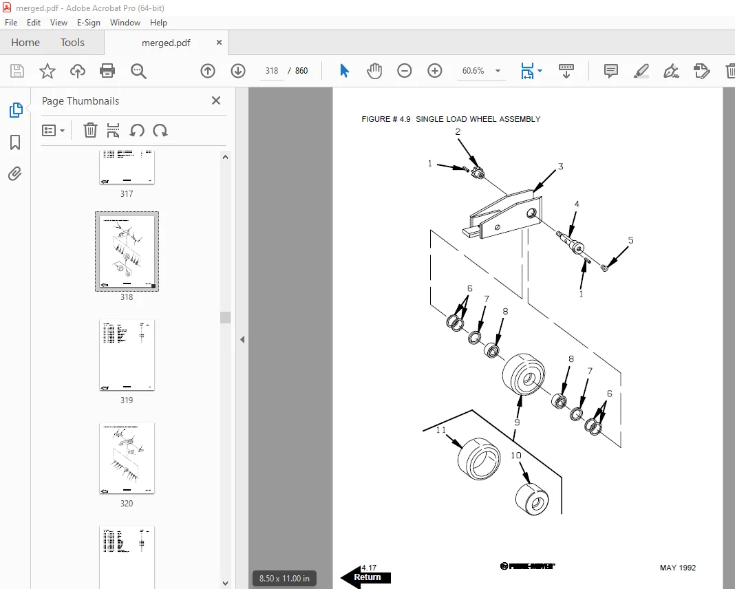
Figure # 4 9 Single Load Wheel Assembly 318
Figure # 4 10 5″ High Articulating Load Wheel Assembly 320
Figure # 4 11 4″ High Articulating Load Wheel Assembly 322
Figure # 4 12 Caster Assembly 324
Figure # 5 1 Two Stage Mast Installation 326
Figure # 5 2 Two Stage Inner Column Assembly 328
Figure # 5 3 Two Stage Outer Column Assembly 330
Figure # 5 4 Two Stage Cylinder Installation 332
Figure # 5 5 Two Stage Lift Frame Assembly 334
Figure # 5 6 Two Stage Sideshifter Assembly 336
Figure # 5 7 Two Stage Fork Assembly 338
Figure # 5 8 Three Stage Mast Installation 340
Figure # 5 9 Three Stage Inner Column Assembly 342
Figure # 5 10 Three Stage Freelift Cylinder Installation 344
Figure # 5 11 Three Stage Intermediate Column Assembly 346
Figure # 5 12 Three Stage Outer Column Assembly 348
Figure # 5 13 Three Stage Lift Frame Assembly 350
Figure # 5 14 Three Stage Sideshifter Assembly 352
Figure # 5 15 Three Stage Fork Assembly 354
Figure # 7 1 Battery Lift Interrupt “E” EV-100LX SCR Electrical Schematic 356
Figure # 7 2 Battery Lift Interrupt “E” EV-100LX SCR Electrical Schematic Symbols 357
Figure # 7 3 Battery Lift Interrupt “EE” EV-100LX SCR Electrical Schematic 358
Figure # 7 4 Battery Lift Interrupt “EE” EV-100LX SCR Electrical Schematic Symbols 359
Figure # 7 5 Battery Lift Interrupt Installation 360
Figure # 10 1 Special Tools and Lubrications 362
Numerical Index 365
Back Cover 382
Front Cover 383
Parts Ordering Instructions 384
Field Modifications 384
General Information 385
Alphabetical Index 386
Figure # 0 1 Decals and Parts Assembly 390
Figure # 1 1 Transmission and Drive Motor Installation 392
Figure # 1 2 Drive Motor and Brake Assembly 394
Figure # 1 3 Transmission Assembly Part #1 396
Figure # 1 4 Transmission Assembly Part #2 398
Figure # 2 1 “E” EV-100LX SCR Electrical Schematic 400
Figure # 2 2 “E” EV-100LX SCR Electrical Schematic Symbols 401
Figure # 2 3 “EE” EV-100LX SCR Electrical Schematic 402
Figure # 2 4 “EE” EV-100LX SCR Electrical Schematic Symbols 403
Figure # 2 5 Wiring Assembly for Cold Storage 404
Figure # 2 6 Wiring Harness Assembly 406
Figure # 2 7 Limit Switch Wiring Assembly 408
Figure # 2 8 Two Stage Mast Cable Assembly 410
Figure # 2 9 Three Stage Mast Cable Assembly 412
Figure # 2 10 Tilt with Sideshifter Cable Assembly 414
Figure # 2 11 EV-100LX Power Component Wiring 416
Figure # 2 12 EV-100LX TX & TT SCR Control Panel Assembly 418
Figure # 2 13 EV-100LX Contactor Panel Assembly & Related Parts for “E” and “EE” 420
Figure # 2 14 EV-100LX Contactor Panel Assembly 422
Figure # 2 15 EV-100LX SCR Forward & Rearward Contactor Assembly 424
Figure # 2 16 EV-100LX SCR 1A Contactor Assembly 426
Figure # 2 17 Lift Pump Contactor Assembly 428
Figure # 2 18 EV-100LX SCR Auxiliary Pump Contactor Assembly 430
Figure # 2 19 Power Connector Assembly 432
Figure # 2 20 Lift Pump Motor Assembly 434
Figure # 2 21 Drive Motor Assembly 436
Figure # 2 22 Auxiliary Pump Motor Assembly 438
Figure # 2 23 Warning Light Assembly 440
Figure # 2 24 “E” EV-100LX TT SCR Electrical Schematic 442
Figure # 2 25 “E” EV-100LX TT SCR Electrical Schematic Symbols 443
Figure # 2 26 “EE” EV-100LX TT SCR Electrical Schematic 444
Figure # 2 27 “EE” EV-100LX TT SCR Electrical Schematic Symbols 445
Figure # 2 28 EV-100LX Dash Display Installation 446
Figure # 2 29 EV-100LX SCR Electrical Schematic – 3 Function Control Handle 448
Figure # 2 30 EV-100LX SCR Electrical Schematic Symbols 449
Figure # 2 31 Wiring Harness Assembly for 3 Function Control Valve 450
Figure # 3 1 Hydraulic Schematic 452
Figure # 3 2 Hydraulic Schematic Symbols 453
Figure # 3 3 Auxiliary Pump and Reservoir Assembly 454
Figure # 3 4 Auxiliary Control Valve Assembly 456
Figure # 3 5 Auxiliary Pump and Motor Assembly 458
Figure # 3 6 Auxiliary Pump Assembly 460
Figure # 3 7 Hydraulic Reservoir Assembly 462
Figure # 3 8 Torque Generator Assembly 464
Figure # 3 9 Two Stage Mast Hydraulic Assembly 466
Figure # 3 10 Three Stage Mast Hydraulic Assembly 468
Figure # 3 11 Tilt Cylinder and Related Parts 470
Figure # 3 12 Tilt Cylinder Assembly 472
Figure # 3 13 Sideshifter Cylinder with Tilt Assembly 474
Figure # 3 14 Sideshifter Manifold Valve Assembly 476
Figure # 3 15 Lift Pump and Reservoir Assembly 478
Figure # 3 16 Lift Pump Motor Assembly 480
Figure # 3 17 Lift Pump Assembly, 24 Volt 482
Figure # 3 18 Lift Pump Assembly, 36 Volt 484
Figure # 3 19 Lift Control Valve Assembly 486
Figure # 3 20 Two Stage Cylinder and Reservoir Assembly 488
Figure # 3 21 Two Stage Cylinder Assembly 490
Figure # 3 22 Three Stage Cylinder and Reservoir Assembly 492
Figure # 3 23 Three Stage Staging Cylinder Assembly 494
Figure # 3 24 Three Stage Freelift Cylinder Assembly 496
Figure # 3 25 Hydraulic Schematic for 3 Function Control Handle 498
Figure # 3 26 Hydraulic Schematic Symbols 499
Figure # 3 27 Auxiliary Pump & Reservoir Assembly for 3 Function Control Handle 500
Figure # 3 28 Valve Assembly 502
Figure # 3 29 Two Stage Mast Hydraulic Assembly 504
Figure # 3 30 Three Stage Mast Hydraulic Assembly 506
Figure # 4 1 Shielding Assembly 508
Figure # 4 2 Emergency Disconnect Assembly 510
Figure # 4 3 Auxiliary Control Assembly 512
Figure # 4 4 Hand Lift/Lower and Speed Control 514
Figure # 4 5 Forward Steering Control Assembly 516
Figure # 4 6 Rearward Steering Control Assembly 518
Figure # 4 7 Auxiliary Pump and Motor Installation 520
Figure # 4 8 Main Frame and Load Wheel Assembly 522
Figure # 4 9 Single Load Wheel Assembly 524
Figure # 4 10 5″ High Articulating Load Wheel Assembly 526
Figure # 4 11 4″ High Articulating Load Wheel Assembly 528
Figure # 4 12 Caster Assembly 530
Figure # 4 13 Hand Lift/Lower and Speed Control for 3 Function Control 532
Figure # 5 1 Two Stage Mast Installation 534
Figure # 5 2 Two Stage Inner Column Assembly 536
Figure # 5 3 Two Stage Outer Column Assembly 538
Figure # 5 4 Two Stage Cylinder Installation 540
Figure # 5 5 Two Stage Lift Frame Assembly 542
Figure # 5 6 Two Stage Sideshifter Assembly 544
Figure # 5 7 Two Stage Fork Assembly 546
Figure # 5 8 Three Stage Mast Installation 548
Figure # 5 9 Three Stage Inner Column Assembly 550
Figure # 5 10 Three Stage Freelift Cylinder Installation 552
Figure # 5 11 Three Stage Intermediate Column Assembly 554
Figure # 5 12 Three Stage Outer Column Assembly 556
Figure # 5 13 Three Stage Lift Frame Assembly 558
Figure # 5 14 Three Stage Sideshifter Assembly 560
Figure # 5 15 Three Stage Fork Assembly 562
Figure # 6 1 Manlift EV-100 LX SCR Electrical Schematic 564
Figure # 6 2 Manlift EV-100 LX SCR Electrical Schematic Symbols 565
Figure # 6 3 Manlift Wiring Harness Assembly 566
Figure # 6 4 Manlift Three Stage Mast Cable Assembly 568
Figure # 6 5 Manlift Reach and Platform Cable Assembly 570
Figure # 6 6 Manlift Power Component Wiring 572
Figure # 6 7 Manlift Connector Assembly 574
Figure # 6 8 Manlift Hydraulic Schematic 576
Figure # 6 9 Manlift Hydraulic Schematic Symbols 577
Figure # 6 10 Manlift Hydraulic Diagram 578
Figure # 6 11 Blocking Manlift Valve Assembly 580
Figure # 6 12 Manlift Valve Assembly 582
Figure # 6 13 Manlift Load Backrest Installation 584
Figure # 7 1 Battery Lift Interrupt “E” EV-100LX SCR Electrical Schematic 586
Figure # 7 2 Battery Lift Interrupt “E” EV-100LX SCR Electrical Schematic Symbols 587
Figure # 7 3 Battery Lift Interrupt “EE” EV-100LX SCR Electrical Schematic 588
Figure # 7 4 Battery Lift Interrupt “EE” EV-100LX SCR Electrical Schematic Symbols 589
Figure # 7 5 Battery Lift Interrupt Installation 590
Figure # 10 1 Special Tools and Lubrications 592
Numerical Index 595
Back Cover 612
Front Cover 613
Parts Ordering Instructions 614
Field Modifications 614
General Information 615
Alphabetical Index 616
Figure # 0 1 Decals and Parts Assembly 620
Figure # 1 1 Transmission and Drive Motor Installation 622
Figure # 1 2 Drive Motor and Brake Assembly 624
Figure # 1 3 Transmission Assembly Part #1 626
Figure # 1 4 Transmission Assembly Part #2 628
Figure # 2 1 “E” EV-100LX SCR Electrical Schematic 630
Figure # 2 2 “E” EV-100LX SCR Electrical Schematic Symbols 631
Figure # 2 3 “EE” EV-100LX SCR Electrical Schematic 632
Figure # 2 4 “EE” EV-100LX SCR Electrical Schematic Symbols 633
Figure # 2 5 Wiring Assembly for Cold Storage 634
Figure # 2 6 Wiring Harness Assembly 636
Figure # 2 7 Limit Switch Wiring Assembly 638
Figure # 2 8 Two Stage Mast Cable Assembly 640
Figure # 2 9 Three Stage Mast Cable Assembly 642
Figure # 2 10 Tilt with Sideshifter Cable Assembly 644
Figure # 2 11 EV-100LX Power Component Wiring 646
Figure # 2 12 EV-100LX TX & TT SCR Control Panel Assembly 648
Figure # 2 13 EV-100LX Contactor Panel Assembly & Related Parts for “E” and “EE” 650
Figure # 2 14 EV-100LX Contactor Panel Assembly 652
Figure # 2 15 EV-100LX SCR Forward & Rearward Contactor Assembly 654
Figure # 2 16 EV-100LX SCR 1A Contactor Assembly 656
Figure # 2 17 Lift Pump Contactor Assembly 658
Figure # 2 18 EV-100LX SCR Auxiliary Pump Contactor Assembly 660
Figure # 2 19 Power Connector Assembly 662
Figure # 2 20 Lift Pump Motor Assembly 664
Figure # 2 20A Lift Pump Motor Assembly, 36 Volt G E 666
Figure # 2 21 Drive Motor Assembly 668
Figure # 2 22 Auxiliary Pump Motor Assembly 670
Figure # 2 23 Warning Light Assembly 672
Figure # 2 24 “E” EV-100LX TT SCR Electrical Schematic 674
Figure # 2 25 “E” EV-100LX TT SCR Electrical Schematic Symbols 675
Figure # 2 26 “EE” EV-100LX TT SCR Electrical Schematic 676
Figure # 2 27 “EE” EV-100LX TT SCR Electrical Schematic Symbols 677
Figure # 2 28 EV-100LX Dash Display Installation 678
Figure # 2 29 EV-100LX SCR Electrical Schematic – 3 Function Control Handle 680
Figure # 2 30 EV-100LX SCR Electrical Schematic Symbols 681
Figure # 2 29A EV-100LX SCR Electrical Schematic – 3 Function Control Handle 682
Figure # 2 30A EV-100LX SCR Electrical Schematic Symbols 683
Figure # 2 31 Wiring Harness Assembly for 3 Function Control Valve 684
Figure # 3 1 Hydraulic Schematic 686
Figure # 3 2 Hydraulic Schematic Symbols 687
Figure # 3 3 Auxiliary Pump and Reservoir Assembly 688
Figure # 3 4 Auxiliary Control Valve Assembly 690
Figure # 3 5 Auxiliary Pump and Motor Assembly 692
Figure # 3 6 Auxiliary Pump Assembly 694
Figure # 3 7 Hydraulic Reservoir Assembly 696
Figure # 3 8 Torque Generator Assembly 698
Figure # 3 9 Two Stage Mast Hydraulic Assembly 700
Figure # 3 10 Three Stage Mast Hydraulic Assembly 702
Figure # 3 11 Tilt Cylinder and Related Parts 704
Figure # 3 12 Tilt Cylinder Assembly 706
Figure # 3 13 Sideshifter Cylinder with Tilt Assembly 708
Figure # 3 14 Sideshifter Manifold Valve Assembly 710
Figure # 3 15 Lift Pump and Reservoir Assembly 712
Figure # 3 16 Lift Pump Motor Assembly 714
Figure # 3 17 Lift Pump Assembly 716
Figure # 3 18 Lift Pump Motor Assembly, 36 Volt “E” 718
Figure # 3 19 Lift Control Valve Assembly 720
Figure # 3 20 Two Stage Cylinder and Reservoir Assembly 722
Figure # 3 21 Two Stage Cylinder Assembly 724
Figure # 3 22 Three Stage Cylinder and Reservoir Assembly 726
Figure # 3 23 Three Stage Staging Cylinder Assembly 728
Figure # 3 24 Three Stage Freelift Cylinder Assembly 730
Figure # 3 25 Hydraulic Schematic for 3 Function Control Handle 732
Figure # 3 26 Hydraulic Schematic Symbols 733
Figure # 3 27 Auxiliary Pump & Reservoir Assembly for 3 Function Control Handle 734
Figure # 3 28 Valve Assembly 736
Figure # 3 29 Two Stage Mast Hydraulic Assembly 738
Figure # 3 30 Three Stage Mast Hydraulic Assembly 740
Figure # 4 1 Shielding Assembly 742
Figure # 4 2 Emergency Disconnect Assembly 744
Figure # 4 3 Auxiliary Control Assembly 746
Figure # 4 4 Hand Lift/Lower and Speed Control 748
Figure # 4 5 Forward Steering Control Assembly 750
Figure # 4 6 Rearward Steering Control Assembly 752
Figure # 4 7 Auxiliary Pump and Motor Installation 754
Figure # 4 8 Main Frame and Load Wheel Assembly 756
Figure # 4 9 Single Load Wheel Assembly 758
Figure # 4 9A Single Load Wheel Assembly 760
Figure # 4 10 5″ High Articulating Load Wheel Assembly 762
Figure # 4 10A 5″ High Articulating Load Wheel Assembly 764
Figure # 4 11 4″ High Articulating Load Wheel Assembly 766
Figure # 4 12 Caster Assembly 768
Figure # 4 13 Hand Lift/Lower and Speed Control for 3 Function Control 770
Figure # 5 1 Two Stage Mast Installation 772
Figure # 5 2 Two Stage Inner Column Assembly 774
Figure # 5 3 Two Stage Outer Column Assembly 776
Figure # 5 4 Two Stage Cylinder Installation 778
Figure # 5 5 Two Stage Lift Frame Assembly 780
Figure # 5 6 Two Stage Sideshifter Assembly 782
Figure # 5 7 Two Stage Fork Assembly 784
Figure # 5 8 Three Stage Mast Installation 786
Figure # 5 9 Three Stage Inner Column Assembly 788
Figure # 5 10 Three Stage Freelift Cylinder Installation 790
Figure # 5 11 Three Stage Intermediate Column Assembly 792
Figure # 5 12 Three Stage Outer Column Assembly 794
Figure # 5 13 Three Stage Lift Frame Assembly 796
Figure # 5 14 Three Stage Sideshifter Assembly 798
Figure # 5 15 Three Stage Fork Assembly 800
Figure # 6 1 Remote Lift/Lower EV-100 LX SCR Electrical Schematic 802
Figure # 6 2 Remote Lift/Lower EV-100 LX SCR Electrical Schematic Symbols 803
Figure # 6 3 Remote Lift/Lower Wiring Harness Assembly 804
Figure # 6 4 Remote Lift/Lower Three Stage Mast Cable Assembly 806
Figure # 6 5 Remote Lift/Lower Reach and Platform Cable Assembly 808
Figure # 6 6 Remote Lift/Lower Power Component Wiring 810
Figure # 6 7 Remote Lift/Lower Connector Assembly 812
Figure # 6 8 Remote Lift/Lower Hydraulic Schematic 814
Figure # 6 9 Remote Lift/Lower Manlift Hydraulic Schematic Symbols 815
Figure # 6 10 Remote Lift/Lower Hydraulic Diagram 816
Figure # 6 11 Blocking Remote Lift/Lower Valve Assembly 818
Figure # 6 12 Remote Lift/Lower Valve Assembly 820
Figure # 6 13 Remote Lift/Lower Load Backrest Installation 822
Figure # 6 14 Remote Lift/Lower Contactor Assembly 824
Figure # 7 1 Battery Lift Interrupt “E” EV-100LX SCR Electrical Schematic 826
Figure # 7 2 Battery Lift Interrupt “E” EV-100LX SCR Electrical Schematic Symbols 827
Figure # 7 1A Battery Lift Interrupt “E” for 3 Function Control Handle 828
Figure # 7 2A Battery Lift Interrupt “E” EV-100LX SCR Electrical Schematic Symbols 829
Figure # 7 3 Battery Lift Interrupt “EE” EV-100LX SCR Electrical Schematic 830
Figure # 7 4 Battery Lift Interrupt “EE” EV-100LX SCR Electrical Schematic Symbols 831
Figure # 7 3A Battery Lift Interrupt “EE” for 3 Function Control Handle 832
Figure # 7 4A Battery Lift Interrupt “EE” EV-100LX SCR Electrical Schematic Symbols 833
Figure # 7 5 Battery Lift Interrupt Installation 834
Figure # 10 1 Special Tools and Lubrications 836
Numerical Index 839
Back Cover 860
DESCRIPTION:
BT Prime-Mover RS-40C Straddle Truck Parts Manual SN RS40C170373 – PDF DOWNLOAD
PARTS ORDERING INSTRUCTIONS:
HOW TO ORDER:
- When you order, supply the part number, quantity, model and serial numbers of your machine. Supplying this information will assure prompt, efficient handling of your order. The pictorial reference number is not needed and including it can only add confusion.
- Since your dealer carries many parts in stock and maintains up-to-date prices on all parts, he will be able to process your order immediately. If, for some reason, the part is not in stock, he will order it from the factory. In either event, he maintains a current file of service manuals, which give all available parts ordering or technical information.
- All prices are FOB factory in Muscatine, Iowa. Shipping charges are added to the price of the part shipping from the factory.
WHERE TO ORDER:
Always order parts from the dealer who sold you your Prime-Mover. If it is necessary for the dealer to order parts from the factory, he is able to get prompt service for you. Parts are shipped in accordance with shipping instructions given on the order.
S.V 01/02/2025