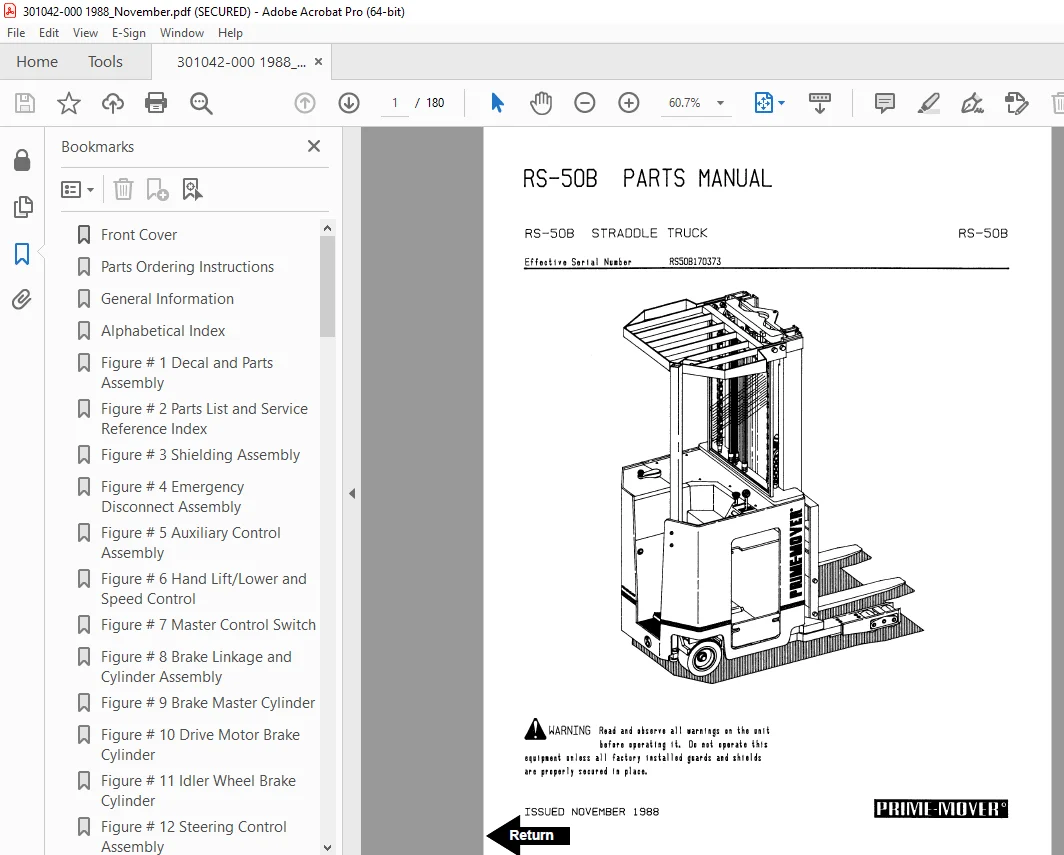
BT Prime-Mover RS-50B Straddle Truck Parts Manual_1988 SN RS508170373 PDF
$27.95
BT Prime-Mover RS-50B Straddle Truck Parts Manual_1988 SN RS508170373 – PDF DOWNLOAD
Description
BT Prime-Mover RS-50B Straddle Truck Parts Manual_1988 SN RS508170373 – PDF DOWNLOAD
FILE DETAILS:
BT Prime-Mover RS-50B Straddle Truck Parts Manual_1988 SN RS508170373 – PDF DOWNLOAD
Language : English
Pages : 180
Downloadable : Yes
File Type : PDF
IMAGES PREVIEW OF THE MANUAL:
TABLE OF CONTENTS:
BT Prime-Mover RS-50B Straddle Truck Parts Manual_1988 SN RS508170373 – PDF DOWNLOAD
Front Cover 1
Parts Ordering Instructions 2
General Information 3
Alphabetical Index 4
Figure # 1 Decal and Parts Assembly 6
Figure # 2 Parts List and Service Reference Index 8
Figure # 3 Shielding Assembly 10
Figure # 4 Emergency Disconnect Assembly 12
Figure # 5 Auxiliary Control Assembly 14
Figure # 6 Hand Lift/Lower and Speed Control 16
Figure # 7 Master Control Switch 18
Figure # 8 Brake Linkage and Cylinder Assembly 20
Figure # 9 Brake Master Cylinder 22
Figure # 10 Drive Motor Brake Cylinder 24
Figure # 11 Idler Wheel Brake Cylinder 26
Figure # 12 Steering Control Assembly 28
Figure # 13 Auxiliary Pump Assembly 30
Figure # 14 Auxiliary Motor Assembly 32
Figure # 15 Transmission and Steering Installation 34
Figure # 16 Drive Motor and Brake Assembly 36
Figure # 17 Drive Motor Assembly 38
Figure # 18 Transmission Assembly Part # 1 40
Figure # 19 Transmission Assembly Part # 2 42
Figure # 20 Idler Wheel Installation 44
Figure # 21 Idler Wheel Assembly 46
Figure # 22 EV-100 Electrical Schematic 48
Figure # 23 Electrical Schematic Symbols 49
Figure # 24 Wiring Assembly for Cold Storage 50
Figure # 25 Wiring Harness Assembly 52
Figure # 26 Limit Switch Wiring Harness Assembly 54
Figure # 27 Two Stage Mast Cable Assembly 56
Figure # 28 Three Stage Mast Cable Assembly 58
Figure # 29 Tilt with Sideshifter Cable Assembly 60
Figure # 30 Power Component Wiring 62
Figure # 31 EV-100 SCR Contactor Panel Assembly 64
Figure # 32 EV-100 SCR Control 66
Figure # 33 EV-100 Forward & Rearward Contactor Assembly 68
Figure # 34 EV-100 Lift Pumps and 1A Contactor Assembly 70
Figure # 35 EV-100 Steering Contactor Assembly 72
Figure # 36 Connector Assembly 74
Figure # 37 Warning Light Assembly 76
Figure # 38 Hydraulic Schematic 78
Figure # 39 Hydraulic Schematic Symbols 79
Figure # 40 Auxiliary Pump and Reservoir Assembly 80
Figure # 41 Auxiliary Control Valve Assembly 82
Figure # 42 Hydraulic Reservoir Assembly 84
Figure # 43 Steering Control Valve and Hose Assembly 86
Figure # 44 Steering Control Valve Assembly 88
Figure # 45 Steering Cylinder Assembly 90
Figure # 46 Two Stage Mast Hydraulic Assembly 92
Figure # 47 Three Stage Mast Hydraulic Assembly 94
Figure # 48 Tilt Cylinder and Related Parts 96
Figure # 49 Tilt Cylinder Assembly 98
Figure # 50 Sideshifter Cylinder with Tilt Assembly 100
Figure # 51 Sideshifter Cylinder Assembly 102
Figure # 52 Sideshifter Manifold Valve Assembly 104
Figure # 53 Lift Pump and Reservoir Assembly 106
Figure # 54 Lift Pump and Motor Assembly 108
Figure # 54 1 Lift Pump and Motor Assembly 110
Figure # 55 24 Volt Lift Pump Assembly 112
Figure # 56 36 Volt Lift Pump Assembly 114
Figure # 57 Lift Motor Assembly 116
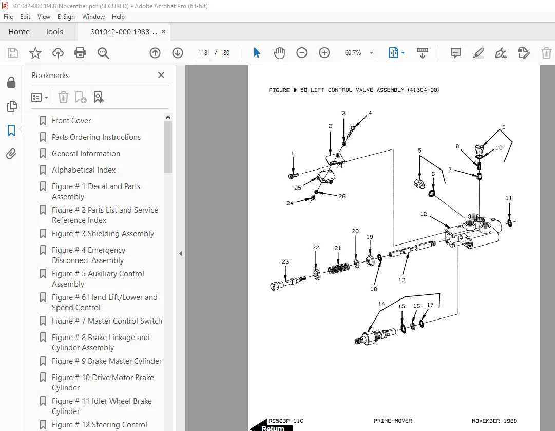
Figure # 58 Lift Control Valve Assembly 118
Figure # 59 Two Stage Cylinder and Reservoir Assembly 120
Figure # 60 Two Stage Cylinder Assembly 122
Figure # 61 Three Stage Cylinder and Reservoir Assembly 124
Figure # 62 Three Stage Staging Cylinder Assembly 126
Figure # 63 Three Stage Freelift Cylinder Assembly 128
Figure # 64 Two Stage Mast Installation 130
Figure # 65 Two Stage Inner Column Assembly 132
Figure # 66 Two Stage Outer Column Assembly 134
Figure # 67 Two Stage Cylinder Installation 136
Figure # 68 Lift Frame Assembly 138
Figure # 69 Sideshifter Assembly 140
Figure # 70 Fork Assembly 142
Figure # 71 Three Stage Mast Installation 144
Figure # 72 Three Stage Outer Column Assembly 146
Figure # 73 Three Stage Intermediate Column Assembly 148
Figure # 74 Three Stage Inner Column Assembly 150
Figure # 75 Three Stage Freelift Cylinder Installation 152
Figure # 76 Main Frame and Load Wheel Assembly 154
Figure # 77 Single Load Wheel Assembly 156
Figure # 78 5″ High Articulating Load Wheel Assembly 158
Figure # 79 4″ High Articulating Load Wheel 160
Figure # 80 Special Tools and Lubrications 162
Numerical Index 164
DESCRIPTION:
BT Prime-Mover RS-50B Straddle Truck Parts Manual_1988 SN RS508170373 – PDF DOWNLOAD
PARTS ORDERING INSTRUCTIONS:
HOW TO ORDER:
- When you order, supply the part number, quantity, model and serial numbers of your machine. Supplying this information will assure prompt, efficient handling of your order. The pictorial reference number is not needed and including it can only add confusion.
- Since your dealer carries many parts in stock and maintains up-to-date prices on all parts, he will be able to process your order immediately. If, for some reason, the part is not in stock, he will order it from the factory. In either event, he maintains a current file of service manuals, which give all available parts ordering or technical information.
- All prices are FOB factory in Muscatine, Iowa. Shipping charges are added to the price of the part shipping from the factory.
WHERE TO ORDER
Always order parts from the dealer who sold you your Prime-Mover. If it is necessary for the dealer to order parts from the factory, he is able to get prompt service for you. Parts are shipped in accordance with shipping instructions given on the order.
S.V 21/01/2025