BT Prime-Mover SC-20 SC-25 SC-30 SC-40 SC Series Truck Operating Maintenace & Parts Manual – PDF DOWNLOAD
$28.95
BT Prime-Mover SC-20 SC-25 SC-30 SC-40 SC Series Truck Operating Maintenace & Parts Manual – PDF DOWNLOAD
Description
BT Prime-Mover SC-20 SC-25 SC-30 SC-40 SC Series Truck Operating Maintenace & Parts Manual – PDF DOWNLOAD
FILE DETAILS:
BT Prime-Mover SC-20 SC-25 SC-30 SC-40 SC Series Truck Operating Maintenace & Parts Manual – PDF DOWNLOAD
Language : English
Pages : 223
Downloadable : Yes
File Type : PDF
IMAGES PREVIEW OF THE MANUAL:
TABLE OF CONTENTS:
BT Prime-Mover SC-20 SC-25 SC-30 SC-40 SC Series Truck Operating Maintenace & Parts Manual – PDF DOWNLOAD
310681-000 1968_October
310668-000 1971_February
310564-000 1973_October
Update Memo 1977_January
301043-000 Late in the year 1980
Front Cover 2
Warranty 3
New Owners 4
Preliminary Service 4
Specifications 4
Contents 4
Operating Rules 5
Maintenance Chart 8
Lubrication Chart 9
Maintenance Instructions 10
Service and Disassembly Instructions 13
Parts Ordering Instructions 14
Figure # 1 Decal and Part Assembly 15
Figure # 2 Parts List and Service Reference Index 17
Figure # 3 Shielding Assembly 19
Figure # 4 Handle and Transmission Assembly 21
Figure # 5 Handle Assembly 23
Figure # 6 Control Switch 25
Figure # 7 Transmission Assembly Part # 1 22:1 26
Figure # 8 Transmission Assembly Part # 2 27
Figure # 9 Drive Motor Assembly 28
Figure # 10 Traction Motor 29
Figure # 11 Drive Motor 24 Volt 30
Figure # 12 Wiring Schematic SC-20/40 31
Figure # 13 Control Panel Wire Assembly Part 1 32
Figure # 14 Control Panel Wire Assembly Part 2 33
Figure # 15 Control Panel Wire Assembly Part 3 34
Figure # 16 Connector Assembly 35
Figure # 17 Control Panel Assembly 36
Figure # 18 GE Contactor Assembly 37
Figure # 19 GE Contactor Assembly 38
Figure # 20 Square D Contactor 39
Figure # 21 2nd Speed Contactor Assembly 40
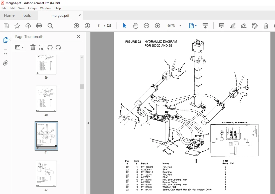
Figure # 22 Hydraulic Diagram for SC-20 and -25 41
Figure # 23 Reservoir Assembly 42
Figure # 24 Reservoir Pump and Motor 43
Figure # 25 SC-20/25 Pump and Motor Assembly 45
Figure # 26 SC-20/25 Motor Assembly 12 Volt and 24 Volt 47
Figure # 27 SC20/25 Tilt Cylinders and Related Parts 48
Figure # 28 SC20/25 Tilt Cylinder Assembly 49
Figure # 29 SC-20/25 Lift Cylinder and Related Parts 50
Figure # 30 SC-20 2″ Lift Cylinder Assembly 51
Figure # 31 SC-25 2 1/2″ Lift Cylinder Assembly 53
Figure # 32 SC-30 Hydraulic Diagram 55
Figure # 33 SC-30 Reservoir and Pump Assembly 56
Figure # 34 SC-30 Hydraulic Pump and Motor 57
Figure # 35 SC-30 Pump Assembly 58
Figure # 36 SC-30 Motor Assembly 59
Figure # 37 SC-30 Motor Assembly 60
Figure # 38 SC-30 Reservoir Assembly 61
Figure # 39 SC-30 Tilt Cylinders and Related Parts 62
Figure # 40 SC-30 Tilt Cylinder Assembly 63
Figure # 41 SC-30 Lift Cylinder and Hose Assembly 64
Figure # 42 SC-30 2 1/2″ Lift Cylinder 65
Figure # 43 SC-40 Hydraulic Diagram 67
Figure # 44 SC-40 Reservoir Pump and Motor Assembly, 24 Volt 68
Figure # 45 SC-40 Hydraulic Pump and Motor 69
Figure # 46 SC-40 Pump Assembly 70
Figure # 47 SC-40 Pump Motor Assembly 71
Figure # 48 SC-40 Motor Assembly 72
Figure # 49 SC-40 Tilt Cylinder Assembly and Related Parts 73
Figure # 50 SC-40 Tilt Cylinder Assembly 74
Figure # 51 SC-40 Lift Cylinder and Related Parts 75
Figure # 52 SC-40 2 3/4″ Lift Cylinder Assembly 76
Figure # 53 Lever and Linkage to Control Valve 77
Figure # 54 Control Valve Assembly 78
Figure # 55 SC-20, SC-25 Mast Assembly 79
Figure # 56 SC-20/25 Fork Assembly 81
Figure # 57 SC-20, SC-25 Outer Column 82
Figure # 58 SC-20, SC-25 Inner Column Assembly 83
Figure # 59 SC-20, SC-25 Lift Cylinder and Related Parts 84
Figure # 60 SC-20, SC-25 Lift Frame and Load Backrest 85
Figure # 61 SC-20 (Only) Lift Frame and Load Backrest 86
Figure # 62 SC-30 Mast Assembly 87
Figure # 63 SC-30 Fork Assembly 88
Figure # 64 SC-30 Outer Column 89
Figure # 65 SC-30 Inner Column Assembly 90
Figure # 66 SC-30 Lift Cylinder and Related Parts 91
Figure # 67 SC-30 Lift Frame and Load Backrest 92
Figure # 68 SC-40 Mast Assembly 93
Figure # 69 SC-40 Fork Assembly 94
Figure # 70 SC-40 Outer Column 95
Figure # 71 SC-40 Inner Column Assembly 96
Figure # 72 SC-40 Lift Cylinder and Related Parts 97
Figure # 73 SC-40 Lift Frame and Load Backrest 98
Figure # 74 SC-40 White Mast Assembly 99
Figure # 75 SC-40 Fork Assembly 101
Figure # 76 SC-40 White Outer Rail Assembly 102
Figure # 77 SC-40 White Intermediate Rail Assembly 103
Figure # 78 SC-40 White Inner Rail Assembly 104
Figure # 79 SC-40 White Cylinder Assembly 105
Figure # 80 SC-40 White Cylinder 106
Figure # 81 SC-40 White Carriage Assembly 107
Figure # 82 Frame Assembly 108
Figure # 83 Cold Storage of the Control Switch 109
Service Guide 110
Back Cover 113
Front Cover 114
Prime-Mover Warranty 115
To New Prime-Mover Owners 116
Contents 116
Operating Instructions 117
Preliminary Service 117
Controls 117
Safety Interlock 117
Mast Controls 117
Direction Control 117
Deadman Brake 117
Time Delay 117
Key Switch (optional) 117
Horn 118
Dynamic Brake (optional) 118
Field Weakening (optional over-speed) 118
Operator Inspection and Maintenance Procedures 118
Daily 118
Weekly 118
Semi-Annually (or as required) 118
Battery Care 118
Maintenance Instructions 118
Battery 119
Power Wiring 119
Control Wiring 119
Control Switches (handle) 119
Mechanical Brake 119
Interlock Switch 120
Transmission Rollers 120
Contactor Points 120
Motor Commutator 120
Hydraulic System 120
Service and Disassembly Instructions 120
Handle 120
Direction Control Switches 121
Transmission 121
Drive Motor 121
Drive Gear Adjustment 121
Electric Control Panel 121
Hydraulic Pump 121
Mast Assembly 121
Lift Frame 121
Inner Column 121
Tilt Cylinder 121
Hydraulic Lift Cylinder 122
Gear Case Guide Ring 122
Parts Ordering Instructions 122
How to Order 122
Where to Order 122
Instructions for Returning Parts 122
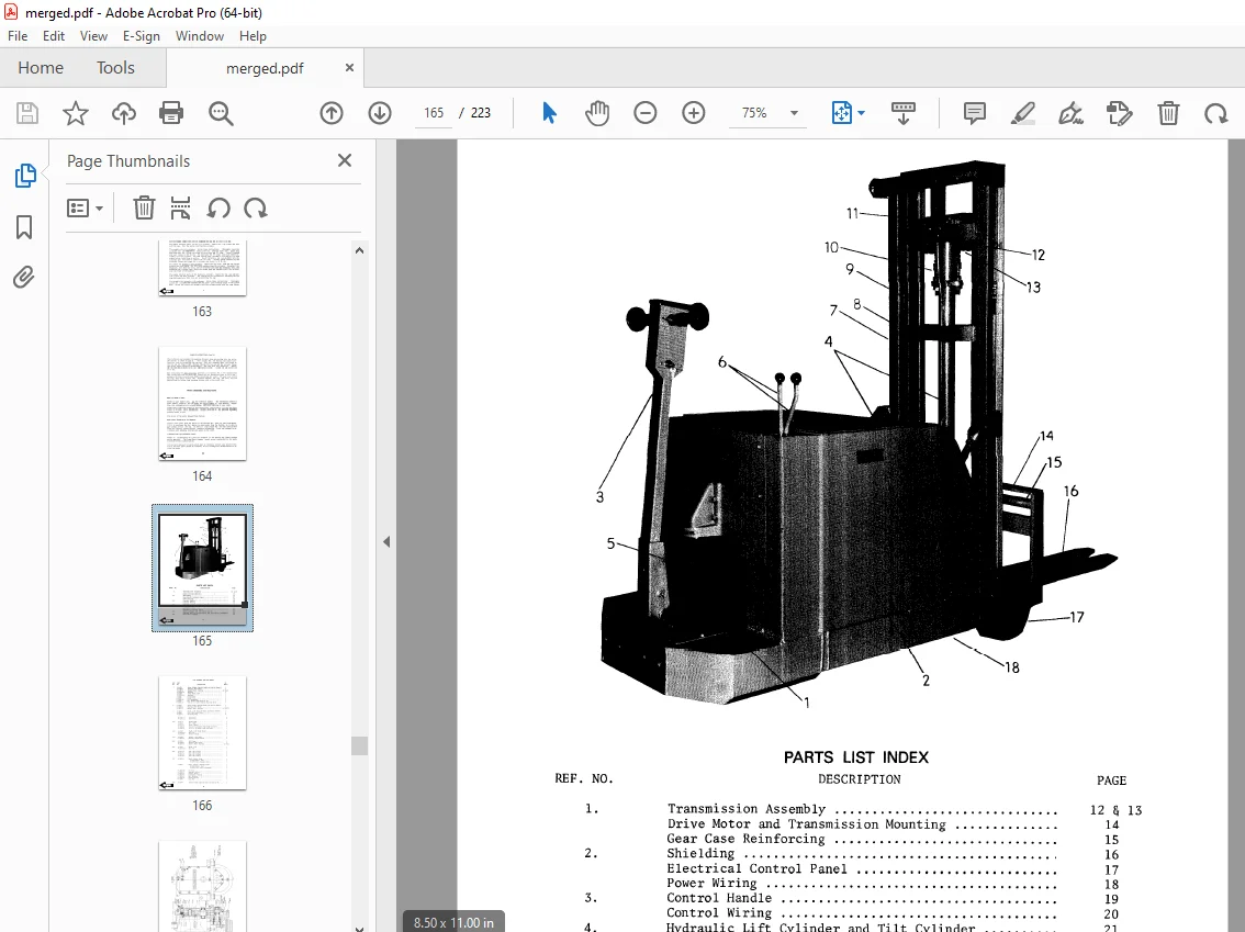
Parts List Index 123
Frame Fittings 127
Control Handle 128
Transmission Assembly 12V 132
Drive Motor Service Parts 132
Transmission Assembly 24 V 134
Drive Motor Service Parts 134
Electrical Control Panel 135
Power Wiring 136
Control Wiring 137
Hydraulic Piping Diagram 12 V 139
Hydraulic Piping Diagram 24 V 140
Tilt Cylinder 142
Hydraulic Unit Assembly 12 V 143
Hydraulic Pump and Motor 24 V 144
Lift – Tilt Linkage 145
Control Valve 146
Hydraulic Cylinder Assembly 147
Hydraulic Cylinder Assembly 148
Sheave Head 149
Service Guide 150
Back Cover 153
Front Cover 154
Prime Mover Warranty 155
Contents 156
To New Prime-Mover Owners 156
Operating Instructions 157
Preliminary Service 157
Operation 157
Safety Interlock 157
Mast Controls 157
Direction Control 157
Deadman Brake 158
Time Delay 158
Key Switch (optional) 158
Horn (optional) 158
Dynamic Brake (optional) 158
Operator Maintenance 158
Daily 158
Weekly 158
Semi-Annually (or as required) 158
Battery Care 159
Maintenance Instructions 159
Battery 159
Power Wiring 159
Control Wiring 160
Control Switches (Handle) 160
Mechanical Brake 160
Interlock Switch 161
Transmission Rollers 161
Contactor Points 161
Motor Commutator 162
Hydraulic System 162
Service Instructions 162
Handle 162
Transmission 162
Gear Case Reinforcing 162
Drive Motor 163
Control Panel 163
Hydraulic Pump Unit 163
Mast Assembly 163
Lift Frame 163
Inner Column 163
Tilt Cylinders 163
Hydraulic Lift Cylinder 163
Gear Case Ring 164
Parts Ordering Instructions 164
Parts List Index 165
Lift Assembly and Load Wheels 166
Transmission Assembly 168
Drive Motor and Transmission Mounting 169
Motor Service Parts 169
Gear Case Reinforcement 170
Shielding 171
Electrical Control Panel 172
Power Wiring 173
Control Handle 174
Control Wiring 175
Hydraulic Cylinder Assembly 176
Tilt Cylinder 176
Hydraulic Piping Diagram 177
Hydraulic Pump 178
Motor Service Parts 178
Brake Linkage and Interlock Switch 179
Control Switch Installation 180
Lift – Tilt Linkage 181
Control Valve 182
Back Cover 185
Front Cover 186
Prime Mover Warranty 187
Contents 188
To New Prime-Mover Owners 188
Operating Instructions 189
Preliminary Service 189
Operation 189
Safety Interlock 189
Mast Controls 189
Direction Control 189
Deadman Brake 190
Time Delay 190
Key Switch (optional) 190
Horn (optional) 190
Dynamic Brake (optional) 190
Operator Maintenance 190
Battery Care 191
Maintenance Instructions 191
Battery 191
Power Wiring 191
Control Wiring 192
Control Switches (handle) 192
Mechanical Brake 192
Interlock Switch 193
Transmission Rollers 193
Contactor Points 193
Motor Commutator 194
Hydraulic System 194
Service Instructions 194
Handle 194
Transmission 194
Gear Case 194
Drive Motor 195
Control Panel 195
Hydraulic Pump Unit 195
Mast Assembly 195
Lift Frame 195
Inner Column 195
Tilt Cylinders 195
Hydraulic Lift Cylinder 195
Gear Case Ring 196
Parts Ordering Instructions 196
How to Order a Part 196
How Parts Orders will be Handled 196
Instructions for Returning Parts 196
Parts List Index 197
Transmission Assembly 200
Drive Motor and Transmission Mounting 201
Gear Case Reinforcement 202
Shielding 203
Electrical Control Panel 204
Power Wiring 205
Control Handle 206
Control Wiring 207
Hydraulic Cylinder Assembly 208
Tilt Cylinder 208
Hydraulic Piping Diagram 209
Hydraulic Pump 210
Brake Linkage and Interlock Switch 211
Control Switch Installation 212
Lift – Tilt Linkage 213
Control Valve 214
Service Guide 215
DESCRIPTION:
BT Prime-Mover SC-20 SC-25 SC-30 SC-40 SC Series Truck Operating Maintenace & Parts Manual – PDF DOWNLOAD
OPERATING RULES AND INSTRUCTIONS:
OPERATOR QUALIFICATIONS
Only trained and authorized operators shall be permitted to operate a powered industrial truck. Operators of powered industrial trucks shall be qualified as to visual, auditory, physical, and mental ab 巾ty to operate the equipment.
OPERATOR TRAINING
An effective operator training program should center around user company’s policies, operating conditions and trucks. The program should be presented completely to all new operators and not condensed for those claiming previous experience.
OPERATOR RESPONSIBILITY
Powered industrial truck operators shall abide by the following rules and practices.
GENERAL RULES AND PRACTICES
A. Safeguard the pedestrians at all times. Do not drive a truck up to anyone standing in front of a bench or other fixed object.
B. Do not allow anyone to stand or pass under the elevated portion of any truck, whether loaded or empty.
C. Unauthorized passengers shaJJ not be permitted to ride.
D. Do not put any part of the body between the uprights of the mast or outside the running lines of the truck.
E. When the operator is dismounted and within 25 feet (7600mm) of the truck which remains in his view, the load engaging means shall be fully lowered, controls neutralized and brakes set to prevent movement.
F. A powered industrial truck is unattended when the operator is 25 feet (7600mm) or more from the truck which remains in view, or whenever the operator leaves the truck and it is not in his view.
S.V 30/01/2025