BT Prime Mover SC-30 Electrical Counter Balanced Walkie Stacker Parts Manual PDF
$20.95
BT Prime Mover SC-30 Electrical Counter Balanced Walkie Stacker Parts Manual – PDF DOWNLOAD
Description
BT Prime Mover SC-30 Electrical Counter Balanced Walkie Stacker Parts Manual – PDF DOWNLOAD
FILE DETAILS:
BT Prime Mover SC-30 Electrical Counter Balanced Walkie Stacker Parts Manual – PDF DOWNLOAD
Language : English
Pages : 83
Downloadable : Yes
File Type : PDF
IMAGES PREVIEW OF THE MANUAL:
TABLE OF CONTENTS:
BT Prime Mover SC-30 Electrical Counter Balanced Walkie Stacker Parts Manual – PDF DOWNLOAD
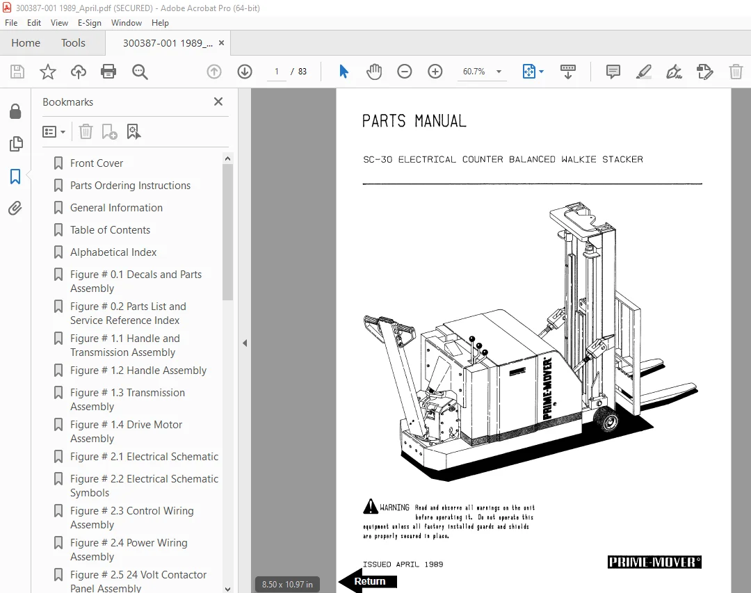
Front Cover 1
Parts Ordering Instructions 2
General Information 3
Table of Contents 4
Alphabetical Index 5
Figure # 0 1 Decals and Parts Assembly 6
Figure # 0 2 Parts List and Service Reference Index 8
Figure # 1 1 Handle and Transmission Assembly 10
Figure # 1 2 Handle Assembly 12
Figure # 1 3 Transmission Assembly 14
Figure # 1 4 Drive Motor Assembly 16
Figure # 2 1 Electrical Schematic 18
Figure # 2 2 Electrical Schematic Symbols 19
Figure # 2 3 Control Wiring Assembly 20
Figure # 2 4 Power Wiring Assembly 22
Figure # 2 5 24 Volt Contactor Panel Assembly 24
Figure # 2 6 Contactor Assembly, 24 Volt 26
Figure # 2 7 Forward & Rearward Contactor Assembly, 24 Volt 28
Figure # 2 8 Power Connector Assembly 30
Figure # 2 9 Drive Motor Assembly 32
Figure # 2 10 Pump Motor Assembly 34
Figure # 2 11 Master Control Switch 36
Figure # 3 1 Hydraulic Schematic 38
Figure # 3 2 Hydraulic Schematic Symbols 39
Figure # 3 3 Reservoir and Pump Assembly 40
Figure # 3 4 Reservoir Assembly 42
Figure # 3 5 Pump and Motor Assembly 44
Figure # 3 6 Pump Assembly 46
Figure # 3 7 Control Spool Valve Assembly 48
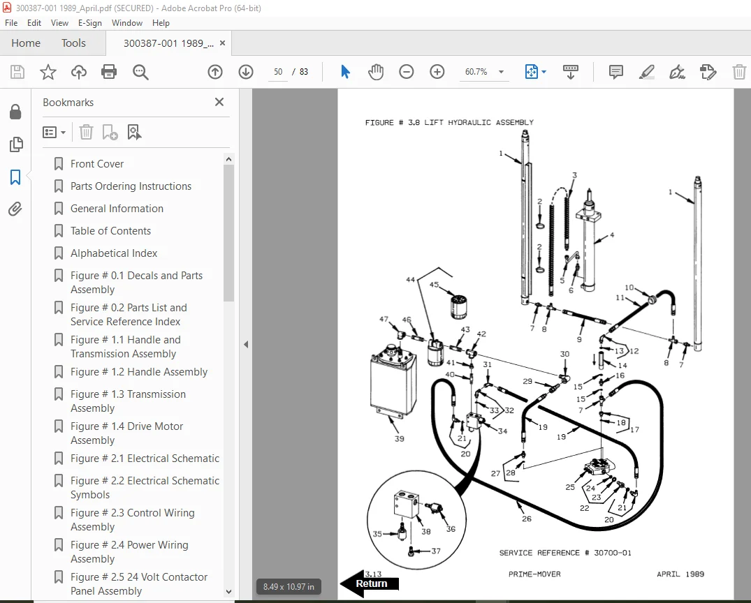
Figure # 3 8 Lift Hydraulic Assembly 50
Figure # 3 9 Cylinder Assembly 52
Figure # 3 10 Cylinder Assembly 54
Figure # 3 11 Sideshifter Hydraulic Assembly 56
Figure # 3 12 Tilt Cylinder and Related Parts 58
Figure # 3 13 Tilt Cylinder Assembly 60
Figure # 4 1 Frame Assembly 62
Figure # 4 2 Handle and Linkage for Control Valve 64
Figure # 4 3 Shield Assembly 66
Figure # 5 1 Two Stage Full Freelift Mast Installation 68
Figure # 5 2 Outer Column Assembly 70
Figure # 5 3 Inner Column Assembly 72
Figure # 5 4 Freelift Cylinder Assembly and Related Parts 74
Figure # 5 5 Lift Frame and Backrest Assembly 76
Figure # 5 6 Sideshifter Assembly 78
Figure # 5 7 Fork Assembly 80
Figure # 6 1 Special Tools and Lubrications 82
S.V 20/01/2025