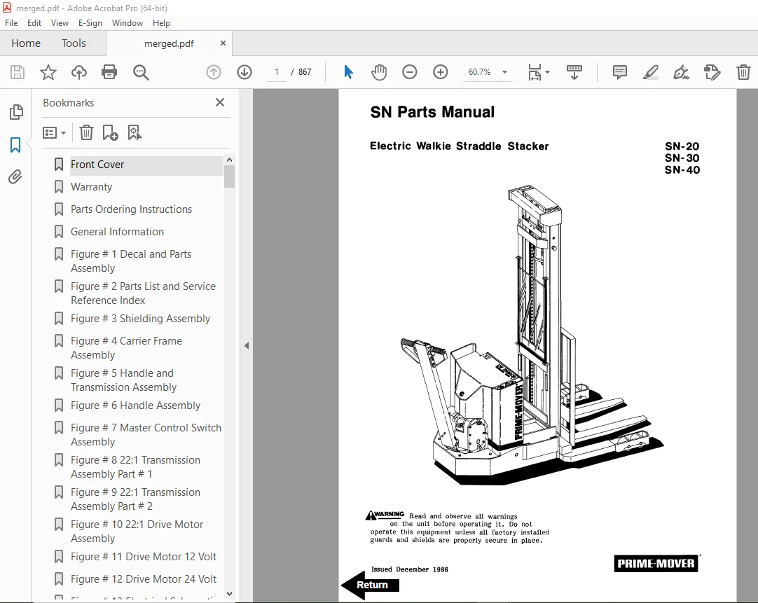
BT Prime Mover SN Series SN20 SN30 SN40 Electric Walkie Straddle Stacker Parts Manual PDF
$33.95
BT Prime Mover SN Series SN20 SN30 SN40 Electric Walkie Straddle Stacker Parts Manual – PDF DOWNLOAD
Description
BT Prime Mover SN Series SN20 SN30 SN40 Electric Walkie Straddle Stacker Parts Manual – PDF DOWNLOAD
FILE DETAILS:
BT Prime Mover SN Series SN20 SN30 SN40 Electric Walkie Straddle Stacker Parts Manual – PDF DOWNLOAD
Language : English
Pages : 867
Downloadable : Yes
File Type : PDF
IMAGES PREVIEW OF THE MANUAL:
TABLE OF CONTENTS:
BT Prime Mover SN Series SN20 SN30 SN40 Electric Walkie Straddle Stacker Parts Manual – PDF DOWNLOAD
Front Cover 1
Warranty 2
Parts Ordering Instructions 3
General Information 4
Figure # 1 Decal and Parts Assembly 6
Figure # 2 Parts List and Service Reference Index 8
Figure # 3 Shielding Assembly 10
Figure # 4 Carrier Frame Assembly 12
Figure # 5 Handle and Transmission Assembly 14
Figure # 6 Handle Assembly 16
Figure # 7 Master Control Switch Assembly 18
Figure # 8 22:1 Transmission Assembly Part # 1 20
Figure # 9 22:1 Transmission Assembly Part # 2 22
Figure # 10 22:1 Drive Motor Assembly 24
Figure # 11 Drive Motor 12 Volt 26
Figure # 12 Drive Motor 24 Volt 28
Figure # 13 Electrical Schematic 30
Figure # 14 Electrical Schematic Symbols 31
Figure # 15 Control Wiring Harness 32
Figure # 16 12 Volt Power Component Wiring 34
Figure # 17 24 Volt Power Component Wiring 36
Figure # 18 Control Panel Assembly 38
Figure # 19 GE Contactor Assembly 40
Figure # 20 GE Contactor Assembly 42
Figure # 21 Power Connector Assembly 44
Figure # 22 Hydraulic Schematic 46
Figure # 23 Hydraulic Schematic Symbols 47
Figure # 24 12/24 Volt Hydraulic Assembly 48
Figure # 25 12/24 Volt Reservoir Pump and Motor 50
Figure # 26 12/24 Volt Pump and Motor Assembly 52
Figure # 27 Pump Motor Assembly 12 Volt and 24 Volt 54
Figure # 28 24 Volt Hydraulic Assembly 56
Figure # 29 24 Volt Reservoir Assembly 58
Figure # 30 24 Volt Pump and Motor Assembly 60
Figure # 31 Pump Assembly 62
Figure # 32 24 Volt Pump Assembly 64
Figure # 33 24 Volt Pump Motor Assembly 66
Figure # 34 24 Volt Pump Motor Assembly 68
Figure # 35 Lift Cylinder Assembly 70
Figure # 36 Manual Hydraulic Assembly 72
Figure # 37 Valve Mounting Assembly 74
Figure # 38 2 and 3 Spool Valve Assembly 76
Figure # 39 2 Stage Mast Installation Assembly 78
Figure # 40 2 Stage Inner Column Assembly 80
Figure # 41 2 Stage Cylinder Assembly and Related Parts 82
Figure # 42 2 Stage Standard Lift Frame and Load Backrest 84
Figure # 43 2 Stage ITA Lift Frame and Load Backrest 86
Figure # 44 Fork Assembly 88
Figure # 45 3 Stage Mast Installation Assembly 90
Figure # 46 3 Stage Outer Column Assembly 92
Figure # 47 3 Stage Intermediate Column Assembly 94
Figure # 48 3 Stage Inner Column Assembly 96
Figure # 49 3 Stage Cylinder Assembly and Related Parts 98
Figure # 50 3 Stage Cylinder Assembly 100
Figure # 51 3 Stage Lift Frame and Load Backrest 102
Figure # 52 Load Wheel Assembly 104
Figure # 53 Spring Loaded Caster Assembly 106
Figure # 54 Special Tools and Lubrications 108
Numerical Index 110
Front Cover 120
Parts Ordering Instructions 121
General Information 122
Figure # 0 1 Decals and Parts Assembly 123
Figure # 0 2 Parts List Index 125
Figure # 1 1 Transmission and Handle Assembly 129
Figure # 1 2 Standard Control Handle Assembly 131
Figure # 1 3 Thumb Control Handle Assembly 133
Figure # 1 4 Transmission Assembly, Part # 1 135
Figure # 1 5 Single Disc Brake Transmission Assembly 137
Figure # 1 6 Drive Motor Assembly 139
Figure # 2 1 Resistor Electrical Schematic 140
Figure # 2 2 Resistor Electrical Schematic Symbols 142
Figure # 2 3 Resistor Control Wiring Harness Assembly 143
Figure # 2 4 Resistor Power Component Wiring 145
Figure # 2 5 Control Panel Assembly 147
Figure # 2 6 Second Speed Contactor Assembly 149
Figure # 2 7 Forward & Rearward Contactor Assembly 151
Figure # 2 8 Power Connector Assembly 153
Figure # 2 9 Bosch Hydraulic Pump Motor Assembly 155
Figure # 2 10 12 Volt Drive Motor Assembly 157
Figure # 2 11 24 Volt Drive Motor Assembly 159
Figure # 2 12 Pump Motor Assembly 161
Figure # 2 13 Warning Light Assembly 163
SN-20 Hydraulic Section 166
Figure # 3 1 SN-20 Two Stage Hydraulic Schematic 167
Figure # 3 2 SN-20 Two Stage Hydraulic Schematic Symbols 168
Figure # 3 3 SN-20 12/24 Volt Two Stage Mast Hydraulic System 169
Figure # 3 4 SN-20 12/24 Volt Reservoir and Pump Assembly 171
Figure # 3 5 SN-20 Bosch Pump and Motor Assembly 173
Figure # 3 6 SN-20 Lift Cylinder Assembly 175
Figure # 3 7 SN-20 Three Stage Hydraulic Schematic 177
Figure # 3 8 SN-20 Three Stage Hydraulic Schematic Symbols 178
Figure # 3 9 SN-20 12/24 Volt Three Stage Mast Hydraulic System 179
Figure # 3 10 SN-20 12/24 Volt Reservoir and Pump Assembly 181
Figure # 3 11 SN-20 Bosch Pump and Motor Assembly 183
Figure # 3 12 SN-20 Three Stage Freelift Cylinder Assembly 185
Figure # 3 13 SN-20 Three Stage Freelift Cylinder Assembly 187
SN-30 Hydraulic Section 190
Figure # 3 14 SN-30 Two Stage Hydraulic Schematic 191
Figure # 3 15 SN-30 Two Stage Hydraulic Schematic Symbols 192
Figure # 3 16 SN-30 12 Volt Two Stage Mast Hydraulic System 193
Figure # 3 17 SN-30 Hydraulic Pump and Valve Installation, 24 Volt 195
Figure # 3 18 SN-30 12 Volt Reservoir and Pump Assembly 197
Figure # 3 19 SN-30 Two Stage Mast Bosch Pump and Motor Assembly 199
Figure # 3 20 SN-30 Two Stage Lift Cylinder Assembly 201
Figure # 3 21 SN-30 Two Stage Hydraulic Reservoir Assembly 203
Figure # 3 22 SN-30 24 Volt Lift Pump and Motor Assembly 205
Figure # 3 23 SN-30 24 Volt Lift Pump Assembly 207
Figure # 3 24 SN-30 Three Stage Hydraulic Schematic 209
Figure # 3 26 SN-30 12 Volt Three Stage Mast Hydraulic System 211
Figure # 3 27 SN-30 24 Volt Three Stage Hydraulic System, Part # 1 213
Figure # 3 28 SN-30 24 Volt Three Stage Mast Hydraulic System, Part # 2 215
Figure # 3 29 SN-30 12 Volt Reservoir and Pump Assembly 217
Figure # 3 30 SN-30 Bosch Pump and Motor Assembly 219
Figure # 3 31 SN-30 Three Stage Freelift Cylinder Assembly 221
Figure # 3 32 SN-30 Three Stage Freelift Cylinder Assembly 223
Figure # 3 33 SN-30 24 Volt Three Stage Hydraulic Reservoir Assembly 225
Figure # 3 34 SN-30 24 Volt Lift Pump and Motor Assembly 227
Figure # 3 35 SN-30 Lift Pump Assembly 229
Figure # 3 36 SN-30 Manual Hydraulic Schematic 231
Figure # 3 37 SN-30 Manual Hydraulic Schematic Symbols 232
Figure # 3 38 SN-30 Manual Hydraulic System – Part # 1 233
Figure # 3 39 SN-30 Manual Hydraulic System – Part # 2 235
Figure # 3 40 SN-30 Manual Lift Two Stage Lift Cylinder and Related Parts 237
Figure # 3 41 SN-30 Manual Lift Three Stage Lift Cylinders and Related Parts 239
Figure # 3 42 SN-30 Manual Two/Three Spool Control Valve Assembly 241
Figure # 3 43 SN-30 Manual Lift Pump and Motor Assembly 243
Figure # 3 44 SN-30 Manual Lift Pump Assembly 245
Figure # 3 45 SN-30 Manual Lift Hydraulic Reservoir Assembly 247
Figure # 3 46 SN-30 Manual Lift Two Stage Cylinder Assembly 249
Figure # 3 48 SN-30 Manual Lift Three Stage Freelift Cylinder Assembly 253
Figure # 3 47 SN-30 Manual Lift Three Stage Freelift Cylinder Assembly 251
SN-40 Hydraulic Section 256
Figure # 3 49 SN-40 Two Stage Hydraulic Schematic 257
Figure # 3 50 SN-40 Two Stage Hydraulic Schematic Symbols 258
Figure # 3 51 SN-40 Two Stage Hydraulic System – Part # 1 259
Figure # 3 52 SN-40 Two Stage Hydraulic System – Part # 2 261
Figure # 3 53 SN-40 Two Stage Lift Cylinder and Related Parts 263
Figure # 3 54 SN-40 Two/Three Spool Control Valve Assembly 265
Figure # 3 55 SN-40 Lift Pump and Motor Assembly 267
Figure # 3 56 SN-40 Lift Pump Assembly 269
Figure # 3 57 SN-40 Hydraulic Reservoir Assembly 271
Figure # 3 58 SN-40 Two Stage Lift Cylinder Assembly 273
Figure # 3 59 SN-40 Three Stage Hydraulic Schematic 275
Figure # 3 60 SN-40 Three Stage Hydraulic Schematic Symbols 276
Figure # 3 61 SN-40 Three Stage Hydraulic System – Part # 1 277
Figure # 3 62 SN-40 Three Stage Hydraulic System – Part # 2 279
Figure # 3 63 SN-40 Three Stage Lift Cylinders and Related Parts 281
Figure # 3 64 SN-40 Two/Three Spool Control Valve Assembly 283
Figure # 3 65 SN-40 Lift Pump and Motor Assembly 285
Figure # 3 66 SN-40 Lift Pump Assembly 287
Figure # 3 67 SN-40 Hydraulic Reservoir Assembly 289
Figure # 3 68 SN-40 Three Stage Staging Cylinder Assembly 291
Figure # 3 69 SN-40 Three Stage Freelift Cylinder Assembly 293
Figure # 4 1 Shielding Assembly 295
Figure # 4 2 Main Frame and Load Wheel Installation 297
Figure # 4 3 Caster Assembly 299
Figure # 4 4 Two/Three Spool Control Valve Mounting Assembly 301
Figure # 4 5 Pallet Centering Device 303
Figure # 5 1 SN-20/30 Two Stage Mast Installation 305
Figure # 5 2 SN-20/30 Two Stage Outer Column Assembly (Frame) 307
Figure # 5 3 SN-20/30 Two Stage Inner Column Assembly 309
Figure # 5 4 SN-20/30 Two Stage Mast Cylinder and Related Parts 311
Figure # 5 5 SN-20/30 Two Stage Mast Lift Frame and Load Backrest Assembly 313
Figure # 5 6 SN-20/30 Two Stage Fork Assembly 315
Figure # 5 7 SN-20/30 Three Stage Mast Installation 317
Figure # 5 8 SN-20/30 Three Stage Mast Outer Column Assembly 319
Figure # 5 9 SN-20/30 Three Stage Mast Intermediate Column Assembly 321
Figure # 5 10 SN-20/30 Three Stage Mast Inner Column Assembly 323
Figure # 5 11 SN-20/30 Three Stage Mast Freelift Cylinder and Related Parts 325
Figure # 5 12 SN-20/30 Three Stage Mast Lift Frame and Backrest Assembly 327
Figure # 5 13 SN-20/30 Three Stage Fork Assembly 329
Figure # 5 14 SN-40 Two Stage Mast Installation 331
Figure # 5 15 SN-40 Two Stage Mast Outer Column Assembly 333
Figure # 5 16 SN-40 Two Stage Mast Inner Column Assembly 335
Figure # 5 17 SN-40 Two Stage Mast Cylinder and Related Parts 337
Figure # 5 18 SN-40 Two Stage Mast Lift Frame and Load Backrest Assembly 339
Figure # 5 19 SN-40 Two Stage Fork Assembly 341
Figure # 5 20 SN-40 Three Stage Mast Installation 343
Figure # 5 21 SN-40 Three Stage Mast Outer Column Assembly 345
Figure # 5 22 SN-40 Three Stage Mast Intermediate Column Assembly 347
Figure # 5 23 SN-40 Three Stage Mast Inner Column Assembly 349
Figure # 5 24 SN-40 Three Stage Mast Freelift Cylinder Installation 351
Figure # 5 25 SN-40 Three Stage Mast Lift Frame and Load Backrest Assembly 353
Figure # 5 26 SN-40 Three Stage Fork Assembly 355
Figure # 7 1 Special Tools and Lubrications 357
Front Cover 359
Parts Ordering Instructions 360
General Information 361
Alphabetical Index 362
Figure # 0 1 Decals and Parts Assembly 366
Figure # 1 1 Transmission and Handle Assembly 368
Figure # 1 2 Twist Grip Resistor & Transistor Control Handle Assembly 370
Figure # 1 3 Thumb Control Resistor & Transistor Control Handle Assembly 372
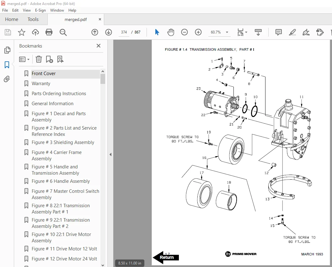
Figure # 1 4 Transmission Assembly, Part # 1 374
Figure # 1 5 Transmission Assembly, Part # 2 376
Figure # 1 6 Drive Motor Assembly 378
Figure # 2 1 Resistor Electrical Schematic 380
Figure # 2 2 Resistor Electrical Schematic Symbols 381
Figure # 2 3 Resistor Control Wiring Harness Assembly 382
Figure # 2 4 Resistor Power Component Wiring 384
Figure # 2 5 Control Panel Assembly 386
Figure # 2 6 Second Speed Contactor Assembly 388
Figure # 2 7 Forward & Rearward Contactor Assembly 390
Figure # 2 8 Power Connector Assembly 392
Figure # 2 9 Bosch Hydraulic Pump Motor Assembly 394
Figure # 2 10 12 Volt Drive Motor Assembly 396
Figure # 2 11 24 Volt Drive Motor Assembly 398
Figure # 2 12 Pump Motor Assembly 400
Figure # 2 13 Warning Light Assembly 402
Figure # 2 14 Transistor Electrical Schematic 404
Figure # 2 15 Transistor Electrical Schematic Symbols 405
Figure # 2 16 Transistor Control Wiring Harness Assembly 406
Figure # 2 17 Control Wiring Harness 408
Figure # 2 18 Control Panel Assembly 410
SN-20 Hydraulic Section 413
Figure # 3 1 SN-20 Two Stage Hydraulic Schematic 414
Figure # 3 2 SN-20 Two Stage Hydraulic Schematic Symbols 415
Figure # 3 3 SN-20 12/24 Volt Two Stage Mast Hydraulic System 416
Figure # 3 4 SN-20 12/24 Volt Reservoir and Pump Assembly 418
Figure # 3 5 SN-20 Bosch Pump and Motor Assembly 420
Figure # 3 6 SN-20 Lift Cylinder Assembly 422
Figure # 3 7 SN-20 Three Stage Hydraulic Schematic 424
Figure # 3 8 SN-20 Three Stage Hydraulic Schematic Symbols 425
Figure # 3 9 SN-20 12/24 Volt Three Stage Mast Hydraulic System 426
Figure # 3 10 SN-20 12/24 Volt Reservoir and Pump Assembly 428
Figure # 3 11 SN-20 Bosch Pump and Motor Assembly 430
Figure # 3 12 SN-20 Three Stage Freelift Cylinder Assembly 432
Figure # 3 13 SN-20 Three Stage Freelift Cylinder Assembly 434
SN-30 Hydraulic Section 437
Figure # 3 14 SN-30 Two Stage Hydraulic Schematic 438
Figure # 3 15 SN-30 Two Stage Hydraulic Schematic Symbols 439
Figure # 3 16 SN-30 12 Volt Two Stage Mast Hydraulic System 440
Figure # 3 17 SN-30 Hydraulic Pump and Valve Installation, 24 Volt 442
Figure # 3 18 SN-30 12 Volt Reservoir and Pump Assembly 444
Figure # 3 19 SN-30 Two Stage Mast Bosch Pump and Motor Assembly 446
Figure # 3 20 SN-30 Two Stage Lift Cylinder Assembly 448
Figure # 3 21 SN-30 Two Stage Hydraulic Reservoir Assembly 450
Figure # 3 22 SN-30 24 Volt Lift Pump and Motor Assembly 452
Figure # 3 23 SN-30 24 Volt Lift Pump Assembly 454
Figure # 3 24 SN-30 Three Stage Hydraulic Schematic 456
Figure # 3 25 SN-30 Three Stage Hydraulic Schematic Symbols 457
Figure # 3 26 SN-30 12 Volt Three Stage Mast Hydraulic System 458
Figure # 3 27 SN-30 24 Volt Three Stage Hydraulic System, Part # 1 460
Figure # 3 28 SN-30 24 Volt Three Stage Mast Hydraulic System, Part # 2 462
Figure # 3 29 SN-30 12 Volt Reservoir and Pump Assembly 464
Figure # 3 30 SN-30 Bosch Pump and Motor Assembly 466
Figure # 3 31 SN-30 Three Stage Freelift Cylinder Assembly 468
Figure # 3 32 SN-30 Three Stage Freelift Cylinder Assembly 470
Figure # 3 33 SN-30 24 Volt Three Stage Hydraulic Reservoir Assembly 472
Figure # 3 34 SN-30 24 Volt Lift Pump and Motor Assembly 474
Figure # 3 35 SN-30 Lift Pump Assembly 476
Figure # 3 36 SN-30 Manual Hydraulic Schematic 478
Figure # 3 37 SN-30 Manual Hydraulic Schematic Symbols 479
Figure # 3 38 SN-30 Manual Hydraulic System – Part # 1 480
Figure # 3 39 SN-30 Manual Hydraulic System – Part # 2 482
Figure # 3 40 SN-30 Manual Lift, Two Stage Lift Cylinder and Related Parts 484
Figure # 3 41 SN-30 Manual Lift, Three Stage Lift Cylinders and Related Parts 486
Figure # 3 42 SN-30 Manual Two/Three Spool Control Valve Assembly 488
Figure # 3 43 SN-30 Manual Lift Pump and Motor Assembly 490
Figure # 3 44 SN-30 Manual Lift Pump Assembly 492
Figure # 3 45 SN-30 Manual Lift Hydraulic Reservoir Assembly 494
Figure # 3 46 SN-30 Manual Lift, Two Stage Cylinder Assembly 496
Figure # 3 47 SN-30 Manual Lift Three Stage Freelift Cylinder Assembly 498
Figure # 3 48 SN-30 Manual Lift Three Stage Freelift Cylinder Assembly 500
SN-40 Hydraulic Section 503
Figure # 3 49 SN-40 Two Stage Hydraulic Schematic 504
Figure # 3 50 SN-40 Two Stage Hydraulic Schematic Symbols 505
Figure # 3 51 SN-40 Two Stage Hydraulic System – Part # 1 506
Figure # 3 52 SN-40 Two Stage Hydraulic System – Part # 2 508
Figure # 3 53 SN-40 Two Stage Lift Cylinder and Related Parts 510
Figure # 3 54 SN-40 Two/Three Spool Control Valve Assembly 512
Figure # 3 55 SN-40 Lift Pump and Motor Assembly 514
Figure # 3 56 SN-40 Lift Pump Assembly 516
Figure # 3 57 SN-40 Hydraulic Reservoir Assembly 518
Figure # 3 58 SN-40 Two Stage Lift Cylinder Assembly 520
Figure # 3 59 SN-40 Three Stage Hydraulic Schematic 522
Figure # 3 60 SN-40 Three Stage Hydraulic Schematic Symbols 523
Figure # 3 61 SN-40 Three Stage Hydraulic System – Part # 1 524
Figure # 3 62 SN-40 Three Stage Hydraulic System – Part # 2 526
Figure # 3 63 SN-40 Three Stage Lift Cylinders and Related Parts 528
Figure # 3 64 SN-40 Two/Three Spool Control Valve Assembly 530
Figure # 3 65 SN-40 Lift Pump and Motor Assembly 532
Figure # 3 66 SN-40 Lift Pump Assembly 534
Figure # 3 67 SN-40 Hydraulic Reservoir Assembly 536
Figure # 3 68 SN-40 Three Stage Staging Cylinder Assembly 538
Figure # 3 69 SN-40 Three Stage Freelift Cylinder Assembly 540
Figure # 4 1 Shielding Assembly 542
Figure # 4 2 Main Frame and Load Wheel Installation 544
Figure # 4 3 Caster Assembly 546
Figure # 4 4 Two/Three Spool Control Valve Mounting Assembly 548
Figure # 4 5 Pallet Centering Device 550
Figure # 5 1 SN-20/30 Two Stage Mast Installation 552
Figure # 5 2 SN-20/30 Two Stage Outer Column Assembly (Frame) 554
Figure # 5 3 SN-20/30 Two Stage Inner Column Assembly 556
Figure # 5 4 SN-20/30 Two Stage Mast Cylinder and Related Parts 558
Figure # 5 5 SN-20/30 Two Stage Mast Lift Frame and Load Backrest Assembly 560
Figure # 5 6 SN-20/30 Two Stage Fork Assembly 562
Figure # 5 7 SN-20/30 Three Stage Mast Installation 564
Figure # 5 8 SN-20/30 Three Stage Mast Outer Column Assembly 566
Figure # 5 9 SN-20/30 Three Stage Mast Intermediate Column Assembly 568
Figure # 5 10 SN-20/30 Three Stage Mast Inner Column Assembly 570
Figure # 5 11 SN-20/30 Three Stage Mast Freelift Cylinder and Related Parts 572
Figure # 5 12 SN-20/30 Three Stage Mast Lift Frame and Backrest Assembly 574
Figure # 5 13 SN-20/30 Three Stage Fork Assembly 576
Figure # 5 14 SN-40 Two Stage Mast Installation 578
Figure # 5 15 SN-40 Two Stage Mast Outer Column Assembly 580
Figure # 5 16 SN-40 Two Stage Mast Inner Column Assembly 582
Figure # 5 17 SN-40 Two Stage Mast Cylinder and Related Parts 584
Figure # 5 18 SN-40 Two Stage Mast Lift Frame and Load Backrest Assembly 586
Figure # 5 19 SN-40 Two Stage Fork Assembly 588
Figure # 5 20 SN-40 Three Stage Mast Installation 590
Figure # 5 21 SN-40 Three Stage Mast Outer Column Assembly 592
Figure # 5 22 SN-40 Three Stage Mast Intermediate Column Assembly 594
Figure # 5 23 SN-40 Three Stage Mast Inner Column Assembly 596
Figure # 5 24 SN-40 Three Stage Mast Freelift Cylinder Installation 598
Figure # 5 25 SN-40 Three Stage Mast Lift Frame and Load Backrest Assembly 600
Figure # 5 26 SN-40 Three Stage Fork Assembly 602
Figure # 10 1 Special Tools and Lubrications 604
Numerical Index 607
Front Cover 627
Parts Ordering Instructions 628
General Information 629
Alphabetical Index 630
Figure # 0 1 Decals and Parts Assembly 634
Figure # 1 1 Transmission and Handle Assembly 636
Figure # 1 2 Twist Grip Resistor & Transistor Control Handle Assembly 638
Figure # 1 3 Thumb Control Resistor & Transistor Control Handle Assembly 640
Figure # 1 4 Transmission Assembly, Part # I 642
Figure # 1 5 Transmission Assembly, Part # II 644
Figure # 1 6 Drive Motor Assembly 646
Figure # 2 1 Resistor Electrical Schematic 648
Figure # 2 2 Resistor Electrical Schematic Symbols 649
Figure # 2 3 Resistor Control Wiring Harness Assembly 650
Figure # 2 4 Resistor Power Component Wiring 652
Figure # 2 5 Resistor Control Panel Assembly 654
Figure # 2 6 Resistor Second Speed Contactor Assembly 656
Figure # 2 7 Resistor Forward & Rearward Contactor Assembly 658
Figure # 2 8 Power Connector Assembly 660
Figure # 2 9 Hydraulic Pump Motor Assembly 662
Figure # 2 10 Pump Motor Assembly 664
Figure # 2 11 Drive Motor Assembly, 12 Volt 666
Figure # 2 12 24 Volt Drive Motor Assembly 668
Figure # 2 13 Warning Light Assembly 670
Figure # 2 14 Transistor Electrical Schematic “E” 672
Figure # 2 15 Transistor Electrical Schematic Symbols “E” 673
Figure # 2 16 Transistor Control Wiring Harness “E” 674
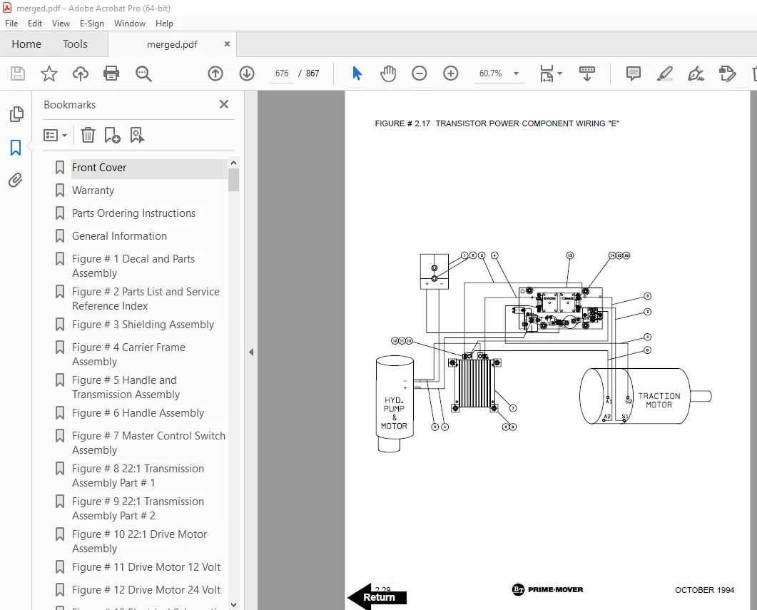
Figure # 2 17 Transistor Power Component Wiring “E” 676
Figure # 2 18 Transistor Control Panel Assembly “E” 678
Figure # 2 19 Transistor Forward & Rearward Contactor Assembly 680
Figure # 2 20 Transistor Electrical Schematic “EE” 682
Figure # 2 21 Transistor Electrical Schematic Symbols “EE” 683
Figure # 2 22 Transistor Control Wiring Harness “EE” 684
Figure # 2 23 Transistor Power Component Wiring “EE” 686
Figure # 2 24 Transistor Control Panel Assembly “EE” 688
SN-20 Hydraulic Section 691
Figure # 3 1 SN-20 Two Stage Hydraulic Schematic 692
Figure # 3 2 SN-20 Two Stage Hydraulic Schematic Symbols 693
Figure # 3 3 SN-20 Two Stage Mast Hydraulic System 694
Figure # 3 4 SN-20 Reservoir and Pump Assembly 696
Figure # 3 5 SN-20 Pump and Motor Assembly 698
Figure # 3 6 SN-20 Two Stage Lift Cylinder Assembly 700
Figure # 3 7 SN-20 Three Stage Hydraulic Schematic 702
Figure # 3 8 SN-20 Three Stage Hydraulic Schematic Symbols 703
Figure # 3 9 SN-20 Three Stage Mast Hydraulic System 704
Figure # 3 10 SN-20 Three Stage Freelift Cylinder Assembly 706
Figure # 3 11 SN-20 Three Stage Staging Cylinder Assembly 708
SN-30 Hydraulic Section 711
Figure # 3 12 SN-30 Two Stage Hydraulic Schematic 712
Figure # 3 13 SN-30 Two Stage Hydraulic Schematic Symbols 713
Figure # 3 14 SN-30 Two Stage Mast Hydraulic System, 12 Volt 714
Figure # 3 15 SN-30 Two Stage Mast Hydraulic System, 24 Volt 716
Figure # 3 16 SN-30 Reservoir and Pump Assembly 718
Figure # 3 17 SN-30 Pump and Motor Assembly 720
Figure # 3 18 SN-30 Two Stage Lift Cylinder Assembly 722
Figure # 3 19 SN-30 Two Stage Hydraulic Reservoir Assembly 724
Figure # 3 20 Lift Pump and Motor Assembly 726
Figure # 3 21 Lift Pump Assembly 728
Figure # 3 22 SN-30 Three Stage Hydraulic Schematic 730
Figure # 3 23 SN-30 Three Stage Hydraulic Schematic Symbols 731
Figure # 3 24 SN-30 Three Stage Mast Hydraulic System, 12 Volt 732
Figure # 3 25 SN-30 Three Stage Mast Hydraulic System, 24 Volt Part # I 734
Figure # 3 26 SN-30 Three Stage Mast Hydraulic System, 24 Volt Part # II 736
Figure # 3 27 SN-30 Three Stage Freelift Cylinder Assembly 738
Figure # 3 28 SN-30 Three Stage Staging Cylinder Assembly 740
Figure # 3 29 SN-30 Manual Control Hydraulic Schematic 742
Figure # 3 30 SN-30 Manual Control Hydraulic Schematic Symbols 743
Figure # 3 31 SN-30 Manual Control Hydraulic System – Part # I 744
Figure # 3 32 SN-30 Manual Control Hydraulic System – Part # II 746
Figure # 3 33 SN-30 Manual Lift, Two Stage Lift Cylinder and Related Part 748
Figure # 3 34 SN-30 Manual Lift, Three Stage Lift Cylinder and Related Part 750
Figure # 3 35 Two & Three Spool Control Valve Assembly 752
SN-40 Hydraulic Section 755
Figure # 3 36 SN-40 Two Stage Hydraulic Schematic 756
Figure # 3 37 SN-40 Two Stage Hydraulic Schematic Symbols 757
Figure # 3 38 SN-40 Manual Control Hydraulic System – Part # I 758
Figure # 3 39 SN-40 Manual Control Hydraulic System – Part # II 760
Figure # 3 40 SN-40 Manual Lift, Two Stage Lift Cylinder and Related Part 762
Figure # 3 41 SN-40 Two Stage Cylinder Assembly 764
Figure # 3 42 SN-40 Manual Control Hydraulic Schematic 766
Figure # 3 43 SN-40 Manual Control Hydraulic Schematic Symbols 767
Figure # 3 44 SN-40 Three Stage Hydraulic System – Part # I 768
Figure # 3 45 SN-40 Three Stage Hydraulic System – Part # II 770
Figure # 3 46 SN-40 Three Stage Lift Cylinder and Related Parts 772
Figure # 3 47 SN-40 Three Stage Staging Cylinder Assembly 774
Figure # 3 48 SN-40 Three Stage Freelift Cylinder Assembly 776
Figure # 4 1 Shielding Assembly 778
Figure # 4 2 Main Frame and Load Wheel Installation 780
Figure # 4 3 Spring Loaded Caster Assembly 782
Figure # 4 4 Control Valve Mounting Assembly 784
Figure # 4 5 Pallet Centering Device 786
Figure # 5 1 SN-20/30 Two Stage Mast Installation 788
Figure # 5 2 SN-20/30 Two Stage Mast Outer Column Assembly (Frame) 790
Figure # 5 3 SN-20/30 Two Stage Mast Inner Column Assembly 792
Figure # 5 4 SN-20/30 Two Stage Mast Cylinder and Related Parts 794
Figure # 5 5 SN-20/30 Two Stage Mast Lift Frame and Backrest Assembly 796
Figure # 5 6 SN-20/30 Two Stage Fork Assembly 798
Figure # 5 7 SN-20/30 Three Stage Mast Installation 800
Figure # 5 8 SN-20/30 Three Stage Mast Outer Column Assembly (Frame) 802
Figure # 5 9 SN-20/30 Three Stage Mast Intermediate Column Assembly 804
Figure # 5 10 SN-20/30 Three Stage Mast Inner Column Assembly 806
Figure # 5 11 SN-20/30 Three Stage Mast Freelift Cylinder and Related Parts 808
Figure # 5 12 SN-20/30 Three Stage Mast Lift Frame and Backrest Assembly 810
Figure # 5 13 SN-20/30 Three Stage Fork Assembly 812
Figure # 5 14 SN-40 Two Stage Mast Installation 814
Figure # 5 15 SN-40 Two Stage Mast Outer Column Assembly (Frame) 816
Figure # 5 16 SN-40 Two Stage Mast Inner Column Assembly 818
Figure # 5 17 SN-40 Two Stage Mast Cylinder and Related Parts 820
Figure # 5 18 SN-40 Two Stage Mast Lift Frame and Backrest Assembly 822
Figure # 5 19 SN-40 Two Stage Fork Assembly 824
Figure # 5 20 SN-40 Three Stage Mast Installation 826
Figure # 5 21 SN-40 Three Stage Mast Outer Column Assembly 828
Figure # 5 22 SN-40 Three Stage Mast Intermediate Column Assembly 830
Figure # 5 23 SN-40 Three Stage Mast Inner Column Assembly 832
Figure # 5 24 SN-40 Three Stage Mast Freelift Cylinder Installation 834
Figure # 5 25 SN-40 Three Stage Mast Lift Frame and Load Backrest Assembly 836
Figure # 5 26 SN-40 Three Stage Fork Assembly 838
Figure # 6 1 Hose Reel and Related Parts 839
Figure # 6 2 Dual Elbow Swivel Assembly 841
Figure # 6 3 Hose Reel Assembly 843
Figure # 10 1 Special Tools and Lubrications 845
Numerical Index 848
S.V 20/01/2025