BT Prime-Mover SR-30 Electric Walkie Reach Truck Part Manual PDF
$29.95
BT Prime-Mover SR-30 Electric Walkie Reach Truck Part Manual – PDF DOWNLOAD
Description
BT Prime-Mover SR-30 Electric Walkie Reach Truck Part Manual – PDF DOWNLOAD
FILE DETAILS:
BT Prime-Mover SR-30 Electric Walkie Reach Truck Part Manual – PDF DOWNLOAD
Language : English
Pages : 433
Downloadable : Yes
File Type : PDF
IMAGES PREVIEW OF THE MANUAL:
TABLE OF CONTENTS:
BT Prime-Mover SR-30 Electric Walkie Reach Truck Part Manual – PDF DOWNLOAD
300386-000 1991_April
300386-001 1991_July Designed and built for Long Island Railroad
300386-002 1993_August
Front Cover 2
Parts Ordering Instructions 3
General Information 4
Alphabetical Index 5
Figure # 0 1 Decals and Parts Assembly 7
Figure # 0 2 Parts List Index 9
Figure # 1 1 Transmission and Handle Assembly 13
Figure # 1 2 Standard Control Handle Assembly 15
Figure # 1 3 Thumb Control Handle Assembly 17
Figure # 1 4 Transmission Assembly, Part # 1 19
Figure # 1 5 Transmission Assembly, Part 2 21
Figure # 1 6 Drive Motor Assembly 23
Figure # 2 1 Resistor Electrical Schematic 25
Figure # 2 2 Resistor Electrical Schematic Symbols 26
Figure # 2 3 Resistor Control Wiring Harness Assembly 27
Figure # 2 4 Resistor Power Component Wiring 29
Figure # 2 5 Resistor Control Panel Assembly 31
Figure # 2 7 Forward & Rearward Contactor Assembly 33
Figure # 2 8 Power Connector Assembly 35
Figure # 2 9 Drive Motor Assembly 37
Figure # 2 10 Pump Motor Assembly 39
Figure # 2 11 Warning Light Assembly 41
Figure # 3 1 Two Stage Hydraulic Schematic 43
Figure # 3 2 Two Stage Hydraulic Schematic Symbols 44
Figure # 3 3 Two Stage Hydraulic System – Part # 1 45
Figure # 3 4 Two Stage Hydraulic System – Part # 2 47
Figure # 3 5 Two Stage Lift Cylinder and Related Parts 49
Figure # 3 6 Two & Three Spool Control Valve Assembly 51
Figure # 3 7 Two Stage Mast Lift Pump and Motor Assembly 53
Figure # 3 8 Two Stage Lift Pump Assembly 55
Figure # 3 9 Two Stage Hydraulic Reservoir Assembly 57
Figure # 3 10 Two Stage Lift Cylinder Assembly 59
Figure # 3 11 Two Stage Mast Hose Reel and Related Parts 61
Figure # 3 12 Two Stage Mast Dual Elbow Swivel Assembly 63
Figure # 3 13 Two Stage Mast Gleason Hose Reel Assembly 65
Figure # 3 14 Two Stage Reach without Tilt Hose Assembly 67
Figure # 3 15 Two Stage Mast Reach Cylinder Assembly 69
Figure # 3 16 Two Stage Reach with Tilt Hose Assembly 71
Figure # 3 17 Two Stage Mast Tilt Cylinder Assembly 73
Figure # 3 18 Three Stage Mast Hydraulic Schematic 75
Figure # 3 19 Three Stage Mast Hydraulic Schematic Symbols 76
Figure # 3 20 Three Stage Hydraulic System – Part # 1 77
Figure # 3 21 Three Stage Hydraulic System – Part # 2 79
Figure # 3 22 Three Stage Lift Cylinders and Related Parts 81
Figure # 3 23 Two & Three Spool Control Valve Assembly 83
Figure # 3 24 Three Stage Mast Lift Pump and Motor Assembly 85
Figure # 3 25 Three Stage Lift Pump Assembly 87
Figure # 3 26 Three Stage Hydraulic Reservoir Assembly 89
Figure # 3 27 Three Stage Staging Cylinder Assembly 91
Figure # 3 28 Three Stage Freelift Cylinder Assembly 93
Figure # 3 29 Three Stage Mast Hose Reel and Related Parts 95
Figure # 3 30 Three Stage Mast Dual Elbow Swivel Assembly 97
Figure # 3 31 Three Stage Mast Gleason Hose Reel Assembly 99
Figure # 3 32 Three Stage Reach without Tilt Hose Assembly 101
Figure # 3 33 Three Stage Mast Reach Cylinder Assembly 103
Figure # 3 34 Three Stage Reach with Tilt Hose Assembly 105
Figure # 3 35 Three Stage Mast Tilt Cylinder Assembly 107
Figure # 4 1 Shielding Assembly 109
Figure # 4 2 Main Frame and Load Wheel Installation 111
Figure # 4 3 Caster Assembly 113
Figure # 4 4 Two & Three Spool Control Valve Mounting Assembly 115
Figure # 5 1 Two Stage Mast Installation 117
Figure # 5 2 Two Stage Mast Outer Column Assembly 119
Figure # 5 3 Two Stage Mast Inner Column Assembly 121
Figure # 5 4 Two Stage Mast Cylinder and Related Parts 123
Figure # 5 5 Two Stage Mast Lift Frame Assembly 125
Figure # 5 6 Three Stage Reach Assembly 127
Figure # 5 7 Two Stage Mast Reach Assembly 129
Figure # 5 8 Two Stage Fork Assembly 131
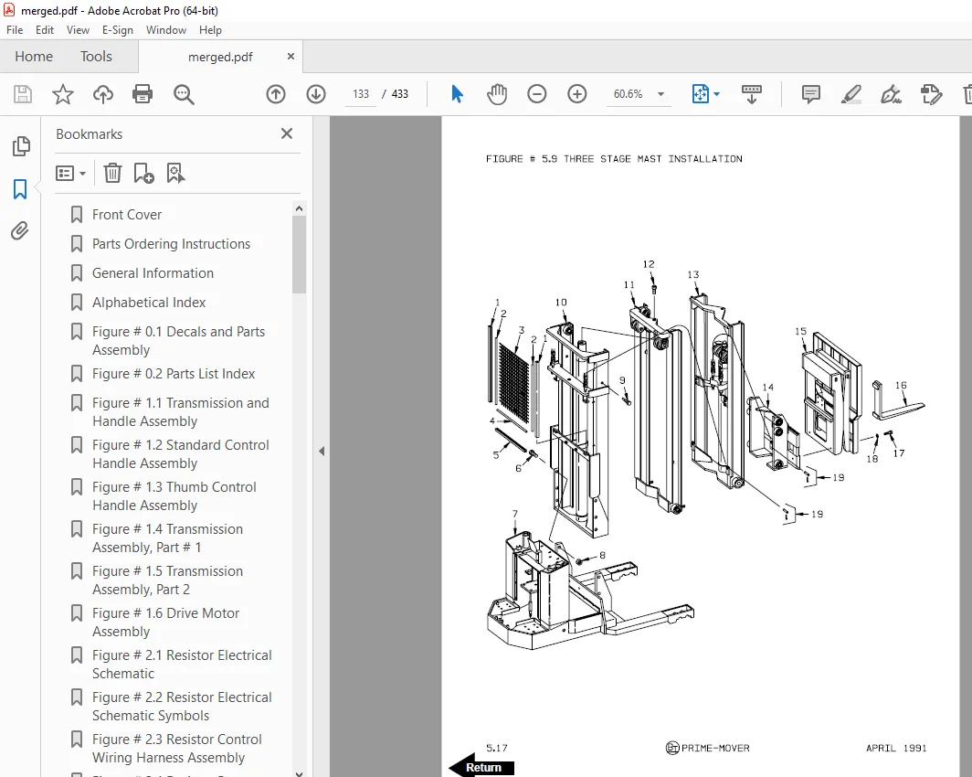
Figure # 5 9 Three Stage Mast Installation 133
Figure # 5 10 Three Stage Mast Outer Column Assembly 135
Figure # 5 11 Three Stage Mast Intermediate Column Assembly 137
Figure # 5 12 Three Stage Mast Inner Column Assembly 139
Figure # 5 13 Three Stage Mast Freelift Cylinder Installation 141
Figure # 5 14 Three Stage Mast Lift Frame Assembly 143
Figure # 5 15 Three Stage Reach Assembly 145
Figure # 5 16 Three Stage Mast Reach Assembly 147
Figure # 5 17 Three Stage Fork Assembly 149
Figure # 7 1 Special Tools and Lubrications 151
Back Cover 153
Front Cover 154
Parts Ordering Instructions 155
General Information 156
Alphabetical Index 157
Section 0 0 159
Figure # 0 1 159
Figure # 0 2 161
Section 1 0 163
Figure # 1 1 163
Figure # 1 2 165
Figure # 1 3 167
Figure # 1 4 169
Figure # 1 5 171
Section 2 0 173
Figure # 2 1 173
Figure # 2 2 174
Figure # 2 3 175
Figure # 2 4 176
Figure # 2 5 177
Figure # 2 6 179
Figure # 2 7 181
Figure # 2 8 183
Figure # 2 9 185
Figure # 2 10 187
Figure # 2 11 189
Figure # 2 12 191
Figure # 2 13 193
Section 3 0 195
Figure # 3 1 195
Figure # 3 2 196
Figure # 3 3 197
Figure # 3 4 199
Figure # 3 5 201
Figure # 3 6 203
Figure # 3 7 205
Figure # 3 8 207
Figure # 3 9 209
Figure # 3 10 211
Figure # 3 11 213
Figure # 3 12 215
Figure # 3 13 217
Figure # 3 14 219
Figure # 3 15 221
Figure # 3 16 223
Section 4 0 225
Figure # 4 1 225
Figure # 4 2 227
Figure # 4 3 229
Figure # 4 4 231
Section 5 0 233
Figure # 5 1 233
Figure # 5 2 235
Figure # 5 3 237
Figure # 5 4 239
Figure # 5 5 241
Figure # 5 6 243
Figure # 5 7 245
Figure # 5 8 247
Section 7 0 249
Figure # 7 1 249
Numerical Index 252
Back Cover 261
Front Cover 262
Parts Ordering Instructions 263
General Information 264
Alphabetical Index 265
Section 0 0 267
Figure # 0 1 Decals and Parts Assembly 267
Section 1 0 269
Figure # 1 1 Transmission and Handle Assembly 269
Figure # 1 2 Twist Grip Resistor/Transistor Control Handle Assembly 271
Figure # 1 3 Thumb Control Resistor/Transistor Control Handle Assembly 273
Figure # 1 4 Transmission Assembly, Part # 1 275
Figure # 1 5 Transmission Assembly, Part # 2 277
Figure # 1 6 Drive Motor Assembly 279
Section 2 0 281
Figure # 2 1 Resistor Electrical Schematic 281
Figure # 2 2 Resistor Electrical Schematic Symbols 282
Figure # 2 3 Resistor Control Wiring Harness Assembly 283
Figure # 2 4 Resistor Power Component Wiring 285
Figure # 2 5 Resistor Control Panel Assembly 287
Figure # 2 7 Forward & Rearward Contactor Assembly 289
Figure # 2 8 Power Connector Assembly 291
Figure # 2 9 Drive Motor Assembly 293
Figure # 2 10 Pump Motor Assembly 295
Figure # 2 11 Warning Light Assembly 297
Figure # 2 12 Transistor Electrical Schematic 299
Figure # 2 13 Transistor Electrical Schematic Symbols 300
Figure # 2 14 Transistor Control Wiring Harness Assembly 301
Figure # 2 15 Control Panel Assembly 303
Section 3 0 305
Figure # 3 1 Two Stage Hydraulic Schematic 305
Figure # 3 2 Two Stage Hydraulic Schematic Symbols 306
Figure # 3 3 Two Stage Hydraulic System – Part # 1 307
Figure # 3 4 Two Stage Hydraulic System – Part # 2 309
Figure # 3 5 Two Stage Lift Cylinder and Related Parts 311
Figure # 3 6 Two & Three Spool Control Valve Assembly 313
Figure # 3 7 Two Stage Mast Lift Pump and Motor Assembly 315
Figure # 3 8 Two Stage Lift Pump Assembly 317
Figure # 3 9 Two Stage Hydraulic Reservoir Assembly 319
Figure # 3 10 Two Stage Lift Cylinder Assembly 321
Figure # 3 11 Two Stage Mast Hose Reel and Related Parts 323
Figure # 3 12 Two Stage Mast Dual Elbow Swivel Assembly 325
Figure # 3 13 Two Stage Mast Gleason Hose Reel Assembly 327
Figure # 3 14 Two Stage Reach without Tilt Hose Assembly 329
Figure # 3 15 Two Stage Mast Reach Cylinder Assembly 331
Figure # 3 16 Two Stage Reach with Tilt Hose Assembly 333
Figure # 3 17 Two Stage Mast Tilt Cylinder Assembly 335
Figure # 3 18 Three Stage Mast Hydraulic Schematic 337
Figure # 3 19 Three Stage Mast Hydraulic Schematic Symbols 338
Figure # 3 20 Three Stage Hydraulic System – Part # 1 339
Figure # 3 21 Three Stage Hydraulic System – Part # 2 341
Figure # 3 22 Three Stage Lift Cylinders and Related Parts 343
Figure # 3 23 Two/Three Spool Control Valve Assembly 345
Figure # 3 24 Three Stage Mast Lift Pump and Motor Assembly 347
Figure # 3 25 Three Stage Lift Pump Assembly 349
Figure # 3 26 Three Stage Hydraulic Reservoir Assembly 351
Figure # 3 27 Three Stage Staging Cylinder Assembly 353
Figure # 3 28 Three Stage Freelift Cylinder Assembly 355
Figure # 3 29 Three Stage Mast Hose Reel and Related Parts 357
Figure # 3 30 Three Stage Mast Dual Elbow Swivel Assembly 359
Figure # 3 31 Three Stage Mast Gleason Hose Reel Assembly 361
Figure # 3 32 Three Stage Reach without Tilt Hose Assembly 363
Figure # 3 33 Three Stage Mast Reach Cylinder Assembly 365
Figure # 3 34 Three Stage Reach with Tilt Hose Assembly 367
Figure # 3 35 Three Stage Mast Tilt Cylinder Assembly 369
Figure # 3 36 Three Stage Mast Auxiliary Hose Assembly 371
Section 4 0 373
Figure # 4 1 Shielding Assembly 373
Figure # 4 2 Main Frame and Load Wheel Installation 375
Figure # 4 3 Caster Assembly 377
Figure # 4 4 Two & Three Spool Control Valve Mounting Assembly 379
Section 5 0 381
Figure # 5 1 Two Stage Mast Installation 381
Figure # 5 2 Two Stage Mast Outer Column Assembly 383
Figure # 5 3 Two Stage Mast Inner Column Assembly 385
Figure # 5 4 Two Stage Mast Cylinder and Related Parts 387
Figure # 5 5 Two Stage Mast Lift Frame Assembly 389
Figure # 5 6 Three Stage Reach Assembly 391
Figure # 5 7 Two Stage Mast Reach Assembly 393
Figure # 5 8 Two Stage Fork Assembly 395
Figure # 5 9 Three Stage Mast Installation 397
Figure # 5 10 Three Stage Mast Outer Column Assembly 399
Figure # 5 11 Three Stage Mast Intermediate Column Assembly 401
Figure # 5 12 Three Stage Mast Inner Column Assembly 403
Figure # 5 13 Three Stage Mast Freelift Cylinder Installation 405
Figure # 5 14 Three Stage Mast Lift Frame Assembly 407
Figure # 5 15 Three Stage Reach Assembly 409
Figure # 5 16 Three Stage Mast Reach Assembly 411
Figure # 5 17 Three Stage Fork Assembly 413
Section 10 0 415
Figure # 10 1 Special Tools and Lubrications 415
Numerical Index 418
Back Cover 433
DESCRIPTION:
BT Prime-Mover SR-30 Electric Walkie Reach Truck Part Manual – PDF DOWNLOAD
300386-000 1991_April
300386-001 1991_July Designed and built for Long Island Railroad
300386-002 1993_August
PARTS ORDERING INSTRUCTIONS:
HOW TO ORDER:
- When you order, supply the part number, quantity, model and serial numbers of your machine. Supplying this information will assure prompt, efficient handling of your order. The pictorial reference number is not needed and including it can only add confusion.
- Since your dealer carries many parts in stock and maintains up-to-date prices on all parts, he will be able to process your order immediately. If, for some reason, the part is not in stock, he will order it from the factory. In either event, he maintains a current file of service manuals, which give all available parts ordering or technical information.
- All prices are FOB factory in Muscatine, Iowa. Shipping charges are added to the price of the part shipping from the factory.
WHERE TO ORDER:
Always order parts from the dealer who sold you your BT Prime-Mover. If it is necessary for the dealer to order parts from the factory, he is able to get prompt service for you. Parts are shipped in accordance with shipping instructions given on the order.
S.V 30/01/2025