BT Prime-Mover TE-Series TE-50 TE-70 Electric Tow Tractor Parts Manual PDF
$28.95
BT Prime-Mover TE-Series TE-50 TE-70 Electric Tow Tractor Parts Manual – PDF DOWNLOAD
300446-000 1991_November
300446-001 1993_August
Manual Part Number 300446-000
Description
BT Prime-Mover TE-Series TE-50 TE-70 Electric Tow Tractor Parts Manual – PDF DOWNLOAD
FILE DETAILS:
BT Prime-Mover TE-Series TE-50 TE-70 Electric Tow Tractor Parts Manual – PDF DOWNLOAD
Language : English
Pages : 199
Downloadable : Yes
File Type : PDF
IMAGES PREVIEW OF THE MANUAL:
TABLE OF CONTENTS:
BT Prime-Mover TE-Series TE-50 TE-70 Electric Tow Tractor Parts Manual – PDF DOWNLOAD
300446-000 1991_November
300446-001 1993_August
Manual Part Number 300446-000
Front Cover 2
Parts Ordering Instructions 3
General Information 4
Alphabetical Index 5
Figure # 0 1 Decals and Parts List Assembly 7
Figure # 0 1 Parts List Index 9
Figure # 1 1 TE-50 Transmission and Handle Assembly 11
Figure # 1 2 TE-70 Transmission and Handle Assembly 13
Figure # 1 3 Handle Assembly 15
Figure # 1 4 TE-50 Transmission Assembly, Part # I 17
Figure # 1 5 TE-50 Transmission Assembly, Part # II 19
Figure # 1 6 TE-50 Drive Motor Assembly (Advanced 12 Volt 20190-01) (Prestolite 12 Volt 20190-00) 21
Figure # 1 7 TE-70 Transmission Assembly, Part # I 23
Figure # 1 8 TE-70 Transmission Assembly, Part II 25
Figure # 2 1 Resistor Master Control Switch (24121-01) 27
Figure # 2 2 Resistor 4 Speed Master Control Switch (24242-00) 29
Figure # 2 3 EV-100 SCR Master Control Switch (24455-02) 31
Figure # 2 4 TE-50 Resistor Electrical Schematic 33
Figure # 2 5 TE-50 Electrical Schematic Symbols 34
Figure # 2 6 TE-50 Two/Three Speed Control Wiring (12 Volt) 35
Figure # 2 7 TE-50 Two/Three Speed Power Component Wiring 37
Figure # 2 8 TE-50 Resistor Control Panel Assembly (12 Volt, 27259-08) 39
Figure # 2 9 TE-50 Two Speed Contactor Assembly (12 Volt, 27693-01) 41
Figure # 2 10 TE-50 Forward & Rearward Contactor Assembly (12 Volt, 27692-01) 43
Figure # 2 11 TE-50 Three Speed Contactor Panel Assembly (12 Volt, 27058-01) 45
Figure # 2 12 TE-50 Three Speed Contactor Assembly (12 Volt, 27158-00) 47
Figure # 2 13 TE-70 Resistor Electrical Schematic 49
Figure # 2 14 TE-70 Electrical Schematic Symbols 50
Figure # 2 15 TE-70 Three Speed Control Wiring (24 Volt) 51
Figure # 2 16 TE-70 Three Speed Power Wiring 53
Figure # 2 17 TE-70 Resistor Control Panel Assembly (24 Volt, 27259-09) 55
Figure # 2 18 TE-70 Two/Three Speed Contactor Assembly (24 Volt, 27693-00) 57
Figure # 2 19 TE-70 Forward & Rearward Contactor Assembly (24 Volt, 27692-00) 59
Figure # 2 20 TE-70 Three Speed Contactor Panel Assembly (24 Volt, 27266-00) 61
Figure # 2 21 TE-70 Fourth Speed Control Wiring (24 Volt) 63
Figure # 2 22 TE-70 Fourth Speed Power Component Wiring (24 Volt) 65
Figure # 2 23 TE-70 Fourth Speed Contactor Panel Assembly (27267-04) 67
Figure # 2 24 TE-70 Contactor Assembly (24 Volt, 27158-01) 69
Figure # 2 25 TE-70 EV-100 SCR Electrical Schematic 71
Figure # 2 26 TE-70 EV-100 SCR Electrical Schematic Symbols 72
Figure # 2 27 TE-70 EV-100 SCR Control Wiring 73
Figure # 2 28 TE-70 EV-100 SCR Two Speed Power Component Wiring 75
Figure # 2 29 TE-70 EV-100 SCR Contactor Panel Assembly (27707-00) 77
Figure # 2 30 TE-70 EV-100 Forward & Rearward Contactor Assembly (27692-00) 79
Figure # 2 31 TE-70 EV-100 Forward & Rearward Contactor Assembly (27693-02) 81
Figure # 2 32 TE-70 EV-100 SCR Panel Assembly 83
Figure # 2 33 TE-70 EV-100 SCR Control Panel (27691-01) 85
Figure # 2 34 Power Connector Assembly 87
Figure # 2 35 TE-50, 12 Volt Drive Motor Assembly (R90-4001, 300280-000, Advanced) 89
Figure # 2 36 TE-50, 12 Volt Drive Motor Assembly (MLD-4009, 20680-00, Prestolite) 91
Figure # 2 37 TE-70, 24 Volt Drive Motor Assembly (27895-00, 5BC48JB471) G E 93
Figure # 2 38 Wiring Assembly for Cold Storage 95
Figure # 4 1 Cushion and Floor Mat Installation 97
Figure # 4 2 Shielding Installation 99
Figure # 4 3 Frame Assembly 101
Figure # 4 4 Automatic Coupler and Tow Eye Assembly 103
Figure # 10 1 Special Tools and Lubrications 105
Numerical Index 108
Back Cover 119
Front Cover 120
Parts Ordering Instructions 121
General Information 122
Alphabetical Index 123
Figure # 0 1 Decals and Parts List Assembly 125
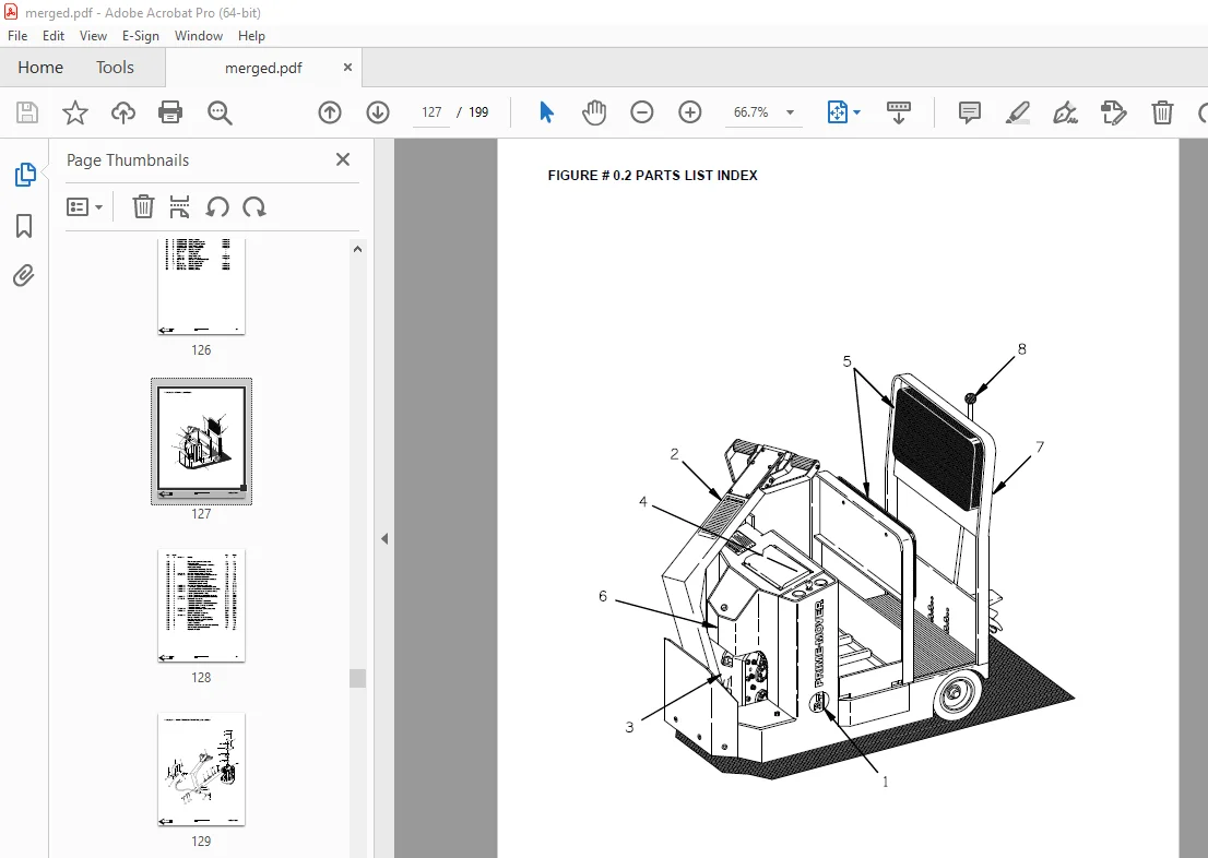
Figure # 0 2 Parts List Index 127
Figure # 1 1 Transmission and Handle Assembly 129
Figure # 1 2 Handle Assembly 131
Figure # 1 3 Transmission Assembly, Part # I 133
Figure # 1 4 Transmission Assembly, Part # II 135
Figure # 2 1 Resistor Master Control Switch (24121-01) 137
Figure # 2 2 Resistor 4 Speed Master Control Switch (24242-00) 139
Figure # 2 3 Resistor Electrical Schematic 141
Figure # 2 4 Electrical Schematic Symbols 142
Figure # 2 5 Three Speed Control Wiring 143
Figure # 2 6 Three Speed Power Wiring 145
Figure # 2 7 Resistor Control Panel Assembly (24 Volt, 27259-09) 147
Figure # 2 8 Two/Three Speed Contactor Assembly (24 Volt, 27693-00) 149
Figure # 2 9 Forward & Rearward Contactor Assembly (24 Volt, 27692-00) 151
Figure # 2 10 Three Speed Contactor Panel Assembly (24 Volt, 27266-00) 153
Figure # 2 11 Fourth Speed Control Wiring (24 Volt) 155
Figure # 2 12 Fourth Speed Power Component Wiring (24 Volt) 157
Figure # 2 13 Fourth Speed Contactor Panel Assembly (27267-04) 159
Figure # 2 14 Contactor Assembly (24 Volt, 27158-01) 161
Figure # 2 15 Transistor Electrical Schematic 163
Figure # 2 16 Transistor Electrical Schematic Symbols 164
Figure # 2 17 Transistor Control Wiring Assembly 165
Figure # 2 18 Transistor Power Wiring 167
Figure # 2 19 Transistor Contactor Panel Assembly (24594-00, 24594-01) 169
Figure # 2 20 Contactor Assembly (27693-02) 171
Figure # 2 21 Power Connector Assembly 173
Figure # 2 22 Drive Motor Assembly (28500-00) 175
Figure # 2 23 Wiring Assembly for Cold Storage 177
Figure # 4 1 Cushion and Floor Mat Installation 179
Figure # 4 2 Shielding Installation 181
Figure # 4 3 Frame Assembly 183
Figure # 4 4 Automatic Coupler and Tow Eye Assembly 185
Figure # 10 1 Special Tools and Lubrication 187
Numerical Index 190
Back Cover 199
DESCRIPTION:
BT Prime-Mover TE-Series TE-50 TE-70 Electric Tow Tractor Parts Manual – PDF DOWNLOAD
Manual Part Number 300446-000
300446-000 1991_November
300446-001 1993_August
PARTS ORDERING INSTRUCTIONS:
HOW TO ORDER:
- When you order, supply the part number, quantity, model and serial numbers of your machine. Supplying this information will assure prompt, efficient handling of your order. The pictorial reference number is not needed and including it can only add confusion.
- Since your dealer carries many parts in stock and maintains up-to-date prices on all parts, he will be able to process your order immediately. If, for some reason, the part is not in stock, he will order it from the factory. In either event, he maintains a current file of service manuals, which give all available parts ordering or technical information.
- All prices are FOB factory in Muscatine, Iowa. Shipping charges are added to the price of the part shipping from the factory.
WHERE TO ORDER:
Always order parts from the dealer who sold you your BT PRIME-MOVER. If it is necessary for the dealer to order parts from the factory, he is able to get prompt service for you. Parts are shipped in accordance with shipping instructions given on the order.
S.V 30/01/2025