BT Prime Mover TT Series TT-50 TT-70 Electric Tow Tractor Parts Manual PDF
$28.95
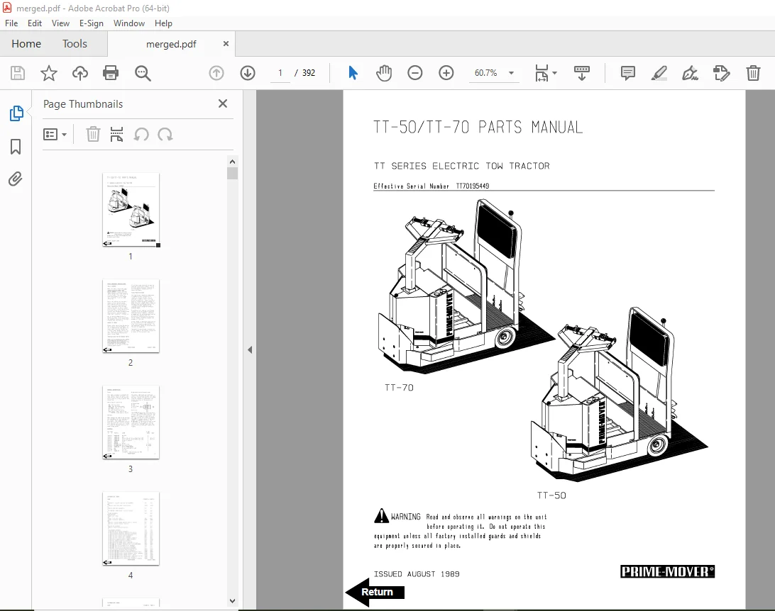
BT Prime Mover TT Series TT-50 TT-70 Electric Tow Tractor Parts Manual – PDF DOWNLOAD
Description
BT Prime Mover TT Series TT-50 TT-70 Electric Tow Tractor Parts Manual – PDF DOWNLOAD
FILE DETAILS:
BT Prime Mover TT Series TT-50 TT-70 Electric Tow Tractor Parts Manual – PDF DOWNLOAD
Language : English
Pages : 392
Downloadable : Yes
File Type : PDF
IMAGES PREVIEW OF THE MANUAL:
TABLE OF CONTENTS:
BT Prime Mover TT Series TT-50 TT-70 Electric Tow Tractor Parts Manual – PDF DOWNLOAD
Front Cover 1
Parts Ordering Instructions 2
Alphabetical Index 4
Figure # 0 1 Decals and Parts Assembly 6
Figure # 0 2 Parts List and Index 8
Figure # 1 1 TT-50 22:1 Transmission and Handle Assembly 10
Figure # 1 2 TT-70 14:1 Transmission and Handle Assembly 12
Figure # 1 3 Tee Handle Assembly 14
Figure # 1 4 TT-50 22:1 Part # I Transmission Assembly 16
Figure # 1 5 TT-50 22:1 Part # II Transmission Assembly 18
Figure # 1 6 TT-50 22:1 Drive Motor Assembly 20
Figure # 1 7 TT-70 14:1 Part # I Transmission Assembly 22
Figure # 1 8 TT-70 14:1 Part # II Transmission Assembly 24
Figure # 2 1 Resistor Master Control Switch 26
Figure # 2 2 Resistor 4 Speed Master Control Switch 28
Figure # 2 3 EV-100/EV-1 SCR Master Control Switch 30
Figure # 2 4 TT-50 Resistor Electrical Schematic 32
Figure # 2 5 Resistor Electrical Schematic Symbols 33
Figure # 2 6 TT-50 Two/Three Speed Control Wiring, 12 Volt 34
Figure # 2 7 TT-50 Two/Three Speed Power Component Wiring 36
Figure # 2 8 TT-50 Resistor Control Panel Assembly, 12 Volt 38
Figure # 2 9 TT-50 Two Speed Contactor Assembly, 12 Volt 40
Figure # 2 10 TT-50 Forward & Rearward Contactor Assembly, 12 Volt 42
Figure # 2 11 TT-50 Three Speed Contactor Panel Assembly, 12 Volt 44
Figure # 2 12 TT-50 Three Speed Contactor Assembly 46
Figure # 2 13 TT-70 Resistor Electrical Schematic 48
Figure # 2 14 Resistor Electrical Schematic Symbols 49
Figure # 2 15 TT-70 Three Speed Control Wiring, 24 Volt 50
Figure # 2 16 TT-70 Three Speed Power Component Wiring 52
Figure # 2 17 TT-70 Resistor Control Panel Assembly, 24 Volt 54
Figure # 2 18 TT-70 Two/Three Speed Contactor Assembly, 24 Volt 56
Figure # 2 19 TT-70 Forward & Rearward Contactor Assembly, 24 Volt 58
Figure # 2 20 TT-70 Three Speed Contactor Panel Assembly, 24 Volt 60
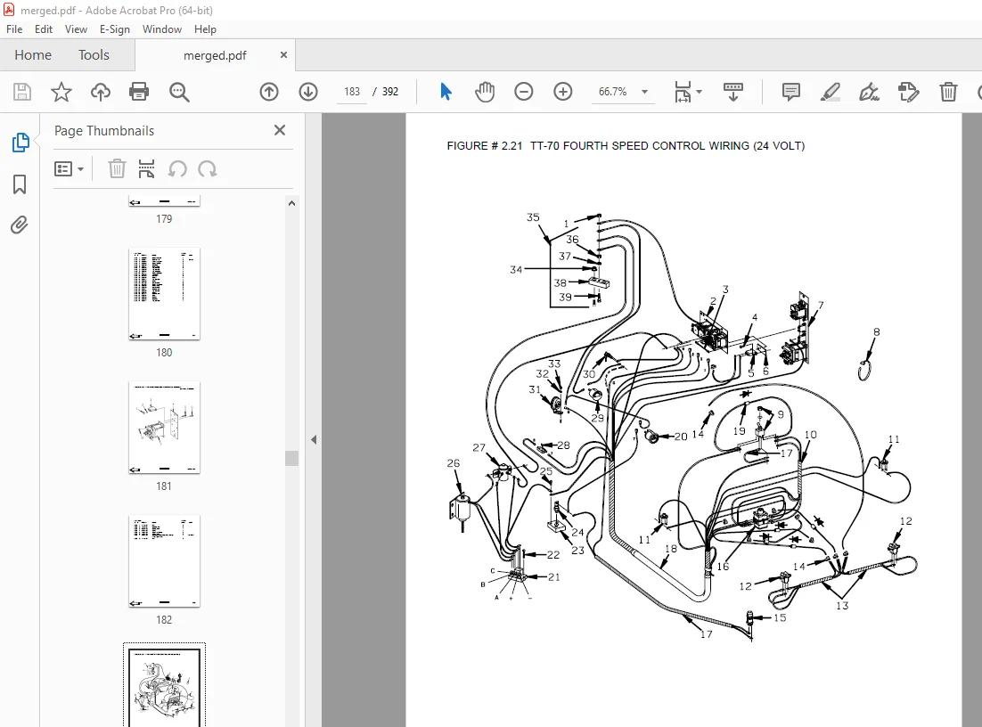
Figure # 2 21 TT-70 Fourth Speed Control Wiring, 24 Volt 62
Figure # 2 22 TT-70 Fourth Speed Power Component Wiring, 24 Volt 64
Figure # 2 23 TT-70 Fourth Speed Contactor Panel Assembly 66
Figure # 2 24 Contactor Assembly (Cableform), 24 Volt 68
Figure # 2 25 TT-70 EV-100 SCR Trucks Electrical Schematic 70
Figure # 2 26 TT-70 EV-100 SCR Truck Electrical Schematic Symbols 71
Figure # 2 27 TT-70 EV-100 SCR Two/Three Speed Control Wiring 72
Figure # 2 28 TT-70 EV-100 SCR Two Speed Power Component Wiring 74
Figure # 2 29 TT-70 EV-100 SCR Contactor Panel Assembly 76
Figure # 2 30 TT-70 EV-100 SCR Forward & Rearward Contactor Assembly 78
Figure # 2 31 TT-70 EV-100 1A Contactor Assembly 80
Figure # 2 32 TT-70 EV-100 SCR Two Speed Panel Assembly 82
Figure # 2 33 TT-70 EV-100 SCR Three Speed Power Component Wiring 84
Figure # 2 34 TT-70 EV-100 SCR Three Speed Contactor Panel Assembly 86
Figure # 2 35 TT-70 EV-100 SCR Two/Three Speed Control Panel 88
Figure # 2 36 Power Connector Assembly 90
Figure # 2 37 TT-50 22:1 Drive Motor Assembly, 12 Volt 92
Figure # 2 38 TT-70 14:1 Drive Motor Assembly 94
Figure # 2 39 Wiring Assembly for Cold Storage 96
Figure # 4 1 Cushion and Floor Mat Installation 98
Figure # 4 2 Shielding Assembly 100
Figure # 4 3 Frame Assembly 102
Figure # 4 4 Automatic Coupler and Tow Eye Assembly 104
Figure # 6 1 Special Tools and Lubrications 106
Numerical Index 109
Front Cover 122
Parts Ordering Instructions 123
General Information 124
Alphabetical Index 125
Figure # 0 1 Decals and Parts Assembly 129
Figure # 1 1 TT-50 22:1 Transmission and Handle Assembly 131
Figure # 1 2 TT-70 14:1 Transmission and Handle Assembly 133
Figure # 1 3 Tee Handle Assembly 135
Figure # 1 4 TT-50 22:1 Transmission Assembly, Part # I 137
Figure # 1 5 TT-50 22:1 Transmission Assembly, Part # II 139
Figure # 1 6 TT-50 22:1 Drive Motor Assembly 141
Figure # 1 7 TT-70 14:1 Transmission Assembly, Part # I 143
Figure # 1 8 TT-70 14:1 Transmission Assembly, Part II 145
Figure # 2 1 Resistor Master Control Switch 147
Figure # 2 2 Resistor 4 Speed Master Control Switch 149
Figure # 2 3 EV-100 SCR Master Control Switch 151
Figure # 2 4 TT-50 Resistor Electrical Schematic 153
Figure # 2 5 TT-50 Resistor Electrical Schematic Symbols 154
Figure # 2 6 TT-50 Two/Three Speed Control Wiring 155
Figure # 2 7 TT-50 Two/Three Speed Power Component Wiring 157
Figure # 2 8 TT-50 Resistor Control Panel Assembly, 12 Volt 159
Figure # 2 9 TT-50 Two Speed Contactor Assembly, 12 Volt 161
Figure # 2 10 TT-50 Forward & Rearward Contactor Assembly, 12 Volt 163
Figure # 2 11 TT-50 Three Speed Contactor Panel Assembly, 12 Volt 165
Figure # 2 12 TT-50 Three Speed Contactor Assembly, 12 Volt 167
Figure # 2 13 TT-70 Resistor Electrical Schematic 169
Figure # 2 14 TT-70 Resistor Electrical Schematic Symbols 170
Figure # 2 15 TE-70 Three Speed Control Wiring, 24 Volt 171
Figure # 2 16 TT-70 Three Speed Power Wiring 173
Figure # 2 17 TT-70 Resistor Control Panel Assembly, 24 Volt 175
Figure # 2 18 TT-70 Three Speed Contactor Assembly, 24 Volt 177
Figure # 2 19 TT-70 Forward & Rearward Contactor Assembly, 24 Volt 179
Figure # 2 20 TT-70 Three Speed Contactor Panel Assembly, 24 Volt 181
Figure # 2 21 TT-70 Fourth Speed Control Wiring, 24 Volt 183
Figure # 2 22 TT-70 Fourth Speed Power Component Wiring, 24 Volt 185
Figure # 2 23 TT-70 Fourth Speed Contactor Panel Assembly 187
Figure # 2 24 TT-70 Contactor Assembly, 24 Volt 189
Figure # 2 25 TT-70 EV-100 SCR Electrical Schematic 191
Figure # 2 26 TT-70 EV-100 SCR Electrical Schematic Symbols 192
Figure # 2 27 TT-70 EV-100 SCR Two/Three Speed Control Wiring 193
Figure # 2 28 TT-70 EV-100 SCR Two Speed Power Component Wiring 195
Figure # 2 29 TT-70 EV-100 SCR Contactor Panel Assembly 197
Figure # 2 30 TT-70 EV-100 SCR Forward & Rearward Contactor Assembly 199
Figure # 2 31 TT-70 EV-100 SCR 1A Contactor Assembly 201
Figure # 2 32 TT-70 EV-100 SCR Two Speed Panel Assembly 203
Figure # 2 33 TT-70 EV-100 SCR Three Speed Power Component Wiring 205
Figure # 2 34 TT-70 EV-100 SCR Three Speed Contactor Panel Assembly 207
Figure # 2 35 TT-70 EV-100 SCR Two/Three Speed Control Panel 209
Figure # 2 36 Resistor Power Connector Assembly 211
Figure # 2 37 TT-50 22:1 Two Speed (Only) Drive Motor Assembly, 12 Volt 213
Figure # 2 38 TT-50 22:1 Two or Three Speed Drive Motor Assembly, 12 Volt 215
Figure # 2 39 TT-70 14:1 Drive Motor Assembly, 24 Volt 217
Figure # 2 40 Wiring Assembly for Cold Storage 219
Figure # 4 1 Cushion and Floor Mat Installation 221
Figure # 4 2 Shielding Assembly 223
Figure # 4 3 Frame Assembly 225
Figure # 4 4 Automatic Coupler and Tow Eye Assembly 227
Figure # 7 1 Battery Travel Interrupt Installation 229
Figure # 10 1 Special Tools and Lubrications 231
Numerical Index 234
Front Cover 245
Parts Ordering Instructions 246
General Information 247
Alphabetical Index 248
Figure # 0 1 Decals and Parts Assembly 250
Figure # 1 1 Transmission and Handle Assembly 252
Figure # 1 2 Handle Assembly 254
Figure # 1 3 Transmission Assembly, Part # I 256
Figure # 1 4 Transmission Assembly, Part # II 258
Figure # 2 1 Resistor Master Control Switch 260
Figure # 2 2 Resistor 4 Speed Master Control Switch 262
Figure # 2 3 Resistor Electrical Schematic 264
Figure # 2 4 Resistor Electrical Schematic Symbols 265
Figure # 2 5 Three Speed Control Wiring 266
Figure # 2 6 Three Speed Power Wiring 268
Figure # 2 7 Resistor Control Panel Assembly 270
Figure # 2 8 Two/Three Speed Contactor Assembly 272
Figure # 2 9 Forward & Rearward Contactor Assembly 274
Figure # 2 10 Three Speed Contactor Panel Assembly 276
Figure # 2 11 Fourth Speed Control Wiring 278
Figure # 2 12 Fourth Speed Power Component Wiring 280
Figure # 2 13 Fourth Speed Contactor Panel Assembly 282
Figure # 2 14 Contactor Assembly 284
Figure # 2 15 Transistor Electrical Schematic 286
Figure # 2 16 Transistor Electrical Schematic Symbols 287
Figure # 2 18 Transistor Control Wiring Assembly 288
Figure # 2 19 Transistor Contactor Panel Assembly 290
Figure # 2 20 Contactor Assembly 292
Figure # 2 21 Power Connector Assembly 294
Figure # 2 22 24 Volt Drive Motor Assembly 296
Figure # 2 23 Wiring Assembly for Cold Storage 298
Figure # 4 1 Cushion and Floor Mat Installation 300
Figure # 4 2 Shielding Installation 302
Figure # 4 3 Frame Assembly 304
Figure # 4 4 Automatic Coupler and Tow Eye Assembly 306
Figure # 10 1 Special Tools and Lubrications 308
Numerical Index 311
Front Cover 318
Parts Ordering Instructions 319
General Information 320
Alphabetical Index 321
Figure # 0 1 Decals and Parts Assembly 323
Figure # 1 1 Transmission and Handle Assembly 325
Figure # 1 2 Handle Assembly 327
Figure # 1 3 Transmission Assembly, Part # I 329
Figure # 1 4 Transmission Assembly, Part II 331
Figure # 2 1 Resistor Master Control Switch 333
Figure # 2 2 Resistor 4 Speed Master Control Switch 335
Figure # 2 3 Resistor Electrical Schematic 337
Figure # 2 4 Resistor Electrical Schematic Symbols 338
Figure # 2 5 Three Speed Control Wiring 339
Figure # 2 6 Three Speed Power Wiring 341
Figure # 2 7 Resistor Control Panel Assembly 343
Figure # 2 8 Two/Three Speed Contactor Assembly 345
Figure # 2 9 Forward & Rearward Contactor Assembly 347
Figure # 2 10 Three Speed Contactor Panel Assembly 349
Figure # 2 11 Fourth Speed Control Wiring 351
Figure # 2 12 Fourth Speed Power Component Wiring 353
Figure # 2 13 Fourth Speed Contactor Panel Assembly 355
Figure # 2 14 Contactor Assembly 357
Figure # 2 15 Transistor Electrical Schematic 359
Figure # 2 16 Transistor Electrical Schematic Symbols 360
Figure # 2 17 Transistor Control Wiring Assembly 361
Figure # 2 18 Transistor Power Component Wiring 363
Figure # 2 19 Transistor Contactor Panel Assembly 365
Figure # 2 20 Contactor Assembly 367
Figure # 2 21 Power Connector Assembly 369
Figure # 2 22 Drive Motor Assembly 371
Figure # 2 23 Wiring Assembly for Cold Storage 373
Figure # 4 1 Cushion and Floor Mat Installation 375
Figure # 4 2 Shielding Installation 377
Figure # 4 3 Frame Assembly 379
Figure # 4 4 Automatic Coupler and Tow Eye Assembly 381
Figure # 10 1 Special Tools and Lubrications 383
Numerical Index 386
S.V 20/01/2025