Trusted Business
Verified & Licensed
Virus Free Files
100% Safe Downloads
Secure Payment
SSL Protected
Instant Delivery
Available Immediately
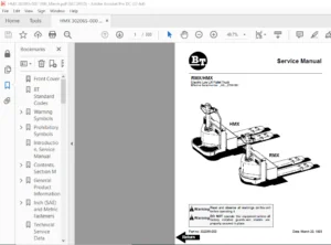
BT Prime-Mover WSX20/25 Service Manual – PDF DOWNLOAD
$27.95
BT Prime-Mover WSX20/25 Service Manual – PDF DOWNLOAD
Instant PDF Download
Available immediately
Save to Your Device
Download & keep forever
Antivirus Scanned
100% virus-free
Trusted Worldwide
175,000+ customers
Description
BT Prime-Mover WSX20/25 Service Manual – PDF DOWNLOAD
FILE DETAILS:
BT Prime-Mover WSX20/25 Service Manual – PDF DOWNLOAD
Language : English
Pages : 212
Downloadable : Yes
File Type : PDF
304944-000 1995_December
304944-000 1997_July
IMAGES PREVIEW OF THE MANUAL:
TABLE OF CONTENTS:
BT Prime-Mover WSX20/25 Service Manual – PDF DOWNLOAD
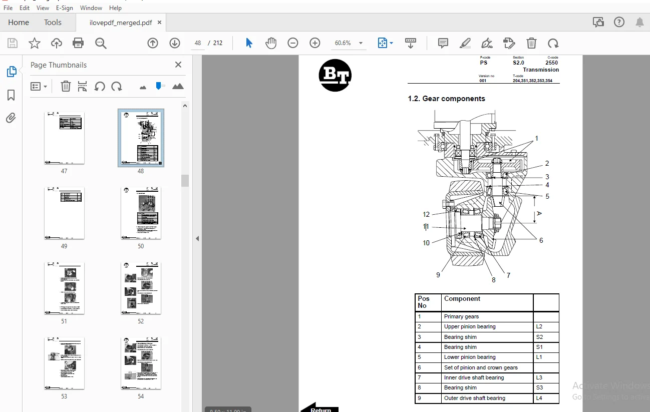
Front Cover................................................................... 2 Table of Contents............................................................. 4 Introduction.................................................................. 6 Contents, Section M........................................................... 8 General Product Information................................................... 10 1. Presentation of the Pedestrian Truck BT WSX20/25.......................... 10 1.1 Intended Application of the Truck.................................... 10 1.2 Forbidden Application of the Truck................................... 10 1.3 Truck Data........................................................... 11 1.4 Truck Dimensions..................................................... 12 1.5 Type Plate........................................................... 13 2. Main Components........................................................... 14 3. Warning and Information Signs............................................. 16 Technical Service Data........................................................ 18 Drive Motor............................................................... 18 Transmission/Gear......................................................... 18 Wheels.................................................................... 18 Hydraulic Unit............................................................ 19 Fuses..................................................................... 19 Batteries................................................................. 19 Driving Speeds............................................................ 20 Lifting/Lowering Time..................................................... 20 Current Consumption....................................................... 20 Ordering Spare Parts.......................................................... 22 Contents, Section P........................................................... 24 Introduction, Maintenance..................................................... 26 1. Safe Jacking Procedure.................................................... 26 Service Schedule.............................................................. 28 1. Preventive Maintenance Schedule....................................... 28 Lubrication Chart............................................................. 34 Oil and Grease Specification.................................................. 36 1. Approved Oils and Grease for WSX20/25................................. 36 Contents, Section S........................................................... 38 Support Arm Chassis........................................................... 40 1. General............................................................... 40 2. Main Components....................................................... 41 3. Maintenance........................................................... 41 4. Adjustment of the Support Arm Width................................... 42 5. Exchange of Support Arms.............................................. 43 Transmission.................................................................. 46 1. General Technical Description......................................... 46 1.1 Technical Data................................................... 46 1.2 Gear Components.................................................. 48 1.3 Special Tools.................................................... 50 2. Removing the Gear from the Truck...................................... 50 3. Change of Seal on the Drive Shaft..................................... 51 4. Reconditioning of the Gear............................................ 54 Electrical System............................................................. 60 1. Electrical Panel, Components.......................................... 60 2. List of Symbols....................................................... 61 2.1 Circuit Diagram 1(3)............................................. 63 2.2 Circuit Diagram 2(3)............................................. 64 2.3 Circuit Diagram 3(3)............................................. 65 3. Description of Function............................................... 66 3.1 General.......................................................... 66 3.2 Adjustable Settings.............................................. 66 3.3 References....................................................... 66 3.4 Key Switch S17 in the ON position................................ 67 3.5 The Operating Arm in Drive Position, S10, Brake Switch Closed.... 67 3.6 Driving, Fork Direction.......................................... 67 3.7 Driving, Steer Wheel Direction.................................... 68 3.8 Reversing/Motor Brake Fork Direction to Steer Wheel Direction.... 68 3.9 Reversing/Motor Brake Steer Wheel Direction to Fork Direction.... 69 3.10 Reverser Switch................................................. 69 3.11 Lifting the Forks............................................... 70 3.12 Horn............................................................ 70 4. Options............................................................... 70 4.1 Electrical Lowering of the Forks................................. 70 Battery Controller/Hourmeter.................................................. 72 1. General............................................................... 72 2. Electrical............................................................ 72 2.1 Voltage.......................................................... 72 3. Battery Controller.................................................... 73 3.1 General.......................................................... 73 3.2 Reset............................................................ 76 3.3 Keyswitch........................................................ 76 3.4 Hourmeter........................................................ 76 4. Troubleshooting....................................................... 77 4.1 Battery Discharge Indicator...................................... 77 4.2 Hourmeter........................................................ 79 Transistor Controller......................................................... 80 1. Motor Circuit......................................................... 80 2. Control Circuit....................................................... 81 3. Technical Specification............................................... 82 4. Adjustment Panel...................................................... 84 4.1 Adjustable Potentiometers........................................ 84 4.2 Connection of Handheld Terminal.................................. 84 4.3 Status LED....................................................... 85 5. Maintenance........................................................... 85 5.1 Safety........................................................... 85 5.2 Cleaning......................................................... 85 6. Diagnostics and Troubleshooting....................................... 86 PCB Card...................................................................... 88 1. The PCB............................................................... 88 2. Connectors and Adjustments............................................ 89 3. Terminals and LED's................................................... 90 Hydraulic System Version 001.................................................. 92 1. General............................................................... 92 2. Description of Function............................................... 92 2.1 Hydraulic Diagram and Components................................. 92 2.2 Main Components.................................................. 93 2.3 Description...................................................... 93 Hydraulic System Version 002.................................................. 94 1. General............................................................... 94 2. Description of Function............................................... 94 2.1 Hydraulic Diagram and Components................................. 94 2.2 Main Components.................................................. 95 2.3 Description...................................................... 95 Back Cover.................................................................... 98 Front Cover................................................................... 99 BT Standard Codes.............................................................101 Worksheet standard........................................................101 C-Code List...............................................................101 Warning Symbols...............................................................105 1. Warning Levels.........................................................105 DANGER................................................................105 WARNING...............................................................105 CAUTION...............................................................105 NOTE!.................................................................105 Prohibitory Symbols...........................................................106 NO SMOKING................................................................106 OPEN FLAMES PROHIBITED....................................................106 GENERAL PROHIBITION.......................................................106 1. Ordinance Symbols......................................................106 SAFETY SHOES..........................................................106 PROTECTIVE GLASSES....................................................106 Introduction, service manual..................................................107 Contents, Section M...........................................................109 1. Machine Information....................................................109 General product information...................................................111 Valid from machine number: 270001-........................................111 2. Presentation of the WSX20/25...........................................111 2.1. Intended application of the truck................................111 2.2. Forbidden application of the truck...............................112 2.3. Truck data.......................................................112 Truck type........................................................112 WSX20/25..........................................................112 2.4. Truck dimensions.................................................113 2.5. Truck data plate.................................................114 3. Main components........................................................115 1. Tiller arm: The truck is to be controlled by th....................115 2. Type plate: With type designation, manufacturin....................115 3. Hoods: Removable which provides good accessibil....................115 4. Instrument: (accessory) Combined hour meter/bat....................115 5. Hydraulic control: For controlling lifting and ....................115 6. Hydraulic unit: Pump motor, pump, valves, and o....................115 7. Hydraulic valves: The valves are located to pro....................115 8. Drive unit with brake: Fixed drive unit with a ....................115 9. Machine number: The manufacturing number plate ....................115 10. Electric panel: Removable, which provides good....................115 11. Battery: 24V with different Ah values. The tru....................115 12. Battery isolator/Recharging connector: The bat....................115 13. Mast: Covered by a finger protection which cov....................116 4. Warning and information signs..........................................117 1. Hydraulic control: Lifting.........................................117 2. Signal/Horn........................................................117 3. Direction: Forward/Rearward........................................117 4. General warning /informations sign.................................117 5. Hydraulic control: Lowering........................................117 6. Hydraulic oil level................................................117 7. Machine data plate.................................................117 8. No Riding decal....................................................117 9. Machine signs......................................................117 10. Do not stand on the forks/Do not walk under li....................117 11. Lifting points....................................................117 12. Pinch point.......................................................117 Inch (SAE) and Metric Fasteners...............................................119 1. Introduction...........................................................119 2. Nomenclature, Threads..................................................120 3. Strength Identification................................................121 4. Conversion of Metric and English Units.................................127 Technical service data........................................................129 Valid from machine number: 270001 -.......................................129 Ordering Spare Parts..........................................................133 1. Locate the fault on the truck..........................................133 2. Find out the machine model and serial number...........................133 3. Locate the page with the exploded diagram and f........................133 4. Locate the position number in the table. Select........................133 5. Note the part number...................................................133 6. Call the local BT dealer and state the part num........................133 Contents, Section P...........................................................135 5. Planned Maintenance....................................................135 Introduction, Maintenance.....................................................137 1. Safe Jacking Procedure.................................................137 Service schedule..............................................................139 Valid from machine number: 270001 -.......................................139 1. Preventive maintenance schedule........................................139 ITEM..................................................................139 WORK REQUIRED.........................................................139 Interval in hours.................................................139 5.................................................................139 20................................................................139 80................................................................139 250...............................................................139 500...............................................................139 1000..............................................................139 3000..............................................................139 Interval in Days/Weeks/Months.....................................139 1 d...............................................................139 1 w...............................................................139 1 m...............................................................139 3 m...............................................................139 6 m...............................................................139 12 m..............................................................139 36 m..............................................................139 Lubrication chart.............................................................145 Valid from machine number: 270001-........................................145 Pos no................................................................145 Service point.........................................................145 Interval/Running hours................................................145 Lubricant.............................................................145 500h..................................................................145 1000h.................................................................145 3000h.................................................................145 Oil and grease specification..................................................147 Valid from machine number: 270001-........................................147 2. Approved oils and grease...............................................147 Lubricant.............................................................147 Specification.........................................................147 Application area......................................................147 > - 15 C..............................................................147 < - 15 C..............................................................147 Contents, Section S...........................................................149 1. Service Instructions...................................................149 Support arm chassis...........................................................151 Valid from machine number: 270001-........................................151 2. General................................................................151 3. Main components........................................................152 Pos no................................................................152 Description...........................................................152 4. Maintenance............................................................152 5. Adjustment of the support arm width....................................153 Warning!..............................................................153 6. Exchange of support arms...............................................154 Transmission..............................................................157 Valid from machine number: 270001-....................................157 1. General technical description......................................157 1.1. Technical data...............................................158 Data..........................................................158 Description...................................................158 1.2. Gear components..............................................159 Pos No........................................................159 Component.....................................................159 1.3. Special tools................................................161 Pos No........................................................161 Tool..........................................................161 2. Removing the gear from the truck...................................161 3. Change of seal on the drive shaft..................................163 4. Reconditioning of the gear.........................................166 Electrical System.............................................................173 Valid from machine number: 270001-........................................173 1. Electrical panel, components...........................................173 2. List of symbols........................................................174 Symbol................................................................174 Description...........................................................174 Function..............................................................174 Remark................................................................174 2.1. Circuit diagram 1(3).............................................176 2.2. Circuit diagram 2(3).............................................177 2.3. Circuit diagram 3(3).............................................178 3. DESCRIPTION OF FUNCTION................................................179 3.1. General..........................................................179 3.2. Adjustable settings:.............................................179 3.3. References:......................................................179 3.4. Key switch S17 in the ON position................................180 3.5. The operating arm in drive position, S10, bra....................180 3.6. Driving, fork direction..........................................180 3.7. Driving, steer wheel direction...................................181 3.8. Reversing/motor brake fork direction to steer....................181 3.9. Reversing/motor brake steer wheel direction t....................181 3.10. Reverser switch.................................................182 3.11. Lifting the forks...............................................182 3.12. Horn............................................................183 4. Options................................................................183 4.1. Electrical lowering of the forks.................................183 5. Wire Coupler...........................................................183 5.1. Electrical wire coupler..........................................183 Battery Controller / Hourmeter / Lift Interrupt...............................185 1. General Information....................................................185 2. Electrical.............................................................185 2.1. Voltage..........................................................185 2.1.1. The Contact Voltage and Current Ratings for................186 2.1.2. Memory Retention...........................................186 3. Battery Controller (BC)................................................186 3.1. General Information..............................................186 3.1.1. Discharge Adjustment.......................................186 Battery Ah....................................................187 SETTING.......................................................187 VPC...........................................................187 SETTING.......................................................187 VPC...........................................................187 PIN NO:.......................................................187 FUNCTION......................................................187 3.2. Reset............................................................188 3.3. Key Switch.......................................................188 3.4. Hourmeter........................................................189 4. Troubleshooting........................................................189 4.1. Battery Discharge Indicator (BDI)................................189 4.1.1. No Reset...................................................189 4.1.2. Reset After Break in Power.................................189 4.1.3. No Discharge, Gauge Does Not Run Down......................190 4.1.4. No Lockout.................................................190 4.1.5. No Lift....................................................190 4.1.6. Early Lockout..............................................191 4.1.7. LEDs Do Not Light..........................................191 4.2. Hourmeter........................................................191 4.2.1. No Display.................................................191 4.2.2. Hourmeter Glass Icon Does Not Flash........................191 4.2.3. Hourmeter Glass Icon Always Flashes........................192 Transistor Controller.........................................................193 Valid from machine number: 270001-........................................193 1. Motor circuit..........................................................193 Terminal..............................................................193 Connecting............................................................193 2. Control circuit........................................................194 Pin No................................................................194 Connecting............................................................194 3. Technical specification................................................195 PARAMETER.............................................................195 RANGE.................................................................195 STD SETTING...........................................................195 UNITS.................................................................195 DESCRIPTION...........................................................195 4. Adjustment panel.......................................................196 4.1. Adjustable Potentiometers:.......................................197 4.2. Connection of hand held terminal:................................197 4.3. Status LED:......................................................197 5. Maintenance............................................................197 5.1. Safety...........................................................197 5.2. Cleaning.........................................................198 1. Remove power by disconnecting the battery......................198 2. Discharge the capacitors in the controller, by ................198 3. Remove all dirt or corrosion from the bus bar a................198 4. Make sure the connections to the bus bars are t................198 6. Diagnostics and troubleshooting........................................198 LED CODE..............................................................199 TERMINAL LCD DISPLAY..................................................199 EXPLANATION...........................................................199 POSSIBLE CAUSE........................................................199 PCB Card......................................................................201 Valid from machine number: 270001-........................................201 7. The PCB................................................................201 8. Connectors and adjustments.............................................202 Position..............................................................202 Connection/Adjustment.................................................202 9. Terminals and LED’s....................................................203 Terminal No...........................................................203 LED No................................................................203 Connection............................................................203 Function..............................................................203 Hydraulic system, mechanical lowering.........................................207 Valid from machine number: 270001-........................................207 1. General................................................................207 2. Description of function................................................207 2.1. Hydraulic diagram and components.................................207 2.2. Main components..................................................208 Pos No............................................................208 Description.......................................................208 Remark............................................................208 2.3. Description......................................................208 2.3.1. Lift.......................................................208 2.3.2. Lower......................................................208 2.3.3. Operating pressure.........................................208 1. WSX20: 2090 psi............................................208 2. WSX25: 2610 psi............................................208 2.3.4. Relief valve...............................................208 1. WSX20: 2300 psi............................................208 2. WSX25: 2870 psi............................................208 Hydraulic system, electrical lowering.........................................209 Valid from machine number: 270001-........................................209 1. General................................................................209 2. Description of function................................................209 2.1. Hydraulic diagram and components.................................209 2.2. Main components..................................................210 Pos No............................................................210 Description.......................................................210 Remark............................................................210 2.3. Description......................................................210 2.3.1. Lift.......................................................210 2.3.2. Lower......................................................210 2.3.3. Lower, electrical..........................................210 2.3.4. Operating pressure.........................................210 1. WSX20: 2090 psi............................................210 2. WSX25: 2610 psi............................................210 2.3.5. Relief valve...............................................210 1. WSX20: 2300 psi............................................210 2. WSX25: 2870 psi............................................210 Back Cover....................................................................212
S.S 06/24