BT Reach Truck OSE120, OSE120P, OSE250, OSE250P Repair Manual 7536388-040 PDF
$28.95
BT Reach Truck OSE120, OSE120P, OSE250, OSE250P Repair Manual 7536388-040 – PDF DOWNLOAD
Description
BT Reach Truck OSE120, OSE120P, OSE250, OSE250P Repair Manual 7536388-040 – PDF DOWNLOAD
FILE DETAILS:
BT Reach Truck OSE120, OSE120P, OSE250, OSE250P Repair Manual 7536388-040 – PDF DOWNLOAD
Language : English
Pages : 398
Downloadable : Yes
File Type : PDF
IMAGES PREVIEW OF THE MANUAL:
TABLE OF CONTENTS:
BT Reach Truck OSE120, OSE120P, OSE250, OSE250P Repair Manual 7536388-040 – PDF DOWNLOAD
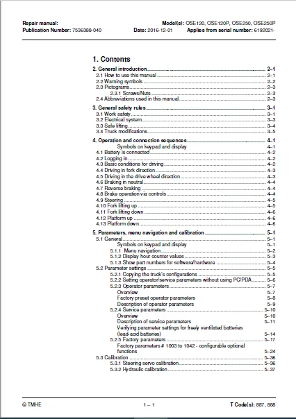
1 Contents0
2 General introduction0
21 How to use this manual0
22 Warning symbols0
23 Pictograms0
231 Screws/Nuts0
24 Abbreviations used in this manual0
3 General safety rules0
31 Work safety0
32 Electrical system0
33 Safe lifting0
34 Truck modifications0
4 Operation and connection sequences0
Symbols on keypad and display0
41 Battery is connected0
42 Logging in0
43 Basic conditions for driving0
44 Driving in fork direction0
45 Driving in the drive wheel direction0
46 Braking in neutral0
47 Reverse braking0
48 Brake operation via controls0
49 Steering0
410 Fork lifting up0
411 Fork lifting down0
412 Platform up0
413 Platform down0
5 Parameters, menu navigation and calibration0
51 General0
Symbols on keypad and display0
511 Menu navigation0
512 Display hour counter values0
513 Show part numbers for software/hardware0
52 Parameter settings0
521 Copying the truck’s configurations0
522 Setting operator/service parameters without using PC/PDA0
523 Operator parameters0
Overview0
Factory preset operator parameters0
Description of operator parameters0
524 Service parameters0
Overview0
Description of service parameters0
Verifying parameter settings for freely ventilated batteries (lead-acid batteries)0
525 Factory parameters0
Factory parameters # 1003 to 1042 – configurable optional functions0
53 Calibration0
531 Steering servo calibration0
532 Hydraulic calibration0
6 Installation and commissioning0
61 Transporting the truck0
62 Transporting the mast0
63 Safe lifting0
64 Battery installation0
641 Safety for battery handling0
642 Installing the battery0
Battery indicator0
65 Using PIN codes0
651 General0
652 Programming PIN codes0
653 PIN code defaults0
66 Setting parameters0
661 Setting collision sensor parameters (option)0
Collision sensor parameters 105 and 1060
PIN code programming for truck reset0
662 Setting battery parameters0
67 Function check0
7 Maintenance0
71 Introduction0
72 Maintenance instructions0
721 Cleaning and washing0
722 High-pressure washers0
723 Degreasing agents0
724 Cleaning the exterior0
725 Cleaning the chain0
726 Cleaning the motor compartment0
727 Electric components0
73 Checking normal truck function0
74 Safety checks0
75 First service0
76 Maintenance schedule0
761 Maintenance service every 500 operating hours/6 months0
762 Maintenance service every 1000 operating hours/12 months0
763 Maintenance service every 3000 operating hours/36 months0
8 Troubleshooting0
81 Towing a defective truck0
Tow using a tow truck and tow wagon:0
82 Auxiliary functions0
821 Emergency driving mode0
822 Error code history0
83 Error code system0
84 Error codes0
85 Built-in test function for the tiller arm0
851 Display test0
852 Speed control0
853 Controls for lifting/lowering0
854 Sensilift0
855 Keypad0
86 Built-in test function0
87 Digital input/output status0
871 Test mode “2” –0
872 Test mode “8” – Expansion unit SEU (option)0
9 Chassis – C00000
91 Details dampened floor0
92 Adjust dampened floor0
93 Platform with operator lift – C91300
931 Adjusting the side guides0
932 Adjusting the outer side guides0
933 Removing the platform with operator lift0
934 Reinstalling the platform with operator lift0
94 Automatic height adjustment – C93900
95 Signs, warnings, adhesive labels – C08500
10 Motors – C17000
101 Pump motor – C17100
1011 General0
1012 Replacing the pump motor0
102 Steering motor – C1730 (steering servo assembly)0
1021 General0
1022 Replacing the steering servo assembly0
1023 Gear replacement0
103 Drive motor – C17600
1031 General0
1032 Tightening torque – Drive motor0
1033 Component overview – Drive motor0
1034 Removing the drive motor0
1035 Fitting the drive motor0
1036 Replacing the temperature sensor0
1037 Replacing the RPM sensor0
1038 Replacing the speed sensor toothed wheel0
1039 Disassembly0
10310 Cleaning0
10311 Replacing the upper bearing0
10312 Replacing the lower bearing0
10313 Assembly0
11 Drive gear – C20000
111 General0
112 Component overview – drive gear0
113 Service and repairs with the drive gear in the truck0
1131 Checking and changing the oil0
1132 Replacing studs0
114 Repairs with transmission removed0
1141 Removing/fitting the drive gear0
1142 Replacing the drive shaft seal0
1143 Sealing the upper cover0
1144 Replacing the primary gear0
12 Brake system/Wheels C30000
121 General0
122 Parking brake – C33700
1221 Checking the parking brake air gap0
1222 Removing/fitting the parking brake0
1223 Cleaning the parking brake0
1224 Releasing the parking brake0
123 Drive wheel – C35300
1231 Component overview0
1232 Replacing the drive wheel0
124 Castor wheel – C35400
1241 Component overview – Castor wheel0
1242 Castor wheel maintenance and inspection0
Check0
1243 Adjusting castor wheel height0
Adjustment0
1244 Replacing the castor wheel0
Method for replacing the complete wheel0
Method for replacing the wheel bearing0
125 Fork wheels – C35500
1251 Removing/fitting for wheel OSE250, OSE250P (bogie)0
126 Wheel wear0
13 Steering system – C40000
131 General0
132 Component overview0
133 Steering unit – C41100
1331 Calibration0
1332 Disassembling/assembling the steering unit handle0
Disassembly0
Assembly0
1333 Disassembly/Assembly Replacing the potentiometer [R2]0
1334 Replacing the inductive brake sensor [S10]0
1335 Replacing the damper0
1336 Checking and replacing the lateral movement line (Ergo version)0
1337 Replacing buttons in the tiller arm handle0
Signal button/switch0
Lift/lower button0
Push button0
134 Reference sensor – C43500
1341 Replacing steering reference sensor [S65]0
135 Steering bearing – C43800
1351 Replacing the steering bearing0
14 Electrical system – C50000
141 Battery – C51100
1411 Replacing the battery0
Battery installation/replacement using a battery changing table0
Battery installation/replacement using a lifting device0
1412 Charging the battery0
1413 Performance limitations due to battery status0
142 Li-ion battery (Hoppecke)0
1421 Resetting/restarting the battery0
143 Inspecting the battery0
144 Contactor – C51900
1441 Replacing the contactor [Q10]0
145 ACT/ACC regulators – C54600
1451 General0
1452 Replacing the transistor regulator0
1453 Replacing the transistor regulator cooling fan0
15 Hydraulic system – C60000
151 General0
152 Hydraulic cleanliness0
1521 Cleaning0
1522 Packaging0
1523 Handling0
1524 Storage0
1525 Work procedures0
153 Component overview – Hydraulic system0
1531 Overview OSE2500
1532 Overview OSE120, OSE120P, OSE250P0
154 Operating pressure0
155 Pressure limiting valve0
156 Hose rupture valve0
157 Pressure sensor0
158 Hydraulic unit – C61000
1581 Overview0
Overview OSE2500
Description OSE250P, OSE120, OSE120P0
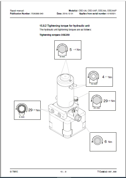
1582 Tightening torque for hydraulic unit0
Tightening torques OSE2500
Tightening torques OSE250P, OSE120, OSE120P0
1583 Emptying the hydraulic tank0
1584 Filling the tank0
159 Removing/installing the hydraulic unit0
1591 Replacing valves0
1510 Adjusting the pressure limiting valve0
15101 Adjustment OSE2500
15102 Adjustment OSE250P, OSE120, OSE120P0
1511 Hydraulic calibration0
1512 Hydraulic system, bleeding0
1513 Hydraulic couplings C62300
15131 Tightening torques for hydraulic connections0
Tapered coupling with O-ring0
Tredo seal0
Pipe coupling0
Coupling set in aluminium0
Coupling set in steel0
15132 Quick change connector0
Overview0
Assembling the quick change connector0
Dismantling the quick change connector0
1514 Main lift – C66100
15141 Component overview0
15142 Removing the lift cylinder OSE120, OSE120P0
15143 Installing the lift cylinder OSE120, OSE120P0
15144 Removing lift cylinder OSE2500
15145 Installing the lifting cylinder OSE2500
16 Mast/Lift system – C70000
161 Main lifting chain system C71200
1611 Adjustment0
1612 Checking the chain0
Noise0
Surface rust0
Rusty links0
Stiff links0
Bolt rotation0
Loose bolts0
Outline wear0
Stretching0
Damage0
Damaged plates0
Damaged bolts0
Dirty chain0
1613 Cleaning0
1614 Lubrication0
162 Fork carriage – C03800
1621 General – Fork carriage0
Checking0
Fork height OSE250/250P0
1622 Component parts OSE250, OSE250P0
1623 Component parts OSE250, OSE250P0
1624 Front linkage on older machines0
1625 Install fork carriage OSE250, OSE250P0
1626 Roller replacement0
1627 Removing the fork carriage OSE250, OSE250P0
163 Fork carriage – 74200
1631 General – Fork carriage0
Inspection0
Fork height OSE250/250P0
1632 Removing the fork carriage0
1633 Install the fork carriage in the mast0
1634 Replacing the mast rollers0
1635 Checking fork carriage lateral clearance0
17 Options – C90000
171 Spider expansion unit0
172 Component overview, TWIS (Toyota Wireless Information System)0
1721 Overview OSE1200
1722 Component list0
1723 Overview OSE120P0
1724 Component list TWIS0
1725 Overview OSE250/250P0
1726 Component list TWIS0
173 E-bar0
1731 Overview0
1732 Component list E-bar0
1733 Replacement/installation method0
1734 E-bar accessories0
18 Instructions for disposal0
181 General0
182 Marking of plastics0
1821 General marking of products and packaging0
1822 Marking according to the manufacturer’s standards0
Abbreviations0
Marking examples0
183 Pressure vessels0
1831 Gas struts0
184 Sorting categories0
19 Electrical components and electrical diagram0
191 Electric components0
1911 Electric component overview0
192 Electrical wiring diagrams0
1921 List of symbols0
1922 Wiring diagram 250P – Overview0
1923 Wiring diagram 250P0
1924 Wiring diagram 120P – Overview0
1925 Wiring diagram 120P0
1926 Wiring diagram 120 – Overview0
1927 Wiring diagram 1200
1928 Wiring diagram 250 – Overview0
1929 Wiring diagram 2500
20 Hydraulics schematics0
201 Schematics OSE120P0
202 Schematics OSE1200
203 Schematics OSE250P0
204 Schematics OSE2500
21 Tools0
211 Super Seal connectors0
212 AMP connectors0
213 AMP connectors, Multilock series 0400
214 Molex connectors0
215 CPC contacts0
216 MQS contacts0
217 Grease guns0
218 Other tools0
22 Service data and grease specifications0
221 General tightening torques0
2211 Galvanised, non-oiled screws0
2212 Untreated, oiled screws0
222 Lubrication chart0
223 Oil and grease specification0
23 Technical data0
231 Basic data0
2311 Speed limitation0
Need help? Contact: [email protected]
S.V 08/24