BT RRE140/160/180/200/250 Repair Manual 7510399-040 – PDF DOWNLOAD
$31.95
BT RRE140/160/180/200/250 Repair Manual 7510399-040 – PDF DOWNLOAD
Description
BT RRE140/160/180/200/250 Repair Manual 7510399-040 – PDF DOWNLOAD
FILE DETAILS:
BT RRE140/160/180/200/250 Repair Manual 7510399-040 – PDF DOWNLOAD
Language : English
Pages :884
Downloadable : Yes
File Type : PDF
TABLE OF CONTENTS:
BT RRE140/160/180/200/250 Repair Manual 7510399-040 – PDF DOWNLOAD
1 – Table of contents
2 – General introduction 2-1
21 How to use this manual 2-1
22 Warning symbols 2-2
23 Pictograms 2-2
3 – General safety rules 3-1
31 Work safety 3-1
32 Electrical system 3-2
33 Safe lifting 3-3
4 – Descriptions of functions 4-1
41 Chassis 0000 4-1
411 Operator’s cabin (0500) 4-1
412 Cab windows (0530) 4-3
413 Operator’s seat (0620) 4-4
414 Cab heating/ventilation (0630) 4-5
415 Operator protection (0840) 4-6
42 Motors 1000 4-9
421 General 4-9
422 Electric pump motor (1710) 4-9
423 Electric steering motor (1730) 4-10
424 Fan motor/fan (1740) 4-11
425 Electric drive motor (1760) 4-12
43 Drive gear – 2000 4-14
431 General 4-14
432 Construction 4-15
44 Brake system 3100 4-16
441 General 4-16
442 Drive motor brake (travel brake) 4-17
443 Multiple disc brake, support arm (travel brake) 4-18
444 Disc brake in support arm wheels (travel brake) 4-19
445 Disc brake on the drive motor (parking brake) 4-20
45 Steering system 4000 4-21
451 General 4-21
452 Construction 4-21
453 Sensor 4-22
46 Operation area 4-23
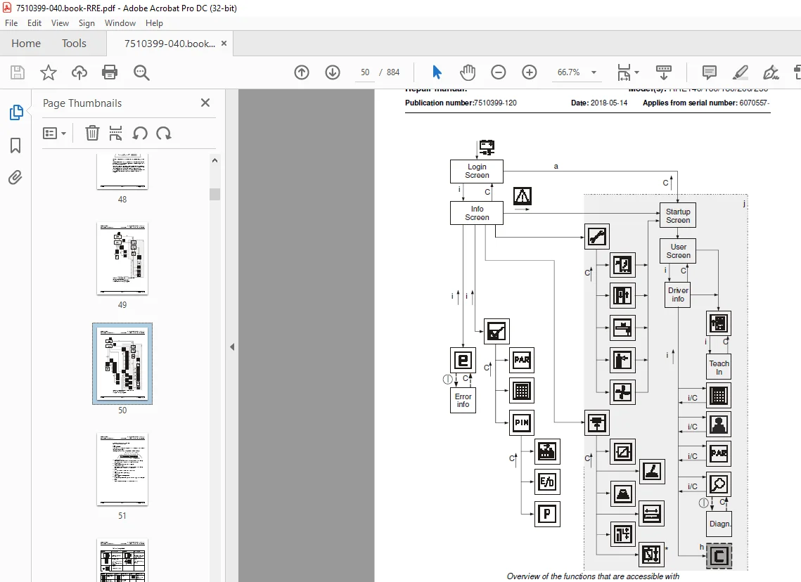
461 Truck control, overview 4-23
462 Single-function control 4-26
463 Multi-function control 4-27
464 Central Information Display – CID 4-28
465 Load Information Display – LID (option) 4-46
47 sensors and sensors (5800) 4-48
471 Inductive sensors 4-48
472 Position sensor 4-48
473 Magnetic sensor 4-49
© TMHE 1 – 2 T Code(s): 815, 816
Repair manual: Model(s): RRE140/160/180/200/250
Publication number:7510399-120 Date: 2018-05-14 Applies from serial number: 6070557-
48 Operation and connection sequences 4-50
49 Functions 4-82
491 General overview 4-82
492 MCU – main control unit 4-83
493 ACT/ACH regulators 4-84
494 Start-up 4-84
495 Shutdown 4-85
496 Driving 4-85
497 OTP 4-88
498 Steering 4-89
499 Hydraulic system 4-91
410 Height preselector, description of function 4-94
4101 Using the height preselector 4-94
4102 Symbols 4-94
4103 Travel warning 4-94
4104 Height preselector levels 4-95
4105 Level selection 4-96
4106 Height programming 4-97
4107 Height preselector and TruckCom 4-98
4108 Lift/lowering movement 4-98
4109 Parameter settings braking at height preselector 4-99
411 Hydraulic system 6000 4-100
4111 General 4-100
4112 Tank 4-100
4113 Filter 4-100
4114 Hydraulic pump 4-101
4115 Valve unit 4-101
4116 Cylinders 4-103
4117 Lift and lowering function 4-104
4118 Extra functions 4-105
4119 Cabin tilt (RRE Ergo) 4-105
412 Mast 7000 4-107
4121 Mast and reach carriage 4-107
413 Lifting devices 4-108
4131 Fork extensions 4-108
4132 Telescopic forks 4-108
414 Accessories 9000 4-110
4141 Radio equipment 4-110
4142 Extra lighting 4-110
4143 Extra warning lights/alarm 4-111
4144 Turn signal lights 4-111
4145 Movement alarm 4-112
4146 Positioning-/TV equipment 4-113
4147 Extra electrical equipment 4-115
4148 Other extra equipment 4-116
© TMHE 1 – 3 T Code(s): 815, 816
Repair manual: Model(s): RRE140/160/180/200/250
Publication number:7510399-120 Date: 2018-05-14 Applies from serial number: 6070557-
5 – Parameters 5-1
51 General 5-1
52 Displaying/changing parameters 5-1
53 Operator parameters 5-2
531 Overview 5-2
532 Connection to logged-in operator 5-3
533 Description 5-4
54 General service parameters 5-8
541 Overview 5-8
542 Description 5-8
55 Service parameters, travel functions 5-18
551 Overview 5-18
552 Description 5-18
56 Service parameters, hydraulics 5-23
561 Overview 5-23
562 Description 5-26
57 Service parameters, CID 5-48
571 Overview 5-48
572 Description 5-48
58 General factory parameters 5-56
581 Overview 5-56
582 Description 5-57
59 Factory parameters, activation of options 5-62
510 Factory parameters, calibration 5-69
6 – Installation 6-1
61 Transporting the truck 6-1
62 Transporting the mast 6-1
63 Transporting the truck 6-2
64 Commissioning 6-3
641 Tools 6-3
642 Battery 6-3
643 Mast, fitting 6-4
651 Parameters on initial operation 6-5
652 Parameters for optional equipment 6-6
7 – Maintenance 7-1
71 Introduction, maintenance 7-1
72 Safety precautions for maintenance work 7-1
73 Maintenance instructions 7-3
731 Cleaning and washing 7-3
732 High-pressure washers 7-3
733 Degreasing agents 7-4
734 Cleaning the exterior 7-4
735 Cleaning the chain 7-5
736 Cleaning the motor compartment 7-5
737 Electric components 7-5
74 Checks for cracks 7-6
741 Visual inspection 7-6
742 Crack detection 7-7
© TMHE 1 – 4 T Code(s): 815, 816
Repair manual: Model(s): RRE140/160/180/200/250
Publication number:7510399-120 Date: 2018-05-14 Applies from serial number: 6070557-
75 Periodic maintenance 7-8
751 Every 500 operating hours/180 days 7-8
752 Every 1000 operating hours/360 days 7-11
753 Every 2000 operating hours/720 days 7-18
754 Every 3000 operating hours/1080 days 7-19
755 Every 5000 operating hours/1800 days 7-21
756 Annual status inspection 7-21
76 Maintenance instructions 7-22
761 Cleaning and washing 7-22
8 – Troubleshooting 8-1
81 Abbreviations used in this section 8-1
82 Truck help functions 8-1
821 Error log menu 8-1
822 Error information menu 8-2
823 Diagnostic screens 8-2
83 Initial troubleshooting 8-16
84 Troubleshooting using blocking symbol 8-17
85 Troubleshooting using error codes 8-25
851 CID, warnings and errors 8-27
852 MCU and other warnings and errors 8-32
853 Drive system error 8-44
854 Hydraulic system error 8-58
855 Steering system, warnings and errors 8-95
856 External systems 8-104
86 Troubleshooting without indications 8-107
861 Mechanical brake (3000) 8-107
862 Steering (4000) 8-107
863 Telescopic forks 8-108
864 Log on was normal, but one or several functions
cannot be used 8-109
9 – Frame/Chassis 0000 9-1
91 General 9-1
92 Motor hood (0340) 9-1
921 Opening the motor compartment 9-1
93 Battery compartment components (0390) 9-4
931 Adjusting the battery tray 9-4
932 Adjusting the battery tray from serial number 6229952- 9-5
94 Operator’s cabin (0500) 9-6
941 Tilting the cab RRE 140 – 250 Ergo 9-6
942 Ergoled 9-7
951 Cab windows (0530) 9-10
952 Cab door (0550) 9-11
© TMHE 1 – 5 T Code(s): 815, 816
Repair manual: Model(s): RRE140/160/180/200/250
Publication number:7510399-120 Date: 2018-05-14 Applies from serial number: 6070557-
97 Operator’s compartment (0600) 9-20
971 Adjusting the seat: 9-20
972 Replacing the seat assembly 9-21
973 Replacing the seat assembly, Basic 9-23
974 Replacing the seat switch 9-25
975 Replacing the backrest 9-27
976 Replacing the chair seat 9-28
977 Replacing the seat heater switch 9-29
978 Installing the safety belt/armrest (Option) 9-30
979 Cab heating/ventilation (0630) 9-31
9710 Internal fittings (0680) 9-38
9711 Disassembly/assembly of floor plate, B version 0680 9-39
98 Operator controls (mechanical) C0640 9-41
981 Replacing pedals 9-42
99 Overhead guard/roof C0810 9-44
991 Overview 9-44
992 Removing the overhead guard 9-46
993 Fastening the overhead guard 9-50
994 Removing the roof cassette 9-55
995 Fastening the roof cassette 9-58
910 Finger/foot guards C0820 9-62
9101 Replacing a figure guard 9-62
911 Operator protection C0840 9-63
9111 Replacing the fender 9-63
912 Safety equipment (0800) 9-64
9121 Checking the overhead guard (0810) 9-64
9122 Adjusting the support lugs (0840) 9-65
10 – Motors 1000 10-1
101 Motor sensors 10-1
1011 Temperature sensor 10-1
1012 Replacing the speed sensor 10-2
102 Pump motor (1710) 10-3
1021 General 10-3
1022 Replacing the bearing on the pump motor 10-4
103 Steering motor and steering unit (1730) 10-7
1031 General 10-7
1032 Layout of the flange holes 10-7
1033 Removing the steering motor from the truck 10-8
1034 Mounting a steering motor in the truck 10-9
104 Fan motor/fan (1740) 10-10
1041 General 10-10
1042 Replacing the frequency converter cooling fan 10-10
1043 Replacing the motor compartment cooling fan 10-12
105 Drive motor (1760) 10-13
1051 General 10-13
1052 Removing the drive motor from the truck 10-14
1053 Dismantling the drive motor 10-16
1054 Cleaning 10-17
1055 Assembling the drive motor 10-18
1056 Mounting the drive motor in the truck 10-20
© TMHE 1 – 6 T Code(s): 815, 816
Repair manual: Model(s): RRE140/160/180/200/250
Publication number:7510399-120 Date: 2018-05-14 Applies from serial number: 6070557-
11 – Drive gear 2000 11-1
111 General 11-1
112 Repair- and serviceability 11-1
113 Measures 11-2
1131 Checking the oil level 11-2
1132 Oil change 11-3
1133 Leakage from the bottom cover 11-4
1134 Replacing the drive gear 11-5
1135 Overview, GK25 II (valid within
serial number range 6423715-6478769) 11-10
12 – Brake and wheel 3000 12-1
121 Travel brake system (3100) 12-1
1211 Removing the support arm’s multiple disc brake 12-1
1212 Dismantling the multiple disc brake 12-1
1213 Installing the multiple disc brake in the truck 12-4
122 Single disk brake support arm 12-5
1221 Removing the brake disc from the wheel 12-6
1222 Fitting the brake disc in the wheel 12-7
1223 Install the support arm electro-magnetic brake 12-8
1224 Removing the brake, RRE160R 12-9
1225 Removing the brake disc from the hub, RRE160R 12-10
1226 Fitting a new brake disc on the hub, RRE160R 12-11
1227 Fitting the brake in the support arm, RRE160R 12-12
1228 Checking the wheel brake’s brake force 12-13
123 Parking brake (3300) 12-14
1231 General 12-14
1232 Emergency release of the parking brake 12-14
1233 Check of braking force 12-14
1234 Remove the parking brake from the truck 12-17
1235 Fit the parking brake to the truck 12-22
124 Drive wheel (3530) 12-23
1241 General 12-23
1242 Removing the drive wheel from the truck 12-23
1243 Installing the drive wheel on the truck 12-23
125 Wheel studs (3530) 12-24
1251 Wheel stud replacement 12-24
126 Support arm wheel (3550) 12-25
1261 Removing the support arm wheel from the truck 12-25
1262 Removing the support arm wheel, RRE160R 12-26
1263 Replacing wheel bearings, RRE160R 12-27
1264 Fitting a support arm wheel to the truck, RRE160R 12-28
1265 Replacing a wheel bearing – braked wheel (A) 12-29
1266 Replacing a wheel bearing – unbraked wheel (B) 12-31
1267 Fitting a support arm wheel to the truck 12-32
1268 Support arm wheel, (280mm wheel with 1050mm
support arm width) 12-33
1269 Dismantling the wheel 12-33
12610 Fitting the support arm wheel 12-34
12611 Dismantling the wheel bearings 12-34
12612 Assembling the wheel bearings 12-34
12613 Wheel wear 12-34
© TMHE 1 – 7 T Code(s): 815, 816
Repair manual: Model(s): RRE140/160/180/200/250
Publication number:7510399-120 Date: 2018-05-14 Applies from serial number: 6070557-
13 – Steering system 4000 13-1
131 Electric steering wheel (4310) 13-1
1311 General 13-1
1312 Replacing the steering wheel 13-1
1313 Replacing the steering wheel knob 13-2
1314 Replacing the pulse transducer on the
steering wheel module 13-3
1315 Removing the steering console from the truck 13-4
1316 Replacing the wiring harness in the steering console 13-5
1317 Fit the steering console in the truck 13-7
132 Steering reference sensor (4350) 13-8
1321 Replacing the reference sensor [B17] 13-8
133 Steering bearings (4380) 13-9
1331 Steering bearing 13-10
14 – Electrical system 5000 14-1
141 Battery (5110) 14-1
1411 Battery recommendation 14-1
1412 Battery installation 14-3
1413 Replacing/installing the lithium-ion battery 14-5
1414 Installation of electrolyte mixing, fixed battery 14-8
1415 Installation of electrolyte mixing, battery replacement 14-10
142 LID (5200) 14-13
1421 Replacing the LID 14-13
1422 Replacing the LID cold store cab 14-14
143 Replacing pedals (5300) 14-15
1431 Accelerator and brake pedal 14-15
1432 Safety pedal 14-15
144 Control console (5510) 14-16
1441 General 14-16
1442 Replacement/installation of a control 14-16
1443 Replacing the multi-function control 14-17
1444 Removing the control console from the truck 14-18
1445 Replacing the access card’s circuit board 14-19
1446 Dismantling the control console 14-20
1447 Assembling the control console 14-23
1448 Placing the control console in the truck 14-24
145 Magnetic sensor (5850) 14-25
1451 Replacing the magnetic sensor [B47] 14-25
1452 Reference magnet 14-26
146 Parameter settings 14-27
1461 Configuration menu 14-27
147 PIN menu 14-30
1471 Activate PIN block menu 14-31
1472 Menu for programming a PIN (P) 14-31
© TMHE 1 – 8 T Code(s): 815, 816
Repair manual: Model(s): RRE140/160/180/200/250
Publication number:7510399-120 Date: 2018-05-14 Applies from serial number: 6070557-
148 Calibrations 14-32
1481 Calibrating the hydraulic function control 14-32
1482 Height measurement/reach movement
length calibration 14-33
1483 Valve calibration 14-38
1484 Weight calibration 14-48
149 Replacing the wiring harness 14-50
1410 main computer unit MCU (A5) 14-51
14101 Installing a new card in the truck 14-51
14102 Power supply 14-52
14103 Battery negative 14-52
14104 Internal status monitoring 14-52
14105 Resetting the battery indicator 14-52
15 – Hydraulic system 6000 15-1
151 Hydraulic hygiene 15-1
1511 Washing 15-1
1512 Packaging 15-1
1513 Handling 15-1
1514 Storage 15-2
1515 Work procedures 15-2
152 Hydraulic unit (6100) 15-3
1521 Hydraulic tank, emptying 15-4
1522 Hydraulic system, bleeding 15-5
1523 Filter 15-6
1524 Removing the pump motor from the truck 15-9
1525 Replacing the hydraulic pump or the O-Ring 15-10
1526 Fitting the pump motor in the truck 15-11
153 Main valve (6210) 15-12
1531 Emergency lowering of the forks 15-12
1532 Replacing the main valve block 15-13
1533 Replacing the lifting/lowering valves 15-15
1534 Adjusting the maximum opening pressure 15-19
154 Hydraulic connections (6230) 15-21
1541 Tightening torques for hydraulic connections 15-21
1542 Quick change connectors 15-24
155 Hydraulic system, mast (6300) 15-26
1551 Mast-mounted hose reel (6370) 15-26
1552 Fitting the hose reel 15-26
1553 Checks after fitting 15-27
© TMHE 1 – 9 T Code(s): 815, 816
Repair manual: Model(s): RRE140/160/180/200/250
Publication number:7510399-120 Date: 2018-05-14 Applies from serial number: 6070557-
156 Main lift cylinder 6610 15-28
1561 Overview 15-29
1562 Removing the air cylinder from the mast 15-31
1563 Replacing the hose rupture valve 15-32
1564 Dismantling the cylinder 15-33
1565 Dismantling the piston 15-35
1566 Dismantling the cylinder head 15-36
1567 Fitting the cylinder head seals 15-38
1568 Fitting the piston seals 15-40
1569 Assembling the cylinder 15-41
15610 Assembling a mast cylinder 15-44
157 Free lift cylinder (6620) 15-46
1571 Overview 15-47
1572 Removing the free lift cylinder from the truck 15-49
1573 Replacing the hose rupture valve, free lift cylinder 15-50
1574 Dismantling the cylinder 15-51
1575 Dismantling the piston 15-53
1576 Dismantling the cylinder head 15-54
1577 Fitting the cylinder head seals 15-55
1578 Fitting the piston seals 15-56
1579 Assembling the cylinder 15-58
15710 Assembling the free lift cylinder in the mast 15-60
158 Reach cylinder (6650) 15-61
1581 General 15-61
1582 Removing the reach cylinder from the truck 15-61
1583 Fitting the reach cylinder in the truck 15-62
159 Fork tilt cylinder (6660) 15-63
1591 General 15-63
1592 Dismantling the tilting cylinder 15-64
1593 Removing a tilt cylinder from truck number 6395129- 15-66
1594 Mounting the tilting cylinder 15-70
1595 Mounting a tilt cylinder, from truck number 6395129- 15-74
1510 Cab tilt cylinder (6660) 15-76
15101 General 15-76
15102 Overview 15-76
15103 Dismantling the cylinder 15-78
15104 Removing the piston rod 15-80
15105 Dismantling the cylinder head 15-82
15106 Fitting the cylinder head seals 15-84
15107 Mounting the piston rod 15-86
15108 Assembling the cylinder 15-88
1511 Sideshift cylinder (6670) 15-90
15111 General 15-90
15112 Overview 15-91
15113 Dismantling the cylinder from the truck 15-93
15114 Dismantling the cylinder 15-94
15115 Removing the piston rod 15-96
15116 Dismantling the cylinder head 15-98
15117 Fitting the cylinder head seals 15-100
15118 Mounting the piston rod 15-102
15119 Assembling the cylinder 15-106
151110 Refitting the cylinder in the truck 15-107
© TMHE 1 – 10 T Code(s): 815, 816
Repair manual: Model(s): RRE140/160/180/200/250
Publication number:7510399-120 Date: 2018-05-14 Applies from serial number: 6070557-
16 – Mast/Lift system 7000 16-1
161 General 16-1
162 Checking the chain 16-1
1621 Noise 16-1
1622 Surface rust 16-1
1623 Rusty links 16-1
1624 Stiff links 16-2
1625 Bolt rotation 16-2
1626 Loose bolts 16-2
1627 Outline wear 16-3
1628 Stretching 16-4
1629 Damage 16-4
16210 Damaged plates 16-5
16211 Damaged bolts 16-5
16212 Dirty chain 16-5
163 Lubricating the chain 16-5
164 Adjustment 16-6
165 Main mast 16-25 t (7100) 16-7
1651 Replacing the full mast 16-7
1652 Remove the mast from the truck 16-8
1653 Adjusting mast clearance 16-11
1654 Replacing the mast damper plates 16-17
1655 Replacing the free lift chain 16-18
1656 Assembly of frame on truck 16-21
166 Main lift chain system (7120) 16-27
1661 Main lift chain system, adjusting the fork-tofloor
distance 16-27
167 Reach carriage (7190) 16-28
1671 Adjusting the radial clearance in the reach carriage 16-29
1672 Adjusting the axial clearance in the reach carriage 16-31
168 Lifting devices (7400) 16-32
1681 Forks 16-32
1682 Forks, repairs and testing 16-34
169 Fork carriage 16-35
1691 Checking the fork carriage’s wear strip 16-35
1692 Lubricating the fork carriage 16-36
1610 Fork spread unit 16-37
16101 Servicing the fork spread unit 16-37
1611 Fork extensions with adjustable fork length 16-39
1612 Manual shuttle forks 16-41
16121 Assembly 16-41
16122 Maintenance 16-42
1613 Hydraulic shuttle forks 16-43
16131 Shuttle forks with separate flow dividers 16-44
16132 Shuttle forks with integrated flow dividers 16-46
16133 Maintenance of shuttle forks 16-48
16134 Wear 16-49
16135 Wear plate welding information 16-50
16136 Dismantling shuttle forks 16-51
16137 Shuttle fork assembly 16-52
© TMHE 1 – 11 T Code(s): 815, 816
Repair manual: Model(s): RRE140/160/180/200/250
Publication number:7510399-120 Date: 2018-05-14 Applies from serial number: 6070557-
17 – Peripherals – 8000 17-1
171 Introduction 17-1
18 – Optional equipment – 9000 18-1
181 Smart Access 2 (SA2) 18-1
1811 Replacing SA 2 18-1
182 Pre-Op Check 18-4
1821 Replacing the Pre-Op Check 18-4
19 – Appendix “Destruction instructions” 19-1
191 General 19-1
192 Marking of plastics 19-1
1921 General marking of products and packaging 19-1
1922 Marking according to Standard 19-2
193 Pressure vessels 19-3
1931 Gas struts 19-3
194 Sorting categories 19-4
20 – Wiring diagram 20-1
201 Components 20-1
202 Component location 20-12
203 Cable connections and terminal posts 20-49
2031 ACT/ACH transistor regulators 20-49
2032 Connections to CID 20-51
2033 Connections on the MCU 20-52
204 Fuse box A9 20-54
205 Overview 20-55
206 Details up to and including serial no 6206800 20-64
21 – Hydraulics schematics 21-1
211 Main valve unit 21-1
2111 RRE Std 21-1
2112 RRE Ergo 21-2
212 Hydraulic diagrams 21-3
2121 Schematics designations 21-3
2122 List of symbols 21-4
2123 Wiring diagrams RRE/RRE Ergo 21-5
22 – Tools 22-1
221 AMP connectors 22-1
222 MQS connectors 22-2
223 CPC contacts 22-4
224 Other tools 22-5
23 – Appendix “Service data and grease specifications” 23-1
231 General tightening torques 23-1
2311 Galvanised, non-oiled screws 23-1
2312 Untreated, oiled screws 23-2
232 Lubricants specification 23-3
24 – Technical data 24-1
IMAGES PREVIEW OF THE MANUAL:
S.M 5/24