BT Toyota Electric Forklift SPE125/160/135S/125L/160L Service Manual – PDF DOWNLOAD
$27.95
BT Toyota Electric Forklift SPE125/160/135S/125L/160L Service Manual – PDF DOWNLOAD
Description
BT Toyota Electric Forklift SPE125/160/135S/125L/160L Service Manual – PDF DOWNLOAD
FILE DETAILS:
BT Toyota Electric Forklift SPE125/160/135S/125L/160L Service Manual – PDF DOWNLOAD
Language : English
Pages :222
Downloadable : Yes
File Type : PDF
TABLE OF CONTENTS:
BT Toyota Electric Forklift SPE125/160/135S/125L/160L Repair Manual – PDF DOWNLOAD
1- Contents 3
2- Presentation of the truck – M2 13
21 Intended application of the truck 14
22 Forbidden application of the truck 14
23 Truck data 15
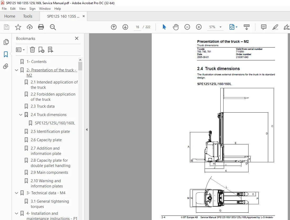
24 Truck dimensions 16
SPE125/125L/160/160L 16
25 Identification plate 18
26 Capacity plate 18
27 Addition and information plate 18
28 Capacity plate for double pallet handling 19
29 Main components 20
210 Warning and information plates 22
3- Technical data – M4 25
31 General tightening torques 30
4- Installation and maintenance instructions – P1 31
41 Truck installation 31
411 Lifting the truck 31
412 Battery installation 32
413 Putting into service 32
42 Introduction, maintenance 34
421 Safety rules during maintenance work 34
43 Cleaning and washing 36
431 External cleaning 36
432 Cleaning the motor compartment 36
433 Electric components 36
44 Safe lifting 37
5- Maintenance schedule – P2 39
51 Lubrication chart 45
6- Oil and grease specification – P3 47
7- Tools – P4 49
71 Super Seal connectors 49
72 AMP connectors 50
721 AMP Connectors, 040 series 51
73 Molex connectors 51
74 Grease guns 52
75 Other tools 53
8- Support arms – 0350 55
81 General 55
82 Main components 56
83 Maintenance 56
84 Adjusting the support arm width 57
85 Support arm replacement 58
9- Electric drive motor – 1760 59
91 Included components 59
92 Disassembly/assembly of the truck motor 61
921 Disassembly 61
922 Assembly 61
93 Service/repairs 62
931 Disassembly of the motor 62
932 Motor installation 63
933 Cleaning 63
94 Technical data 64
10- Drive unit/gear – 2550 65
101 Included components 66
1011 Technical data 67
102 Leakage from top cover 67
103 Replacing the drive axle jointing ring 67
1031 Disassembly 68
1032 Assembly 68
11- Electromagnetic brake – 3370 69
111 Main components of the brake 69
112 Maintenance 70
1121 Basic adjustment of the play 70
1122 Brake disc replacement 71
12- Electrical steering system – 4300 73
121 Electrical steering servo 73
1211 General 73
122 Steering servo components 74
123 Adjustment 75
1231 Reference sensor 75
1232 Calibration 75
Parameter 36 75
Parameter 37 75
13- Electrical systems – 5000 77
131 Electrical equipment overview 77
132 Equipment list and electrical diagram 79
1321 Electrical wiring diagram 1 of 15 83
1322 Electrical wiring diagram 2 of 15 84
1323 Electrical wiring diagram 3 of 15 85
1324 Electrical wiring diagram 4 of 15 86
1325 Electrical wiring diagram 5 of 15 87
1326 Electrical wiring diagram 6 of 15 88
1327 Electrical wiring diagram 7 of 15 89
1328 Electrical wiring diagram 8 of 15 90
1329 Electrical wiring diagram 9 of 15 91
13210 Electrical wiring diagram 10 of 15 92
13211 Electrical wiring diagram 11 of 15 93
13212 Electrical wiring diagram 12 of 15 94
13213 Electrical wiring diagram 13 of 15 95
13214 Electrical wiring diagram 14 of 15 96
13215 Electrical wiring diagram 15 of 15 97
13216 Electrical wiring diagram (SPE135S) 98
133 Functional description 99
1331 Description of steering system105
1332 Spider expansion unit (SEU)105
134 Speed limitation107
135 Hour meter and battery condition108
136 Diagnostic and troubleshooting110
1361 Fault codes110
1362 Fault code history110
1363 List of fault codes111
1364 Transistor regulator troubleshooting and error codes119
General119
Transistor regulator errors119
Resetting errors121
Safety121
1365 Built-in Test Function122
Digital inputs/outputs test mode124
1366 Display test mode127
137 Part numbers128
138 Parameters129
1381 General129
1382 Viewing parameters -CAN key not connected129
1383 Viewing parameters -CAN key connected130
1384 Setting Driver parameters131
1385 Setting Service parameters131
1386 Summary of driver parameters132
1387 Description of driver parameters133
# 2 – Maximum speed, high range133
# 3 – Maximum acceleration133
# 4 – Neutral braking effect133
# 6 – Maximum speed, low range133
# 7 – Maximum speed, “Turtle” mode133
1388 Summary of service parameters134
1389 Description of service parameters136
# 10 – PIN code136
To enter a new PIN-code:136
To remove an existing PIN-code:137
# 14 – Creep speed137
#15 – Non-configurable options137
Setting Non-configurable options137
#16 – Configurable option #1138
#17 – Configurable option #2138
#18 – Configurable option #3139
#19 – Configurable option #4139
# 20 – Hour meter selection139
# 21 – Battery size140
# 22 – Maximum fork lowering speed140
# 23 – Fork lower stop ramp140
# 25 – Service interval140
# 35 – Log off141
# 36 – Calibrate141
# 37 – Steering offset144
# 38 – Steer servo activated144
# # 39 – Log-in method & operator parameter access144
Extended keypad – General145
Extended keypad – Programming145
13810 Configurable “Option” Parameters147
General147
Parameter #16 to #19 Configurable options148
139 Technical specifications – Curtis 1243160
14- Hydraulic system – 6000161
141 Hydraulic diagram161
1411 SPE125L/160L161
1412 SPE125/160/135S162
142 Main components163
143 Description164
1431 Lifting system164
1432 The PowerTrak system164
1433 Working pressure165
1434 Overflow valve165
1435 Pressure sensor165
15- Main lift chain system – 7120167
151 General167
152 Checking the chain setting167
153 Chain inspection167
1531 Noise167
1532 Surface rust167
1533 Rusty links167
1534 Stiff links168
1535 Bolt rotation168
1536 Loose bolts168
1537 Outline wear169
1538 Stretching170
1539 Damage171
15310 Damaged discs171
15311 Damaged bolts171
15312 Dirty chain172
154 Cleaning172
155 Lubrication172
16- TruckCom175
161 General175
162 Connection175
163 Layout176
1631 Main program screen176
1632 Nodes176
1633 Icons177
1634 Tool buttons and menu bar178
1635 Information window178
1636 Status bar178
164 Connection function178
165 Disconnection function179
166 Downloading program function180
1661 Normal downloading (truck with key)180
1662 Normal downloading (truck with keypad)180
1663 Emergency downloading (truck with keypad)181
1664 Emergency downloading (truck with keypad)181
1665 Downloading in old versions of logic card181
167 Truck report function182
168 Parameters function183
169 Diagnostics function184
1691 Representation of signal colours185
1692 “Tiller arm” tab185
1693 “Drive Controller” tab (transistor regulator driving)186
1694 “Pump controller” tab (transistor regulator pump)187
1695 “EPS” (steering servo tab)188
1610 Other menu functions189
16101 Save to file189
16102 Download from file189
16103 Reset CAN adapter189
16104 Delete error code log189
16105 Reset hour meter189
16106 Read error code log189
16107 Adjust date and time189
16108 Adjusting the hour meter on older cards190
16109 Help190
About the TruckCom application190
161010 Exit190
1611 Specifications190
1612 Installation190
16121 Installation on a PC with Windows® 95/ 98191
16122 Installation on a PC with Windows XP/ 2000192
Changes in Windows® Control Panel194
16123 Installation on a PC with Windows NT197
16124 In case of communication problems with CAN197
16125 To uninstall197
17- Destruction instructions – M6199
171 General199
172 Procedure199
173 Abbreviations200
174 Sorting200
175 Chassis (0300)201
1751 Dismantling201
1752 Material handling201
176 Hoods, covers (0340)202
1761 Dismantling202
1762 Material handling202
177 Fork structure (low-lifter) (0380)203
1771 Dismantling203
1772 Material handling203
178 Travel platform including mount (0560)204
1781 Dismantling204
1782 Material handling204
179 Overhead guard (option) (0810)205
1791 Dismantling205
1792 Material handling205
1710 Operator protective device (0840)206
17101 Dismantling206
17102 Material handling206
1711 Electric pump motor (1710)207
17111 Dismantling207
17112 Material handling207
1712 Electric travel drive motor (1760)208
17121 Dismantling208
17122 Material handling208
1713 Drive unit/gear (2550)209
17131 Dismantling209
17132 Material handling209
1714 Wheels (3500)210
17141 Dismantling210
17142 Material handling210
1715 Steering arm (4110)211
17151 Dismantling211
17152 Material handling211
1716 Steering arm (4110)212
17161 Dismantling212
17162 Material handling212
1717 General electric equipment (5100)213
17171 Dismantling213
17172 Material handling213
1718 Cabling (5590)214
17181 Dismantling214
17182 Material handling214
1719 Steering and protective electronics (5700)215
17191 Dismantling215
17192 Material handling215
1720 Lift/lowering sensor (5820) and safety sensor (5830)216
17201 Dismantling216
17202 Material handling216
1721 Hydraulic unit (6100)217
17211 Dismantling217
17212 Material handling217
1722 Main mast (7100)218
17221 Dismantling218
17222 Material handling218
1723 Chassis-mounted hydraulic oil lines (6230) (and main lift cylinder (6610) )219
17231 Dismantling219
17232 Material handling219
1724 Battery charger connector (9380)220
17241 Dismantling220
17242 Material handling220
IMAGES PREVIEW OF THE MANUAL:
S.M 5/24