The 30MB3 miner is a radio-controlled drum-type continuous miner with appropriate weight balance, cutting and loading power to enable the productive mining of coal and other soft mineral in seams ranging from 1,900mm up to 4, 000mm thick.
The machine is mounted on crawler tracks that provide full mobility and sharp turning radius in both board and pillar and long wall development mining plans.
The ranging cutting head mines material from the solid face using a chainless rotating drum, and a CLA-type gathering head with high speed conveyor efficiently moves mined material to a haulage system behind the miner.
The machine’s weight and balance is designed to mine most efficiently by either sumping into the face at the top or bottom of the seam, and ripping material to the bottom or top of the seam.
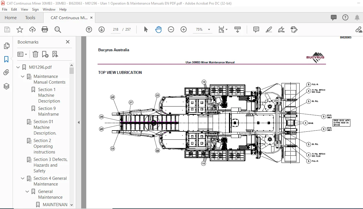
The above figure shows a general arrangement of major mechanical components. A full description of the various major sub-systems of the 30MB3 follows.
M01296.pdf............................................................................  0
	Maintenance Manual Contents.......................................................  2
		Section 1 Machine Description.................................................  2
		Section 9 Mainframe...........................................................  2
	Section 01 Machine Description....................................................  3
	Section 2 Operating instructions.................................................. 23
	Section 3 Defects, Hazards and Safety............................................. 25
	Section 4 General Maintenance..................................................... 66
		General Maintenance........................................................... 68
			MAINTENANCE AND THE CONTINUOUS MINER...................................... 68
			TORQUES................................................................... 69
			DUO-CONE SEALS............................................................ 70
			MAINTENANCE GUIDELINES.................................................... 72
			BEARING AND GEARS......................................................... 74
				1. Bearing General ................................................... 74
				2. Bearing Assembly Methods .......................................... 74
				3. Assembly Methods .................................................. 74
				4. Heating Bearings .................................................. 74
				5. Freezing/Shrinking Bearing Cups ................................... 74
				6. Tapered Roller Bearing Adjustment ................................. 74
				7. Bevel Gear Adjustment ............................................. 74
				Bearings General...................................................... 74
					Cleanliness....................................................... 74
					Keep Clean – Keep Dry............................................. 74
				Bearing Assembly Methods.............................................. 74
				Assembly Methods...................................................... 74
					Micronized Graphite for Bearing Assembly.......................... 75
					Drivers for Bearing Cups and Cones................................ 75
				Heating Bearings...................................................... 75
					Heating in Oil.................................................... 75
					Induction Heating................................................. 75
				Freezing/Shrinking Bearing Cups....................................... 76
				Tapered rolling Bearing Adjustment.................................... 76
					Thermal Expansion................................................. 76
					Torque for Zero End Play.......................................... 76
				Bevel Gear Adjustment................................................. 77
			LOCKWIRING FASTENERS...................................................... 79
				Single Wire........................................................... 79
				Wired in Pairs........................................................ 79
			SPECIAL FASTENERS......................................................... 79
			SELF-LOCKING SCREWS....................................................... 79
				Installation Recommendations.......................................... 79
			LOCKNUTS.................................................................. 80
				Installation Recommendations.......................................... 80
			COMPONENT SUBSTITUTION.................................................... 81
			SAFETY IN MAINTENANCE..................................................... 81
	Section 5 Cutting Head Assy....................................................... 82
		GENERAL DESCRIPTION........................................................... 84
		REMOVAL OF PULL IN ASSEMBLY COMPLETE.......................................... 86
		REMOVAL OF CUTTING DRUMS...................................................... 87
			Pull in Drum Assembly..................................................... 88
			Drive Drum Removal........................................................ 89
			Drive Drum Assembly....................................................... 91
		Intermediate Drum Removal..................................................... 92
			Intermediate Drum Removal LH.............................................. 95
			Intermediate Drum Assembly Right Hand and Left Hand....................... 98
			Install complete in pull Assembly......................................... 99
			Centre Drum Removal.......................................................101
			Centre Drum Assembly......................................................103
			Clutch Assembly...........................................................106
			Removal of the Cutting Head Gear Case Complete With Pull in Assemblies....107
			Reinstall Cutter Head Gear case Complete with Pull in Assemblies..........111
			Removal of Cutter Head Motor (LH and RH)..................................112
			Installation of Cutter head Motor.........................................113
			Removal of the Cutting Head Input Gearcase................................115
			Installation of Cutter Head Input Gear case...............................116
		REMOVAL OF THE CUTTING HEAD SUPPORT FROM THE MAINFRAME........................117
		INSTALLATION OF CUTTING HEAD ASSEMBLY TO THE MAIN FRAME.......................120
	Section 6 Gathering Head Assy.....................................................122
		GENERAL DESCRIPTION ..........................................................125
		REMOVAL AND REPLACING GATHERING HEAD SHEAR SHAFT..............................126
		CONVEYOR CHAIN DISASSEMBLY....................................................128
		REMOVAL OF FOOT SHAFT AND CLA's...............................................130
			Removing the CLA’s........................................................131
			Refitting the CLA’s.......................................................132
		REMOVAL OF DRIVE MOTOR INPUT GEAR CASE AND C.L.A POT .........................133
		REASSEMBLY OF GATHERING HEAD GEARCASES........................................137
		REMOVAL OF THE GATHERING HEAD FROM THE MAIN FRAME.............................138
		INSTALLATION OF THE GATHERING HEAD............................................142
	Section 7 Conveyor Assy...........................................................145
		GENERAL DESCRIPTION...........................................................147
		CONVEYOR CHAIN REMOVAL........................................................148
		CONVEYOR CHAIN INSTALLATION...................................................150
		REMOVAL OF THE CONVEYOR ASSEMBLY FROM THE MINER...............................152
		INSTALLATION OF THE CONVEYOR ASSEMBLY.........................................155
		REMOVAL OF DISCHARGE CONVEYOR.................................................156
		REMOVAL OF TAIL ROLLER .......................................................160
	Section 8 Traction System.........................................................162
		GENERAL DESCRIPTION...........................................................164
		REMOVAL OF THE TRAM DRIVE GEAR CASE ASSEMBLYCOMPLETE WITH DRIVE MOTOR.........165
		INSTALLATION OF THE TRAM DRIVE GEAR CASE ASSEMBLY.............................169
		INSTALLATION OF A TRAM MOTOR..................................................173
		CRAWLER CHAIN REMOVAL.........................................................174
		CRAWLER CHAIN INSTALLATION....................................................177
		CRAWLER TAKE-UP ROLLER REMOVAL................................................180
		CRAWLER TAKE-UP ROLLER INSTALLATION ..........................................181
	Section 9 Mainframe...............................................................182
		STABLISING SHOE ASSEMBLY......................................................184
			Stabiliser Cylinder Removal ..............................................184
			Cylinder Installation.....................................................186
		STABILISER SHOE REMOVAL.......................................................187
		SHOE INSTALLATION.............................................................188
	Section 10 Cylinder Servicing.....................................................189
		CYLINDER REMOVAL AND INSTALLATION.............................................191
		CUTTERHEAD RAISE AND LOWER CYLINDER...........................................192
			Cutter Head Raise/Lower Cylinder Removal..................................193
			Cutter Head Raise/Lower Cylinder Installation.............................194
		GATHERING HEAD RAISE AND LOWER CYLINDER.......................................195
			Gathering Head Raise/Lower Cylinder Removal...............................196
			Gathering Head Raise/Lower Cylinder Installation..........................197
		CONVEYOR RAISE AND LOWER CYLINDER ............................................198
			Conveyor Raise/Lower Cylinder Removal.....................................199
			Conveyor Raise/Lower Cylinder Installation................................200
		CONVEYOR SWING CYLINDER.......................................................201
			Conveyor Swing Cylinder Removal...........................................202
			Conveyor Swing Cylinder Installation......................................203
		PLOW CYLINDERS................................................................204
			Plow Cylinder Removal.....................................................205
			Plow Cylinder Installation................................................205
		CONVEYOR TAKE-UP CYLINDERS....................................................206
			Conveyor Take-up Cylinder Removal.........................................207
			Conveyor Take-up Cylinder Installation....................................208
		HYDRAULIC PUMP INSTALLATION...................................................211
		REMOVAL AND REPLACEMENT OF PUMP DRIVE MOTOR...................................213
			Pump Drive Motor Removal..................................................214
			Pump Drive Motor Installation.............................................214
	Section 11 Operator Servicing And Maintenance.....................................215
		OPERATOR / TRADESMAN SERVICING AND MAINTENANCE................................217
		TOP VIEW LUBRICATION..........................................................218
		LEFT HAND SIDE LUBRICATION....................................................219
		LUBRICATION CHART.............................................................221
		LUBRICATION – GEAR OIL........................................................222
			Tram Gear cases...........................................................222
			Cutter Head Gear Cases....................................................223
			Cutter Head Input Gear Cases..............................................224
			Gathering Head (POT) Gear Cases...........................................225
			Gathering Head Input Gear Cases...........................................226
			Traction Idler Roller.....................................................227
		GREASING......................................................................228
		TRAM BRAKES...................................................................228
		FILTERS.......................................................................228
			Right Hand Filters........................................................228
		CHAIN ADJUSTMENTS.............................................................229
			Crawler Track Chain Adjustment............................................229
		MAINTENANCE MODE..............................................................231
			Check and Fill Hydraulic Oil Reservoir....................................231
			Hydraulic Oil Power Fill..................................................232
			Gear Case Oil Power Fill..................................................233
		REPAIR OR REPLACE WATERSPRAYS.................................................234
		MACHINE CUTTING PICKS.........................................................235
	Section 12  Hydraulic components assembly.........................................236
		DESCRIPTION...................................................................238
		MECHANICAL....................................................................239
		HYDRAULICS....................................................................240
		HYDRAULIC PUMP................................................................241
			Power Cut Off Control – D.................................................242
			Load Sensing Control – S..................................................242
		PUMP ADJUSTMENT...............................................................243
			Power Controller – LR.....................................................244
		VALVE BANK INFORMATION........................................................246
		ADJUSTMENTS...................................................................247
			Conveyor Tension and Tramming Brake Coolant...............................247
	Section 13  Water General.........................................................248
		Water Reticulation............................................................250
			GENERAL...................................................................250
				Circuit 1 (Right Side)................................................250
				Circuit 2 (Left Side).................................................250
				Tramming..............................................................251
				Water Sprays..........................................................252
	Section 14 Maintenance Matrix.....................................................254