Canon MF4300 D450d Service Manual Repair Troubleshooting Guide PDF
Original price was: $95.00.$18.95Current price is: $18.95.
Complete Canon factory service manual for MF4300 series multifunction printers including D450d, MF4310, MF4320d, MF4330d, MF4340d, MF4350d, MF4370dn, and MF4380dn. Professional technical documentation with 182 pages covering disassembly, troubleshooting, error codes, service mode procedures, and parts replacement. Includes detailed diagrams, adjustment procedures, maintenance schedules, and electrical schematics. Essential for Canon technicians and printer repair specialists. Instant PDF download.
Description
Canon MF4300 D450d Service Manual Repair Troubleshooting Guide PDF DOWNLOAD
DESCRIPTION
Official Canon MF4300 Series Service & Repair Manual
This comprehensive Canon MF4300 series service manual provides complete factory-level technical documentation for professional printer technicians and service engineers maintaining Canon i-SENSYS multifunction laser printers. Essential for authorized Canon service centers, independent printer repair shops, and corporate IT departments servicing Canon MFP equipment.
COMPLETE MANUAL STRUCTURE
CHAPTER 1: INTRODUCTION
Product Specifications:
Names of Parts:
- External view with component identification
- Section view (host machine) – internal layout
- Section view (ADF/DADF) – document feeder internals
- Control panel layout and buttons
Safety Information:
- Safety of the host machine’s laser mechanism
- CDRH regulations compliance
- Handling of the laser assembly (CLASS 1 laser product)
- Safety of the toner (handling precautions)
- Fire attention warnings
- Lithium battery replacement/disposal procedures
Product Specifications:
- Host machine specifications:
- Print technology
- Print speed
- Resolution
- Memory capacity
- Paper handling
- Duty cycle
- ADF/DADF specifications:
- Document feeder capacity
- Scanning speed
- Paper size support
- FAX specifications:
- Modem speed
- Memory capacity
- Transmission speed
Function List:
- Scanning range (ADF/DADF) – supported paper sizes
- Scanning range (copyboard) – flatbed specifications
- Recording range (Copy) – copy area specifications
- Recording range (Reception) – fax receive area
- Recording range (Printer) – printable area
- Operation environment of the printer driver
- Network specifications – USB, Ethernet, wireless
CHAPTER 2: BASIC OPERATION
Construction:
- Function configuration overview
- System architecture
- Component relationships
Basic Sequence:
- Basic operation sequence diagrams
- Power-on initialization
- Job processing flow
- Timing charts
CHAPTER 3: ORIGINAL EXPOSURE SYSTEM
Basic Construction:
- Specifications/Control/Function list
- Major components:
- Contact sensor
- Scanner lamp
- Mirrors and lens assembly
- Reader motor
Parts Replacement Procedures:
Scanner Unit:
- Preparation for removal
- Step-by-step removal procedure
- Reinstallation steps
Reader Motor:
- Preparation for flatbed motor removal
- Motor removal procedure
- Motor installation
Contact Sensor:
- Sensor removal procedure
- Alignment verification
- Testing after replacement
CHAPTER 4: ORIGINAL FEEDING SYSTEM
Basic Operation:
ADF (Automatic Document Feeder):
- Basic operation sequence
- Paper path diagram
- Feed mechanism operation
DADF (Duplex Automatic Document Feeder):
- Duplex operation sequence
- Paper flip mechanism
- Dual-sided scanning process
Original Detection:
- Document presence sensors
- Size detection
- Feed roller monitoring
Jam Detection:
- Jam detection outline
- Sensor locations
- Jam recovery procedures
ADF/DADF Parts Replacement:
Pick-up Roller:
- Removing ADF pickup roller
- Removing DADF pickup roller unit
- Roller wear inspection
ADF Motor:
- Preparation for motor removal
- ADF motor removal
- DADF motor removal
- Motor testing procedures
Separation Pad:
- ADF separation pad removal
- DADF separation pad removal
- Pad replacement intervals
CHAPTER 5: LASER EXPOSURE
Overview/Configuration:
- Laser scanning system overview
- Optical path diagram
- Component layout
Controlling Laser Activation Timing:
- Laser ON/OFF control
- Beam detect (BD) signal
- Print timing synchronization
Controlling Intensity of Laser Light:
- Auto Photoelectric Current Control (APC)
- Laser power regulation
- Intensity monitoring
- Calibration procedures
Controlling the Laser Scanner Motor:
- Scanner motor overview
- Scanner motor speed control
- Rotation monitoring
- Detection of scanner motor faults
Parts Replacement:
Laser/Scanner Unit:
- Preparation for removal
- Complete laser scanner unit removal
- Alignment after installation
- Testing procedures
CHAPTER 6: IMAGE FORMATION
Overview/Configuration:
- Configuration diagram
- Print process (electrophotographic process):
- Charging
- Exposure
- Development
- Transfer
- Fixing
- Cleaning
High-Voltage System:
- Generation of transfer charging bias
- Voltage control circuits
- High-voltage power supply operation
Toner Cartridge:
- Toner level detection system
- Sensor operation
- Low toner alerts
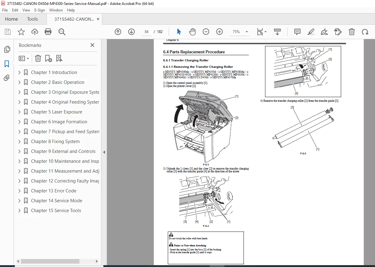
Parts Replacement:
Transfer Charging Roller:
- Roller removal procedure
- Cleaning specifications
- Installation and testing
CHAPTER 7: PICKUP AND FEED SYSTEM
Overview/Configuration:
- Paper feed system overview
- Paper path diagrams
- Feed mechanism operation
Other Control:
- Multipurpose tray control
- Cassette detection
- Paper size detection
Jam Detection:
Jam Detection Outline:
- Detection methodology
- Sensor network
Delay Jams:
- Pickup delay jam – paper doesn’t reach sensor in time
- Delivery delay jam – paper doesn’t exit in time
Stationary Jams:
- Pickup stationary jam – paper stops moving
- Delivery stationary jam – paper stalls at exit
Other Jams:
- Door open jam – door opened during operation
- Wrapping jam – paper wraps around fuser
- Residual jam at startup – paper detected at power-on
Duplex Unit:
- Duplex operation overview
- Reverse path mechanism
- Duplex timing
Parts Replacement:
Main Motor:
- Preparation for removal
- Main motor removal procedure
- Motor testing
Separation Pad:
- Preparation for removal
- Separation pad removal
- Replacement intervals
Pickup Roller:
- Pickup roller removal
- Wear inspection
- Installation procedure
CHAPTER 8: FIXING SYSTEM
Overview/Configuration:
- Specification/Control/Function list
- Fixing system overview
- Film fixing technology
Control Mechanisms:
Fixing Temperature Control:
- Thermistor monitoring
- Heater control circuits
- Temperature regulation
- Warm-up sequence
Protection Function:
- Overheat protection
- Thermistor failure detection
- Safety shutdown procedures
- Error code generation
Parts Replacement:
Fixing Unit:
- Preparation for removal
- Complete fixing assembly removal
- Installation procedures
Fixing Film Unit:
- Preparation for removal
- Film unit removal
- Film replacement
- Heater lamp replacement
CHAPTER 9: EXTERNAL AND CONTROLS
Control Panel:
- Control panel outline
- Button functions
- LED indicators
- LCD display
Power Supply:
Power Supply Route:
- AC input distribution
- DC voltage generation
- Power distribution diagram
Protection Function:
- Overcurrent protection
- Overvoltage protection
- Safety interlocks
Parts Replacement:
Covers:
- Front cover removal
- Rear cover removal (preparation and procedure)
- Right cover removal
- Left cover removal
- Upper cover removal (preparation and procedure)
- Cartridge cover removal
Electronic Components:
Operation Panel Unit:
- Control panel unit removal
- Connector disconnection
- Installation procedures
SCNT Board (Scanner Control Board):
- Preparation for removal
- SCNT PCB removal
- Actions when replacing SCNT PCB (firmware/settings)
DCNT Board (DC Controller Board):
- Preparation for removal
- DCNT PCB removal
- Main controller functions
Power Supply PCB:
- Preparation for removal
- Power supply board removal
- Voltage testing
High-Voltage Power Supply Board:
- Preparation for removal
- High-voltage PCB removal
- Safety precautions
CHAPTER 10: MAINTENANCE AND INSPECTION
Periodically Replaced Parts:
- Parts replacement schedule
- Expected life spans
- Maintenance intervals
Periodical Service:
- Regular service items checklist
- Preventive maintenance schedule
- Inspection procedures
Cleaning:
Cleaning Items:
- Components requiring regular cleaning
- Cleaning frequency
Cleaning Methods:
- External covers cleaning procedures
- Reader unit cleaning (scanner glass, white plate)
- Pressure roller cleaning methods
- Approved cleaning solutions
CHAPTER 11: MEASUREMENT AND ADJUSTMENTS
Basic Adjustments:
Paper Margin Adjustment:
- Top margin setting
- Side margin configuration
- Print position calibration
Reading Adjustment:
- Scanner calibration
- White level adjustment
- Black level adjustment
- Shading correction
Print Adjustment:
- Laser beam positioning
- Registration adjustment
- Density calibration
- Gradation correction
CHAPTER 12: CORRECTING FAULTY IMAGES
Outline of Electrical Components:
Clutch/Solenoid/Motor/Fan:
- List of solenoids/motors (locations and functions)
- Drive specifications
- Testing procedures
Sensors:
- List of sensors (complete sensor inventory)
- Sensor types and locations
- Function descriptions
- Testing methods
PCBs:
- List of PCBs (circuit boards)
- Board locations
- Primary functions
- Interconnections
CHAPTER 13: ERROR CODE
Error Code Outline:
- Error detection system
- Display methods
- Error code format
Error Code:
- Complete error code list with:
- Error number
- Error description
- Probable causes
- Corrective actions
- Component checks
- Testing procedures
CHAPTER 14: SERVICE MODE
Outline:
Setting Service Data:
- Accessing service parameters
- Modification procedures
How to Activate Service Mode:
- Key sequence for entry
- Navigation instructions
- Exiting service mode
Service Data Menu:
- Complete menu structure
- Available options
- Parameter descriptions
Service Soft Switch Settings (SSSW):
SSSW Outline:
- Software switch concept
- Configuration options
- Bit-level settings
Individual SSSW Settings:
- SSSW-SW02 – Function list and bit configurations
- SSSW-SW04 – Function list
- SSSW-SW10 – Function list
- SSSW-SW16 – Function list
- SSSW-SW20 – Function list
- SSSW-SW21 – Function list
- SSSW-SW23 – Function list
- SSSW-SW30 – Function list
- SSSW-SW37 – Function list
- SSSW-SW39 – Function list
- SSSW-SW51 – Function list
- SSSW-SW54 – Function list
Each setting includes detailed bit explanations and functional impact.
Test Mode (TEST):
Test Mode Overview:
- Purpose and applications
- Test mode menu structure
Functionality Tests:
- Print test pattern – diagnostic patterns
- Sensor test – individual sensor verification
- Key test – control panel button testing
- Component diagnostics
CHAPTER 15: SERVICE TOOLS
Service Tools:
- Solvents/Lubricants table:
- Approved cleaning agents
- Lubrication points
- Application methods
- Part numbers for ordering
- Special tools required
- Measurement instruments
- Testing equipment
FILE DETAILS
- Manual Name: Canon MF4300 Series Service Manual
- Models Covered:
- Canon i-SENSYS D450d
- Canon i-SENSYS MF4300dn
- Canon i-SENSYS MF4310/4318
- Canon i-SENSYS MF4320d
- Canon i-SENSYS MF4330d
- Canon i-SENSYS MF4340d
- Canon i-SENSYS MF4350d
- Canon i-SENSYS MF4370dn
- Canon i-SENSYS MF4380dn
- Date: August 22, 2008
- Pages: 182 pages
- PDF Quality: High-quality factory service manual with clear diagrams, exploded views, and technical illustrations
- File Format: Searchable PDF (A4 size)
- Copyright: Canon Inc. 2001
KEY FEATURES OF THIS MANUAL
✓ 182 pages of official Canon factory documentation
✓ 9 MF4300 series models covered comprehensively
✓ Step-by-step disassembly procedures with preparation steps
✓ Complete error code reference with troubleshooting
✓ Service mode documentation with soft switch settings
✓ Detailed parts replacement procedures for all major components
✓ Electrical component lists (motors, sensors, PCBs)
✓ Laser safety information (CDRH compliance)
✓ ADF and DADF service procedures
✓ Image quality troubleshooting guides
✓ Maintenance schedules and cleaning procedures
✓ Adjustment procedures (margins, scanning, printing)
✓ Test mode functions for diagnostics
✓ Exploded view diagrams for component identification
MODELS COVERED IN DETAIL
All-in-One Multifunction Printers:
- Canon i-SENSYS D450d – Compact duplex MFP
- Canon i-SENSYS MF4300dn – Network duplex model
- Canon i-SENSYS MF4310 – Basic MFP
- Canon i-SENSYS MF4318 – Enhanced basic model
- Canon i-SENSYS MF4320d – Duplex printing model
- Canon i-SENSYS MF4330d – Mid-range duplex MFP
- Canon i-SENSYS MF4340d – Advanced duplex model
- Canon i-SENSYS MF4350d – High-performance duplex MFP
- Canon i-SENSYS MF4370dn – Network duplex with advanced features
- Canon i-SENSYS MF4380dn – Top-tier network duplex MFP
Functions:
- Monochrome laser printing
- Copying
- Color scanning
- PC faxing (select models)
- Network printing
- Duplex (automatic two-sided) printing
- ADF/DADF document feeding
WHO NEEDS THIS MANUAL?
- Authorized Canon Service Technicians
- Independent Printer Repair Shops
- Corporate IT Support Teams
- Office Equipment Maintenance Personnel
- Printer Refurbishment Specialists
- Technical Training Centers
- Multi-Vendor Service Organizations
- Fleet Maintenance Departments
CRITICAL SERVICE PROCEDURES INCLUDED
Major Component Replacement:
- Laser scanner unit replacement
- Fixing film unit replacement
- Transfer roller replacement
- Scanner contact sensor replacement
- Main motor replacement
- ADF/DADF motor and roller replacement
Electronic Board Replacement:
- SCNT board (Scanner Controller)
- DCNT board (DC Controller)
- Power supply PCB
- High-voltage power supply board
- Control panel unit
Adjustments & Calibration:
- Print position adjustment
- Scanner reading adjustment
- Laser beam alignment
- Registration correction
- Density calibration
Diagnostics:
- Service mode access and navigation
- Soft switch configuration
- Test mode execution
- Sensor verification
- Error code interpretation
INSTANT DOWNLOAD – MINIMIZE PRINTER DOWNTIME
Stop losing productivity to broken printers! This official Canon factory service manual gives you immediate access to complete repair procedures for nine MF4300 series models. Whether you’re troubleshooting error codes, replacing worn components, or performing preventive maintenance, you’ll have the exact same technical documentation used by Canon authorized service centers worldwide. Download instantly, print the sections you need, and get your Canon MFP back in service quickly with professional-grade factory specifications and procedures!
Pricing Rationale:
This is a comprehensive 182-page official factory service manual covering nine Canon i-SENSYS MF4300 series models – professional multifunction laser printers commonly found in offices, businesses, and corporate environments worldwide. Official manufacturer service manuals for commercial laser printers typically cost $75-150+ from Canon. This manual provides complete technical documentation including disassembly procedures, error code diagnostics, service mode access, parts replacement instructions, and adjustment procedures essential for professional printer repair. The multi-model coverage (9 different MFP models), official factory status, and specialized technical content justify professional pricing. At $29.95, this represents exceptional value for printer technicians, IT departments, and repair shops who need immediate access to complete factory documentation to minimize equipment downtime and avoid costly third-party service calls.