Case 115C Poclain Excavator Service Manual E18-440-29 – PDF DOWNLOAD
Original price was: $75.95.$26.95Current price is: $26.95.
Case 115C Poclain Excavator Service Manual E18-440-29 – PDF DOWNLOAD
Description
Case 115C Poclain Excavator Service Manual E18-440-29 – PDF DOWNLOAD
DESCRIPTION:
Case 115C Poclain Excavator Service Manual E18-440-29 – PDF DOWNLOAD
GENERAL DESCRIPTION :
- The 115 C is a track-mounted hydraulic excavator.
- It is designed for earthmoving operations on all kinds of terrain.
- This machine benefits from the experience acquired from other models in the POCLAIN range, and incorporates
the latest advances as regards both technique and comfort. - Thanks to POCLAIN’S VARIODYN·hydraulic circuit, optimum use is made of the power available, and as a
result a high output can be obtained from this machine. - Owing to the wide range of attachments which can be mounted, the 115 C is a versatile machine, well suited
for earthmoving, rehandling, winning, boring, ditch-cleaning, etc.
TABLE OF CONTENTS:
Case 115C Poclain Excavator Service Manual E18-440-29 – PDF DOWNLOAD
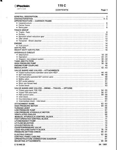
GENERAL DESCRIPTION …… ;………………………………………………. 3
CHARACTERISTICS . . . . . . . . . . . . . . . . . . . . . . . . . . . . . . . . . . . . . . . . . . . . . . . . . . . . . . . . . . . . . . . . 4 – 5
UPPERSTRUCTURE – CARRIER FRAME
• Upperstructure . . . . . . . . . . . . . . . . . . . . . . . . . . . . . . . . . . . . . . . . . . . . . . . . . . . . . . . . . . . . . . . . . . . 6
• Carrier frame. . . . . . . . . . . . . . . . . . . . . . . . . . . . . . . . . . . . . . . . . . . . . . . . . . . . . . . . . . . . . . . . . . . . . 7
• Swing gear. . . . . . . . . . . . . . . . . . . . . . . . . . . . . . . . . . . . . . . . . . . . . . . . . . . . . . . . . . . . . . . . . . . . . . . 8
TRACK GROUP
• Tracks – Pads… . . . . . . . . . . . . . . . . . . . . . . . . . . . . . . . . . . . . . . . . . . . . . . . . . . . . . . . . . . . . . . . . . . 9
• Rollers………………………………………………………………. 10
• Sprocket wheel reduction gear . . . . . . . . . . . . . . . . . . . . . . . . . . . . . . . . . . . . . . . . . . . . . . . . . . . . . . 11
• Idler wheel . . . . . . . . . . . . . . . . . . . . . . . . . . . . . . . . . . . . . . . . . . . . . . . . . . . . . . . . . . . . . . . . . . . . . 12
• Tensioner – Shock absorber. . . . . . . . . . . . . . . . . . . . . . . . . . . . . . . . . . . . . . . . . . . . . . . . . . . . . . . . . 12
ENGINE………………………………………………………………… 14
• Fuel circuit……………………………………………… . . . . . . . . . . . . . . . 14
AIR FILTER……………………………………………………………… 15
HEAVYDUTYAIRFILTER ………………………………………………….. 16
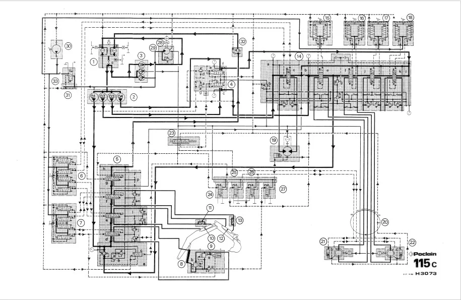
HYDRAULIC CIRCUIT
• Description . . . . . . . . . . . . . . . . . .. . . . . . . . . . . . . . . . . . . . . . . . . . . . . . . . . . . . . . . . . . . . . . . . . 18 – 20
• Operation . . . . . . . . . . . . . . . . . . . . . . . . . . . . . . . . . . . . . . . . . . . . . . . . . . . . . . . . . . . . . . . . . . . 22 – 31
• Diagram, low pressure system . . . . . . . . . . . . . . . . . . . . . . . . . . . . . . . . . . . . . . . . . . . . . . . . . . . . 32 – 34
TANK AND FILTERS . . . . . . . . . . . . . . . . . . . . . . . . . . . . . . . . . . . . . . . . . . . . . . . . . . . . . . . . . . . . . ·35 – 37
HIGH PRESSURE PUMP ………………………………………………….. 38- 39
ENGINE-PUMP COUPLING. . . . . . . . . . . . . . . . . . . . . . . . . . . . . . . . . . . . . . . . . . . . . . . . . . . . . . . . . . . . 40
MODULATOR …………………………………………………………. 42-43
VALVE BAN KS AND VALVES – ATTACHMENTS
• Fitted hydraulically-operated valve bank 4S27………………………………… 44 -45
• S27 inlet block . . . . . . . . . . . . . . . . . . . . . . . . . . . . . . . . . . . . . . . . . . . . . . . . . . . . . . . . . . . . . . . 46 -48
• Hydraulically-operated S27 control valve . . . . . . . . . . . . . . . . . . . . . . . . . . . . . . . . . . . . . . . . . . . . . . 49
• Safety valve. . . . . . . . . . . . . . . . . . . . . . . . . . . . . . . . . . . . . . . . . . . . . . . . . . . . . . . . . . . . . . . . . . . . . 50
• S27 outlet selector . . . . . . . . . . . . . . . . . . . . . . . . . . . . . . . . . . . . . . . . . . . . . . . . . . . . . . . . . . . . . . . 51
• Stick ram forced feed . . . . . . . . . . . . . . . . . . . . . . . . . . . . . . . . . . . . . . . . . . . . . . . . . . . . . . . . . . . . . 52
• Outlet block . . . . . . . . . . . . . . . . . . . . . . . . . . . . . . . . . . . . . . . . . . . . . . . . . . . . . . . . . . . . . . . . . . . . 53
VALVE BANKS AND VALVES-SWING -TRAVEL-OPTIONS
• Fitted vaive bank T20. P20 . . . . . . . . . . . . . . . . . . . . . . . . . . . . . . . . . . . . . . . . . . . . . . . . . . . . . . 54 – 55
• Fitted T20 valve bank . . . . . . . . . . . . . . . . . . . . . . . . . . . . . . . . . . . . . . . . . . . . . . . . . . . . . . . . . . 56 – 57
• P20 control valve …….. ; . . . . . . . . . . . . . . . . . . . . . . . . . . . . . . . . . . . . . . . . . . . . . . . . . . . . . 58 – 59
• Inlet block……………….. . . . . . . . . . . . . . . . . . . . . . . . . . . . . . . . . . . . . . . . . . . . . . . . . . . 60
• Counterpressure valve…………………………………………… . . . . . . . . . . 60
• Intermediate block – Inlet block . . . . . . . . . . . . . . . . . . . . . . . . . . . . . . . . . . . . . . . . . . . . . . . . . . . . . 61
ATTACHMENT RAMS ……………………………………………………. 62-63
HIGH PRESSURE MOTOR . . . . . . . . . . . . . . . . . . . . . . . . . . . . . . . . . . . . . . . . . . . . . . . . . . . . . . . . . 64 -65
TURNING JOINT . • . • • . . . . . . . . . • . . . • . . . . . . . . . . . • . . . . . . . . . . . . . . . . . . . . . . . . . . . . . . . . . . . . 66
LOW PRESSURE PUMP ………….. ;………………………………………… 67
LOW PRESSURE HYDRAULIC MOTOR. . . . . . . . . . . . . . . . . . . . . . . . . . . . . . . . . . . . . . . . . . . . . . . . . . 68
VENTILATED COOLER . . . . . . . . . . . . . . . . . . . . . . . . . . . . . . . . . . . . . . . . . . . . . . . . . . . . . . . . . . . . . . 69
MANUAL HYDRAULIC CONTROL BLOCK. • . . . . . . . . . . . . . . . . . . . . . . . . . . . . . . . . . . . . . . . . . . . . . 70
FOOT-OPERATED CONTROL BLOCK…………………………………………… 71
LP EMERGENCY PUMP……………………………………………………… 72
LP FLOW SELECTOR………………………………………………………. 73
LP ELECTROVALVE……………………………………………………….. 74
COUNTERPRESSURE VALVE…………………………………………………. 75
LOAD HOLDING SAFETY BLOCK. . . . . . . . . . . . . . . . . . . . . . . . . . . . . . . . . . . . . . . . . . . . . . . . . . . 76 -79
PRESSURE-SETTING CHECK. . . . . . . . . . . . . . . . . . . . . . . . . . . . . . . . . . . . . . . . . . . . . . . . . . . . . . . 80 – 81
ELECTRIC CIRCUIT …………………………………………………….. 82 -85
CONTROL PANEL CABLING . . . . . . . . . . . . . . . . . . . . . . . . . . . . . . . . . . . . . . . . . . . . . . . . . . . . . . . . . . 86
UPPERSTRUCTURE CONNECTION DIAGRAM . . . . . . . . . . . . . . . . . . . . . . . . . . . . . . . . . . . . . . . . . . . 87
MOUNTING ATTACHMENTS……….. . . . . . . . . . . . . . . . . . . . . . . . . . . . . . . . . . . . . . . . . . . . . 88 – 89
IMAGES PREVIEW OF THE MANUAL:
CASE 115C POCLAIN EXCAVATOR SERVICE MANUAL E18-440-29 – PDF DOWNLOAD:
PLEASE NOTE:
- This is the SAME MANUAL used by the dealerships to diagnose your vehicle
- No waiting for couriers / posts as this is a PDF manual and you can download it within 2 minutes time once you make the payment.
- Your payment is all safe and the delivery of the manual is INSTANT – You will be taken to the DOWNLOAD PAGE.
- So have no hesitations whatsoever and write to us about any queries you may have : heydownloadss @gmail.com
S.V