Case 15 & 16 Mini Excavator Service Manual 7-83210 – PDF DOWNLOAD
Original price was: $89.95.$27.95Current price is: $27.95.
Case 15 & 16 Mini Excavator Service Manual 7-83210 – PDF DOWNLOAD
Description
Case 15 & 16 Mini Excavator Service Manual 7-83210 – PDF DOWNLOAD
DESCRIPTION:
Case 15 & 16 Mini Excavator Service Manual 7-83210 – PDF DOWNLOAD
USING THE SERVICE MANUAL
Manual introduction:
The purpose of this manual is to assist Dealers and Distributors with the efficient repair and maintenance of the 15 and 16 Mini-excavators. Following the procedures as detailed together with using the special tools where appropriate, will enable the operations to be completed within the time stated in the Repair Time Schedule CRTS).
The structure of the manual :
This manual has been divided into 1 5 Chapters using the same numbering system as the Operator’s Book and the Parts Catalogue. Each Chapter is divided into three Sections. The three Sections are Data, Maintenance and Troubleshooting. Some Sections are further divided into Sub-sections. The Contents at the front of this manual lists all Chapters, Sections and Sub-sections with corresponding page numbers using the following numbering system for identification.
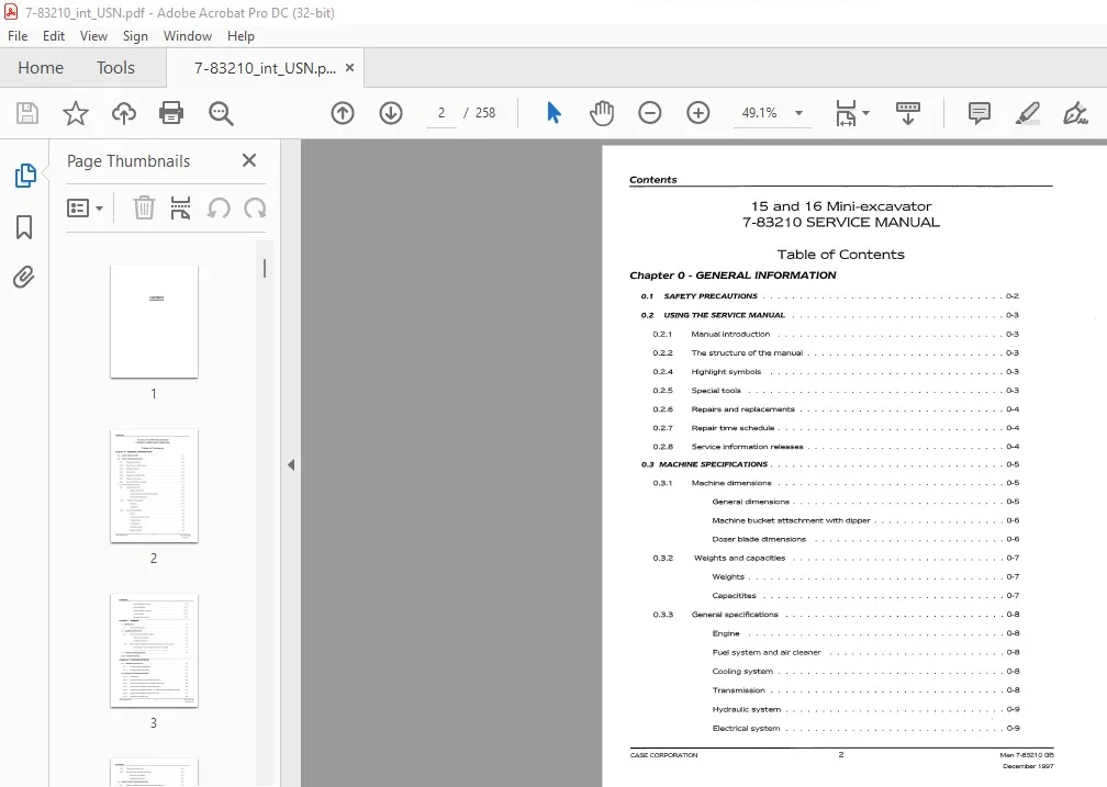
TABLE OF CONTENTS:
Case 15 & 16 Mini Excavator Service Manual 7-83210 – PDF DOWNLOAD
Chapter O – GENERAL INFORMATION
01 SAFETY PRECAUTIONS
OZ USING THE SERVICE MANUAL
Manual introduction
The structure of the manual
Highlight symbols
Special tools
Repairs and replacements
Repair time schedule
Service information releases
03 MACHINE SPECIFICATIONS
031 Machine dimensions
General dimensions
Machine bucket attachment with dipper
Dozer blade dimensions
032 Weights and capacities
Weights
Capacitites
033 General specifications
Engine
Fuel system and air cleaner
Cooling system
Transmission
Hydraulic system
Electrical system
CASE CORPORATION 2
Permissible temperature
Lifting capacities
Recommended lubricants
Torque Figures
Maintenance schedule
Chapter 1 – ENGINE
11 ENGINE DATA
111 Engine specifications
12 ENGINE MAINTENANCE
121 Removing and installing the engine
Removing the engine
Installing the engine
122 Removing and installing the main hydraulic pump drive coupling
Removing the main hydraulic pump drive coupling
Installing the main hydraulic pump drive coupling
13 ENGINE TROUBLESHOOTING
Annex A ENGINE MANUAL
Chapter 2 – COOLING SYSTEM
21 COOUNG SYSTEM DATA
Cooling system specifications
Cooling system torque data
22 COOUNG SYSTEM MAINTENANCE
Introduction
Principle of operation of the cooling system
Checking and topping up the engine coolant level
Checking and adjusting the fan belt tension
Checking the antifreeze solution – for interval see Maintenance Schedule
Checking the operation of the thermostat
Checking the radiator cap
CASE CORPORATION 3
Cleaning the radiator fins
Removing and installing the radiator
Removing the radiator
Installing the radiator
Z3 COOLING SYSTEM TROUBLESHOOTING
231 Engine overheats (coolant temperature lamp comes on)
Chapter 3 – FUEL, AIR AND EXHAUST
31 FUEL, AIR, AND EXHAUST DATA
311 Fuel, air, and exhaust specifications
Lovv pressure fuel system
Air system
312 Fuel, air, and exhaust torque data
32 FUEL, AIR, AND EXHAUST MAINTENANCE
321 Principle of operation of the fuel, air, and exhaust systems
Fuel (lovv pressure)
Air
Exhaust
Replacing the fuel filter
Draining condensate from the fuel tank
Draining the agglomerator
Venting air from the fuel system
Removing and installing the fuel tank
Removing the fuel tank
Installing the fuel tank
Cleaning the air filter element
Replacing the air filter element
Replacing the exhaust system
CASE CORPORATION 4
33 FUEL AIR AND EXHAUST TROUBLESHOOTING
Starter motor turns but engine does not start
Fuel level lamp comes on
Air filter lamp comes on
Engine stalls when speed is low
Insufficient power
Fuel consumption high
Black exhaust smoke
Blue or white exhaust smoke
Chapter 4 – TRACK GEARBOX
41 TRACKGEARBOXDATA
Track gearbox specifications
Track gearbox torque data
42 TRACK GEARBOX MAINTENANCE
Principle of operation of the track gearbox
Checking the track gearbox oil level
Changing the track gearbox oil
Removing and installing the track gearbox
Removing the track gearbox
Installing the track gearbox
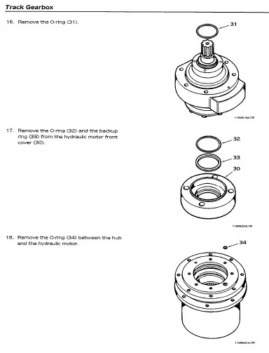
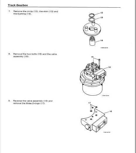
Disassembling, inspecting, and assembling the track gearbox
Disassembling the track gearbox
Inspecting the track gearbox after disassembly
Assembling the track gearbox
43 TRACK GEARBOX TROUBLESHOOTING
The track gearbox does not turn
Turning is not stable
Direction of rotation is reversed
Oil leaks from joints
CASE CORPORATION 5
Chapter S – BRAKES
This chapter is not applicable to the 15 and 16 mini excavators
Chapter 6 – TRACK, FRAME AND UNDERCARRIAGE
61 TRACK, FRAME, AND UNDERCARRIAGE DATA
Track, frame, and undercarriage specifications
Track, frame, and undercarriage torque data
Track, frame, and undercarriage wear limits
Rubber track
Metal track
Lower roller
Drive sprocket
Idler
Track tension
62 TRACK, FRAME, AND UNDERCARRIAGE MAINTENANCE
Component identification
Cleaning the tracks
Removing, inspecting, and installing the rubber tracks
Removing the rubber track
Inspecting the rubber track
Installing the rubber track
Removing, inspecting, and installing the metal tracks
Removing the metal track
Inspecting the metal track
Installing the metal track
Adjusting the track tension
Removing and installing the lower roller
Removing the lower roller
Installing the lower roller
CASE CORPORATION 6
Disassembling, inspecting, and assembling the lovver roller
Disassembling the lovver roller
Inspecting the lovver roller
Assembling the lovver roller
Removing and installing the idler and track tensioner
Removing the idler and track tensioner
Installing the idler and track tensioner
Disassembling, inspecting, and assembling the idler and track tensioner
Disassembling the idler and track tensioner
Inspecting the idler
Inspecting the track tensioner
Assembling the idler and track tensioner
Removing, inspecting, and installing the sprocket
Removing the sprocket
Inspecting the sprocket
Installing the sprocket
Removing and installing the dozer blade
Removing the dozer blade
Installing the dozer blade
Adjusting the track lever stroke
63 TRACK, FRAME, AND UNDERCARRIAGE TROUBLESHOOTING
Machine vvill not move in a straight line
Excessive vvear of sprocket
Chapter 7 – CAB AND CANOPY
71 CAB AND CANOPY DATA
Cab and canopy specifications
Cab and canopy torque data
72 CAB AND CANOPY MAINTENANCE
721 General information
Removing and installing the cab or ROPS
Removing the cab or ROPS
Installing the cab or ROPS
Removing and installing the canopy
Removing the canopy
Installing the canopy
Checking the mounting integrity
Replacing the cab glazing
73 CAB OR CANOPY TROUBLESHOOTING
This section is not applicable to the cab and canopy
Chapter 8 – SHEET METAL AND COVERS
81 SHEET METAL AND COVERS DATA 8-2
This section is not applicable to sheet metal and covers
82 SHEET METAL AND COVERS MAINTENANCE
821 Sheet metal and covers identification
822 Removing and installing the covers and the seat
CASE CORPORATION
General
Removing the engine cover
Removing the rear guard
Removing the floor plate
Removing the seat
Removing the bulkhead
Removing the side cover
Removing the seat under tray
Removing the side moulding
Installing the side moulding
Installing the seat under tray
Installing the side cover
Installing the bulkhead
Installing the seat
Installing the floor plate
Installing the rear guard
Installing the engine cover
83 SHEET METAL AND COVERS TROUBLESHOOTING
This section is not applicable to sheet metal and covers
Chapter 9 – ELECTRICAL SYSTEM
91 ELECTRICAL SYSTEM DATA
Electrical system specifications
Electrical system torque data
92 ELECTRICAL SYSTEM MAINTENANCE
Principle of operation of the electrical system
Removing and installing the alternator
Removing the alternator
Installing the alternator
Removing and installing the starter motor
Removing the starter motor
Installing the starter motor
Removing and installing the instrument cluster
Removing the instrument cluster
Installing the instrument cluster
Removing and installing the battery
Removing the battery
Installing the battery
Removing and insalling the starter switch
Removing the starter switch
Installing the starter switch
Removing and installing relays
Removing relays
Installing relays
Removing and installing the heater
Removing the heater
Installing the heater
Removing and installing the wiper motor
Removing the wiper motor
Installing the wiper motor
Disassembling, inspecting, and assembling the alternator
Testing the alternator
Disassembling, inspecting, and assembling the starter motor
Disassembling and assembling the instrument cluster
93 ELECTRICAL SYSTEM TROUBLESHOOTING
Starter motor will not tum engine
Battery specific gravity reading low
Alternator not charging
Wash and wipe inoperative
Heater will not operate
Work lamp inoperative
Beacon inoperative
Circuits inoperative
Chapter 10 – HYDRAULIC SYSTEM (EXCEPT CYLINDERS)
101 HYDRAULIC SYSTEM DATA
Hydraulic system specifications
Hydraulic system torque data
Control valve
Swivel joint
Main hydraulic pump
Hydraulic system special tools
Principle of operation of the hydraulic system
Hydraulic circuit
Main hydraulic pump
Control valve
Main relief valve
Port relief valve
Anti-cavitation valve
Solenoid valve
Servo controller
Servo control system
Swivel joint
Checking the hydraulic oil level
Changing the hydraulic oil
Replacing the return filter cartridge
Pressurising the hydraulic tank
Venting air from the hydraulic system
Removing and installing the hydraulic tank
Removing the hydraulic tank
Installing the hydraulic tank
Removing and installing the main hydraulic pump
Removing the main hydraulic pump
Installing the main hydraulic pump
Replacing the main hydraulic pump seals
Removing and installing the auxiliary hydraulic pump
Removing the auxiliary hydraulic pump
Installing the auxiliary hydraulic pump
Replacing the auxiliary hydraulic pump seals
Removing and installing the control valve
Removing the control valve
Installing the control valve
Replacing the main and port relief valve seals
Replacing the anti-cavitation valve seal
Replacing the spool seals (manually operated section)
Replacing the spool seals (servo operated section)
Replacing the spool seal (spacer section)
1 02 18 Replacing the control valve seals
Removing and installing the solenoid valve
Removing the solenoid valve
Installing the solenoid valve
Replacing the solenoid valve seals
Removing and installing the servo controller
Removing the servo controller
Installing the servo controller
Replacing the servo controller seals
Removing and installing the swivel joint
Removing the swivel joint
Installing the swivel joint
Replacing the swivel joint seals
Selector
Swivel joint
Inspecting the swivel joint after assembly
Adjusting the main relief valve set pressure
Adjusting the solenoid valve relief set pressure
Checking operation of the main hydraulic pump
Checking the main hydraulic pump discharge volume
Post-assembly test of the main hydraulic pump
Adjusting the port relief valve CPRV) set pressure
Adjusting the slevv cross line relief valve (CLRV) set pressure
103 HYDRAULIC SYSTEM TROUBLESHOOTING
Main hydraulic pump
Pump vvill not discharge oil
Noise level is high
Oil leaks from oil seals
Oil leaks from between housing and flange or cover
Discharge volume is lovv
Control valve
Oil leaks from spool seal
Spool sliding movement not smooth
Cylinder drops vvhen shifting to a lifting operation
Cylinder drops (vvill not hold in spool neutral position)
Load vvill not move (pressure vvill not increase)
Load does not move (pressure rises)
Solenoid valve
Solenoid valve does not operate
Servo controllers
Secondary pressure does not rise
Secondary pressure does not stabilise
Secondary pressure is high
Swivel joint
External oil leakage
Internal oil leakage
Chapter 11 – LOADER
Chapter 12 – BOOM, DIPPER, AND LINKAGE
121 BOOM DIPPER AND LINKAGE DATA
1211 Boom, dipper, and linkage specifications
Bucket
Boom
Dipper
122 BOOM DIPPER AND LINKAGE MAINTENANCE
Greasing the pivot pins, the pedals, and the levers
Removing and installing the bucket
Removing the bucket
Installing the bucket
Removing and installing the bucket link
Removing the bucket link
Installing the bucket link
Removing and installing the dipper
Removing the dipper
Installing the dipper
Removing and installing the boom
Removing the boom
Installing the boom
Removing and installing the king post support, off-set arm, and linkage
Removing the king post support, off-set arm, and linkage
Installing the king post support, off-set arm, and linkage
123 BOOM, DIPPER AND LINKAGE TROUBLESHOOTING
Chapter 13 – HYDRAULIC CYLINDERS
131 HYDRAULIC CYLINDERS DATA
13 1 1 Hydraulic cylinders specifications
Boom cylinder
Dipper cylinder
Dozer blade cylinder
Bucket cylinder
Off-set cylinder
Track widening cylinder
Principle of operation of hydraulic cylinders (Typical)
Removing and installing cylinders
Removing cylinders
Installing the cylinders
Disassembling, inspecting, and assembling cylinders (Typical)
Disassembling cylinders
Inspecting cylinders after disassembly
Assembling cylinders
Inspecting cylinders after assembly
Cylinder leak test
External leak test
Internal leak test
Venting air from a hydraulic cylinder
133 HYDRAULIC CYLINDER TROUBLESHOOTING
Oil leaks from piston rod sliding surface
Oil leaks from the outer circumference of the rod cover
Cylinder natural fall is 05 mm or greater
Boom or dipper cylinder will not operate or operation is slow or there
is no power
Off-set cylinder will not operate
Bucket cylinder does not move or there is no power
Dozer blade or track widening cylinder does not move or there is
no power
Boom drops temporarily when operating lever is pulled gently
Boom cylinder natural fall is excessive
133 1 0 Dipper or bucket cylinder natural fall is excessive
133 11 Dozer blade cylinder natural fall is excessive or dozer blade will not
hold up the machine
Chapter 14 – SUPERSTRUCTURE (INCLUDING SLEW MOTOR)
141 SUPERSTRUCTURE (INCLUDING SLEW MOTOR DATA)
Superstructure (including slew motor) specifications
Superstructure (including slew motor) torque data
142 SUPERSTRUCTURE (INCLUDING SLEW MOTOR) MAINTENANCE
1421 Principle of operation of slewing
Slew bearing
Slew motor
Relief valve
1422 Removing and installing the superstructure
Removing the superstructure
Installing the superstructure
1423 Removing and installing the control lever stands
Removing the control lever stands
Installing the control lever stands
1424 Removing and installing the slew motor
Removing the slew motor
Installing the slew motor
1425 Removing and installing the slew bearing (ring)
Removing the slew bearing
Installing the slew bearing
1426 Disassembling, inspecting, and assembling the slew motor
Disassembling the brake valve
Disassembling the slew motor
Inspecting the brake valve
Inspecting the slew motor
Assembling the slew motor
Assembling the brake valve
143 SUPERSTRUCTURE (INCLUDING SLEW MOTOR) TROUBLESHOOTING
Slew motor does not tum
Slewing is not stable
Direction of rotation is reversed
Oil leaking from joints
Chapter 15 – DECALS
151 DECALS DATA
1511 Safety decals
152 DECALS MAINTENANCE
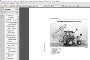
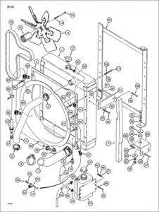
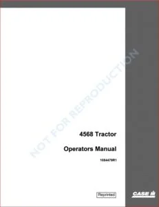
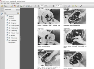
IMAGES PREVIEW OF THE MANUAL:
CASE 15 & 16 MINI EXCAVATOR SERVICE MANUAL 7-83210 – PDF DOWNLOAD:
PLEASE NOTE:
- This is the SAME exact manual used by your dealers to fix your vehicle.
- The same can be yours in the next 2-3 mins as you will be directed to the download page immediately after paying for the manual.
- Any queries / doubts regarding your purchase, please feel free to contact [email protected]
S.V