Case 28 31 35 Mini Excavator Service Manual 7-83260 – PDF DOWNLOAD
Original price was: $88.95.$28.95Current price is: $28.95.
Case 28 31 35 Mini Excavator Service Manual 7-83260 – PDF DOWNLOAD
Description
Case 28 31 35 Mini Excavator Service Manual 7-83260 – PDF DOWNLOAD
DESCRIPTION:
Case 28 31 35 Mini Excavator Service Manual 7-83260 – PDF DOWNLOAD
USING THE SERVICE MANUAL :
Manual introduction
- The purpose of this manual is to assist Dealers and Distributors with the efficient repair and maintenance of the 28, 31 and 35 mini-excavators.
- Following the procedures as detailed together with using the special tools where appropriate, will enable the operations to be completed within the time stated in the Repair Time Schedule CRTS).
The structure of the manual :
- This manual has been divided into 1 5 Chapters using the same numbering system as the Operator’s Book and the Parts Catalogue. Each Chapter is divided into three Sections.
- The three Sections are Data, Maintenance and Troubleshooting. Some Sections are further divided into Sub-sections. The Contents at the front of this manual lists all Chapters, Sections and Sub-sections with corresponding page numbers using the following numbering system for identification.
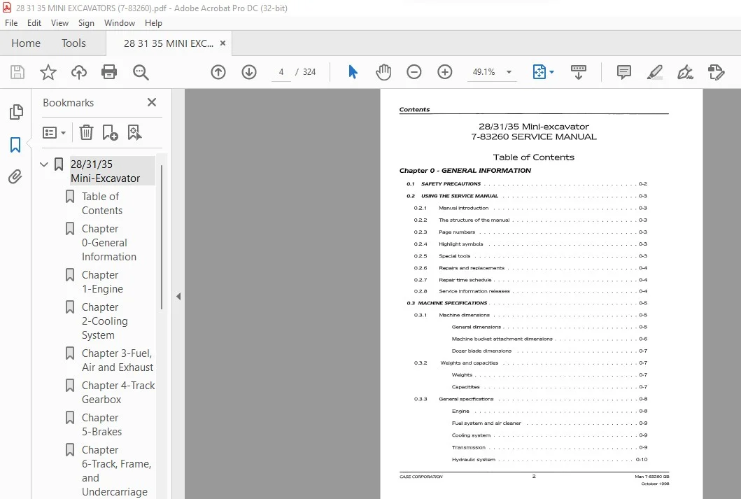
TABLE OF CONTENTS:
Case 28 31 35 Mini Excavator Service Manual 7-83260 – PDF DOWNLOAD
Chapter O – GENERAL INFORMATION
0.1 SAFETY PRECAUTIONS . . . .
0.2 USING THE SERVICE MANUAL
0.2.1 Manl!al introduction
0.2.2 The structure of the manual
0.2.3 Page numbers
0.2.4 Highlight symbols
0.2.5 Special tools
0.2.6 Repairs and replacements
0.2.7 Repair time schedule .
0.2.8 Service information releases
0.3 MACHINE SPECIFICATIONS .
0.3.1 Machine dimensions
General dimensions .
Machine bucket attachment dimensions .
Dozer blade dimensions
0.3.2 Weights and capacities
Weights ..
Capacitites
0.3.3 General specifications
Engine
Fuel system and air cleaner
Cooling system
Transmission .
Hydraulic system
Electrical system . . . .
Permissible temperature
Lifting capacities
General torque figures
Recommended lubricants
Maintenance schedule
Chapter 1 – ENGINE
1.1 ENGINE DATA . …
1.1.1 Engine specifications
1.2 ENGINE MAINTENANCE . .
1.2.1 Removing and installing the engine
Removing the engine
Installing the engine .
1.2.2 Removing and installing the main hydraulic pump drive coupling
Removing the main hydraulic pump drive coupling
Installing the main hydraulic pump drive coupling
1.3 ENGINE TROUBLESHOOTING
Annex A ENGINE MANUAL
Chapter 2 – COOLING SYSTEM
2.1 COOLING SYSTEM DATA
Cooling system specifications
Cooling system torque data
2.2 COOLING SYSTEM MAINTENANCE
Introduction
Principle of operation of the cooling system
Checking and topping up the engine coolant level
Checking and adjusting the fan belt tension
Checking the antifreeze solution . . . . .
Checking the operation of the thermostat
Checking the radiator cap
Cleaning the radiator fins
Removing and installing the radiator and oil cooler
Removing the radiator and oil cooler
Installing the radiator and oil cooler
2.3 COOLING SYSTEM TROUBLESHOOTING
2.3.1 Engine overheats
Chapter 3 – FUEL, AIR, AND EXHAUST
3.1 FUEL, AIR, AND EXHAUST DATA . . . . .
3.1.1 Fuel, air, and exhaust specifications
Low pressure fuel system
Air system
3.1.2 Fuel, air, and exhaust torque data
3.2 FUEL, AIR, AND EXHAUST MAINTENANCE
3.2.1 Principle of operation of the fuel, air, and exhaust systems .
Fuel Oow pressure)
Air
Exhaust.
Replacing the fuel filter
Draining condensate from the fuel tank
Draining the agglomerator . . . .
Venting air from the fuel system
Removing and installing the fuel tank
Removing the fuel tank .
Installing the fuel tank .
Cleaning the main air filter element
Replacing the air filter element
Replacing the exhaust system .
3.3 FUEL, AIR, AND EXHAUST TROUBLESHOOTING
Starter motor turns but engine does not start .
Fuel level lamp comes on .
Air filter lamp comes on
Engine stalls when speed is low
Insufficient power
Fuel consumption high
Black exhaust smoke .
Blue or white exhaust smoke
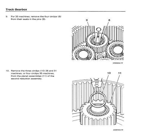
Chapter 4 – TRACK GEARBOX
4.1 TRACK GEARBOX DATA
Track gearbox specifications
Track gearbox torque data
4.2 TRACK GEARBOX MAINTENANCE
Principle of operation of the track gearbox (Typical)
Axial piston type hydraulic motor .
Control valve
Checking the track gearbox oil level
Changing the track gearbox oil . . .
Removing and installing the track gearbox
Removing the track gearbox
Installing the track gearbox .
Disassembling, inspecting, and assembling the track gearbox
Disassembling the track gearbox
Inspecting the track gearbox .
Assembling the track gearbox
4.3 TRACK GEARBOX TROUBLESHOOTING
Direction of rotation is reversed
Oil leaks from joints
Chapter S – BRAKES
The track and slew brakes are included in their respective motor and reduction sections.
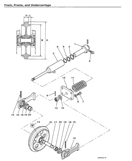
Chapter 6 – TRACK, FRAME, AND UNDERCARRIAGE
6.1 TRACK, FRAME, AND UNDERCARRIAGE DATA . . . .
Track, frame, and undercarriage specifications
Track, frame, and undercarriage torque data
Track, frame, and undercarriage wear limits
Rubber track
Metal track .
Lower roller .
Drive sprocket
Idler ….
Upper roller
Track tensioner .
6.2 TRACK, FRAME, AND UNDERCARRIAGE MAINTENANCE
Component identification
Cleaning the tracks
Removing, inspecting, and installing the rubber tracks
Removing the rubber track .
Inspecting the rubber track
Installing the rubber track
Removing, inspecting, and installing the metal tracks.
Removing the metal track
Inspecting the metal track
Installing the metal track
Adjusting the track tension
Removing and installing the lower roller
Removing the lower roller .
Installing the lower roller .
Disassembling, inspecting, and assembling the lower roller
Disassembling the lower roller
Inspecting the lower roller
Assembling the lower roller
Removing and installing the upper roller
Removing the upper roller
Installing the upper roller .
Disassembling, inspecting, and assembling the upper roller
Disassembling the upper roller
Inspecting the upper roller
Assembling the upper roller .
Removing and installing the idler and track tensioner
Removing the idler and track tensioner
Installing the idler and track tensioner .
Disassembling, inspecting, and assembling the idler and track tensioner
Disassembling the idler and track tensioner
Inspecting the idler and track tensioner
Assembling the idler and track tensioner
Removing, inspecting, and installing the sprocket
Removing the sprocket
Inspecting the sprocket
Installing the sprocket
Removing and installing the dozer blade
Removing the dozer blade
Installing the dozer blade .
Adjusting the track lever stroke
6.3 TRACK, FRAME, AND UNDERCARRIAGE TROUBLESHOOTING
Machine will not move in a straight line
Excessive wear of sprocket
Chapter 7 – CAB AND ROPS
7.1 CABANDROPSDATA …..
Cab and ROPS specifications
Cab and ROPS torque data
7.2 CAB AND ROPS MAINTENANCE
General information . .
Removing and installing the cab or ROPS
Removing the cab or ROPS
Installing the cab or ROPS .
Checking the mounting integrity .
Replacing the cab glazing
7.3 CAB OR ROPS TROUBLESHOOTING
This section is not applicable to the cab or ROPS.
Chapter 8 – SHEET METAL AND COVERS
8.1 SHEET METAL AND COVERS DATA . . . . . . . . . . . . . . . . . . . . . . . . . .. 8-2
This section is not applicable to sheet metal and covers.
8.2 SHEET METAL AND COVERS MAINTENANCE
8.2.1 Identification of covers .
External covers ..
28 Internal covers
31 /35 Internal covers
8.2.2 Removing and installing the covers and the seat
General ………. .
Removing the engine cover
Removing the bumpers
Removing the bulkhead
Removing the counterweight
Removing the sump guard
Removing the seat . . . .
Removing the suspension from the seat
Removing the bracket assembly
Removing the seat support .
Removing the foot rest
Removing the tool box
Removing the floor plate
Installing the floor plate
Installing the tool box .
Installing the foot rest
Installing the seat support
Installing the bracket assembly .
Installing the suspension on the seat .
Installing the seat . . . .
Installing the sump guard
Installing the counterweight
Installing the bulkhead
Installing the bumpers
Installing the engine cover
8.3 SHEET METAL AND COVERS TROUBLESHOOTING
This section is not applicable to sheet metal and covers.
Chapter 9 – ELECTRICAL SYSTEM
9.1 ELECTRICAL SYSTEM DATA . . . . . .
Electrical system specifications
Electrical system torque data
9.2 ELECTRICAL SYSTEM MAINTENANCE
9.2.1 Principle of operation of the electrical system
Removing and installing the alternator
Removing the alternator
Installing the alternator .
Removing and installing the starter motor
Removing the starter motor
Installing the starter motor .
Removing and installing the instrument cluster
Removing the instrument cluster
Installing the instrument cluster
Removing and installing the battery
Removing the battery
Installing the battery .
Removing and installing the starter switch
Removing the starter switch
Installing the starter switch
Removing and installing relays
Removing a relay
Installing a relay
Removing and installing the heater
Removing the heater
Installing the heater
Removing and installing the wiper motor
Removing the wiper motor
Installing the wiper motor
Disassembling, inspecting, and assembling the alternator
Testing the alternator . . . . . . . . . . . . . . . . . . .
Disassembling, inspecting, and assembling the starter motor
Disassembling and assembling the instrument cluster . . . .
9.3 ELECTRICAL SYSTEM TROUBLESHOOTING
Starter motor will not tum engine .
Battery specific gravity reading low
Alternator not charging . . .
Wash and wipe inoperative .
Heater will not operate
Worklamp inoperative
Beacon inoperative
Circuits inoperative
Chapter 10 – HYDRAULIC SYSTEM (EXCEPT CYLINDERS)
10.1 HYDRAULIC SYSTEM DATA
Hydraulic system specifications
Hydraulic system torque data
Control valve
Main hydraulic pump
Hydraulic system special tools
10.2 HYDRAULIC SYSTEM MAINTENANCE
28 Hydraulic Circuit Diagram (up to Ser No. DBK0005010)
28 Hydraulic Circuit Diagram (from Ser No. DBK0005010) .
31/35 Hydraulic Circuit Diagram (31, up to Ser No. DBK0006026/
35, up to Ser No. DBK0007002)
31/35 Hydraulic Circuit Diagram (31, from Ser No. DBK0006026/ …. 10-8
35, from Ser No. DBK0007002)
10.2.1 Principle of operation of the hydraulic system and components .
Main hydraulic pump
Control valve (28) . .
Control valve (31 and 35)
Control valve operation .
Straight line travel function
Dipper-in function .
Two speed slew function
Main relief valve
Port relief valve .
Anti-cavitation valve
Solenoid valve
Servo controllers
Servo control system .
Swivel joint . . . . . .
Checking the hydraulic oil level .
Changing the hydraulic oil
Replacing the retum filter cartridge
Pressurising the hydraulic tank
Venting air from the hydraulic system
Removing and installing the hydraulic tank
Removing the hydraulic tank
Installing the hydraulic tank
Removing and installing the main hydraulic pump
Removing the main hydraulic pump
Installing the main hydraulic pump .
Replacing the main hydraulic pump seals
Removing and installing the auxiliary hydraulic pump
Removing the auxiliary hydraulic pump
Installing the auxiliary hydraulic pump .
Replacing the auxiliary hydraulic pump seals
Removing and installing the control valve
Removing the control valve
Installing the control valve .
Replacing the main and port relief valve seals
1 0.2. 14 Replacing the anti-cavitation valve seals
Replacing a load check valve seal (31 and 35 only)
Replacing the spool seals (manually operated section)
Replacing the spool seals (servo operated section)
Replacing the slew flow control seals
Replacing the travelling and straight travelling spool seals
Replacing the control valve seals . . . . . .
Removing and installing the solenoid valve
Removing the solenoid valve
Installing the solenoid valve .
Replacing the solenoid valve seals
Removing and installing the servo controller .
Removing the servo controller
Installing the servo controller .
Replacing the servo controller seals
Removing and installing the swivel joint
Removing the swivel joint
Installing the swivel joint .
Replacing the swivel joint seals
Inspecting the swivel joint after assembly
Removing and installing the shuttle valve
Removing the shuttle valve
Installing the shuttle valve
Adjusting the main relief valve set pressure
Adjusting the solenoid valve relief set pressure
10.2.31 Checking the operation of the servo controls isolator and solenoid valve
Checking operation of the main hydraulic pump . . .
Checking the main hydraulic pump discharge volume
Post-assembly test of the main hydraulic pump
Adjusting the port relief valve set pressure
1 0.2.36 Adjusting the slew cross line relief valve set pressure
10.2.37 Lowering the attachment after engine failure
10.3 HYDRAUUC SYSTEM TROUBLESHOOTING
10.3.1 Main hydraulic pump . . . . . .
Pump will not discharge oil
Noise level is high . . .
Oil leaks from oil seals
Oil leaks from between housing and flange or cover .
Discharge volume is low
10.3.2 Control valve . . . . . . . . .
Oil leaks from spool seal
Spool sliding movement not smooth
Cylinder drops when shifting to a lifting operation
Cylinder drops (will not hold in spool neutral position)
Load will not move (pressure will not increase)
Load does not move (pressure rises)
10.3.3 Solenoid valve . . . . . . . . . . . .
Solenoid valve does not operate
10.3.4 Servo controllers . . . . . . . . . . .
Secondary pressure does not rise
Secondary pressure does not stabilise
Secondary pressure is high .
10.3.5 Swivel joint . . . . . . .
Extemal oil leakage
lntemal oil leakage
Chapter 11 – LOADER
Chapter 12 – BOOM, DIPPER, AND LINKAGE
12.1 BOOM, DIPPER, AND UNKAGE DATA ….. .
12.1.1 Boom, dipper, and linkage specifications .
Bucket
Boom
Dipper
12.2 BOOM, DIPPER, AND UNKAGE MAINTENANCE
Greasing the pivot pins, the pedals, and the levers
Removing and installing the bucket
Removing the bucket
Installing the bucket
Removing and installing the bucket link
Removing the bucket link .
Installing the bucket link .
Removing and installing the dipper .
Removing the dipper
Installing the dipper .
Removing and installing the boom
Removing the boom
Installing the boom .
Removing and installing the king post support, off-set arm, and linkage
Removing the king post support, off-set arm, and linkage .
Installing the king post support, off-set arm, and linkage
12.3 BOOM, DIPPER, AND UNKAGE TROUBLESHOOTING
Chapter 13 – HYDRAULIC CYLINDERS
13.1 HYDRAUUC CYUNDERS DATA …..
13.1.1 Hydraulic cylinders specifications
Boom cylinder .
Dipper cylinder
Bucket cylinder 13-2
Off-set cylinder 13-2
Dozer blade cylinder 13-2
13.2 HYDRAULIC CYLINDERS MAINTENANCE 13-3
13.2.1 Principle of operation of hydraulic cylinders CTypical) 13-3
13.2.2 Removing and installing cylinders . . . 13-4
Removing and installing cylinders 13-4
13.2.3 Disassembling, inspecting, and assembling cylinders CTypical) 13-4
Disassembling cylinders 13-4
Inspecting cylinders after disassembly 13-5
Assembling cylinders . . . . . . . . 13-5
Inspecting cylinders after assembly 13-5
13.2.4 Cylinder leak test . . . . 13-6
External leak test . 13-6
Internal leak test . 13-6
13.2.5 Venting air from a hydraulic cylinder . 13-6
13.3 HYDRAULIC CYLINDER TROUBLESHOOTING 13-7
13.3.1 Oil leaks from piston rod sliding surface 13-7
13.3.2 Oil leaks from the outer circumference of the rod cover 13-7
13.3.3 Cylinder natural fall is 0,5 mm or greater 13-7
13.3.4 Boom or dipper cylinder will not operate or operation is slo\N or there
is no po\Ner ………. . 13-8
13.3.5 Off-set cylinder will not operate 13-8
13.3.6 Bucket cylinder does not move or there is no po\Ner 13-8
13.3.7 Dozer blade cylinder does not move or there is no po\Ner . 13-9
13.3.8 Boom drops temporarily \Nhen operating lever is pulled gently 13-9
13.3.9 Boom cylinder natural fall is excessive . . . . . . 13-9
13.3.10 Dipper or bucket cylinder natural fall is excessive 13-9
13.3. 11 Dozer blade cylinder natural fall is excessive or dozer blade \Nill not
hold up the machine . . . . . . . . . . . . . . . . . . . . . . . . . . . . . . 13-9
CASE CORPORATION 16 Man 7-83260 GB
October 1 998
Contents
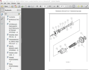
Chapter 14 – SUPERSTRUCTURE (INCLUDING SLEW MOTOR)
14.1 SUPERSTRUCTURE (INCLUDING SLEW MOTOR DATA) . . . 14-2
14.1.1 Superstructure (including slew motor) specifications 14-2
(28, up to Ser No. DBK0005010/31, up to Ser No. DBK0006026/35,
up to Ser No. DBK0007002)
14.1.2 Superstructure (including slew motor) torque data . . . . . . . . . . . . . . 14-2
(28, up to Ser No. DBK0005010/31, up to Ser No. DBK0006026/35,
up to Ser No. DBK0007002)
14.2 SUPERSTRUCTURE (INCLUDING SLEW MOTOR) MAINTENANCE
Principle of operation of slewing
Slew bearing
Slew motor (28, up to Ser No. DBK0005010/31, up to Ser No.
DBK0006026/35, up to Ser No. DBK0007002)
Reduction gear
Relief valve .
Parking brake
Timer valve .
Bypass valve
Slew motor (28, from Ser No. DBK0005010/31, from Ser No.
DBK0006026/35, from Ser No. DBK0007002)
Removing and installing the superstructure
Removing the superstructure
Installing the superstructure .
Removing and installing the control lever stands
Removing the control lever stands
Installing the control lever stands
Removing and installing the slew motor
Removing the slew motor
Installing the slew motor .
Removing and installing the slew bearing (ring)
Removing the slew bearing
Installing the slew bearing
14.2.6 Disassembling, inspecting, and assembling the slew motor.
Disassembling the slewing unit
Disassembling the hydraulic motor .
Disassembling the reduction gear
Inspecting the slewing unit . . .
Assembling the reduction gear .
Assembling the hydraulic motor
Assembling the slew unit . . . .
14.3 SUPERSTRUCTURE (INCLUDING SLEW MOTOR) TROUBLESHOOTING .
Slew motor does not tum
Slevving is not stable . . .
Slow speed slewing not possible
Oil leaking from joints
Chapter 15 – DECALS
15.1 SAFETY DECALS
15.2 MAINTENANCE
IMAGES PREVIEW OF THE MANUAL:
CASE 28 31 35 MINI EXCAVATOR SERVICE MANUAL 7-83260 – PDF DOWNLOAD:
PLEASE NOTE:
- This is the same manual used by the DEALERSHIPS to SERVICE your vehicle.
- The manual can be all yours – Once payment is complete, you will be taken to the download page from where you can download the manual. All in 2-5 minutes time!!
- Need any other service / repair / parts manual, please feel free to contact us at heydownloadss @gmail.com . We may surprise you with a nice offer
S.V