Case 650 Crawler Parts Catalog Manual 8-6010 – PDF DOWNLOAD
Original price was: $89.95.$28.95Current price is: $28.95.
Case 650 Crawler Parts Catalog Manual 8-6010 – PDF DOWNLOAD
Description
Case 650 Crawler Parts Catalog Manual 8-6010 – PDF DOWNLOAD
FILE DETAILS:
Case 650 Crawler Parts Catalog Manual 8-6010 – PDF DOWNLOAD
Language : English
Pages : 333
Downloadable : Yes
File Type : PDF
Size: 21.1 MB
TABLE OF CONTENTS:
Case 650 Crawler Parts Catalog Manual 8-6010 – PDF DOWNLOAD
A C
Adjuster – track …………………………………………. 5-7 Control Valve – equipment ………………… 8-47,8-49
Air Cleaner Control Valve Mounting – equipment.. ……….. 8-37
Assembly ……………………………………………. 2-45 Coolant Bottle – radiator …………………………… 2-39
Mounting …………………………………………….. 2-43 Cooling System – transmission …………………. 6-39
Air Restriction Indicator ……………………………. 2-47 Counterweights ………………………………………… 9-9
Alarm – backup ………………………………………. 4-29 Cover
Alternator Instrument Panel ………………………………….. 9-21
Assembly ……………………………………………… 4-7 Radiator Cap Access …………………………… 9-23
Mounting …………………………………………….. 4-17 Rear – battery access …………………………… 9-17
Pulley …………………………………………………… 4-7 Reservoir ………………………………………………. 8-5
Armrests …………………………………………. 9-31,9-33 Crankshaft – engine …………………………………. 2-27
Cushions – seat.. ……………………………… 9-31,9-35
B Cylinders
Backup Alarm …………………………………………. 4-29 Brake Master ………………………………………… 7-7
Battery – mounting and cables …………………. 4-15 Dozer Angle ………………………………………… 8-33
Battery Compartment ………………………………. 9-17 Dozer Lift ……………………………………………. 8-29
Belt Dozer Tilt. ……………………………………………. 8-31
Alternator ……………………………………………. 2-35 Ripper ………………………………………………… 8-35
Fan …………………………………………………….. 2-35 Cylinder Block – engine …………………….. 2-23,2-25
Seat. ……………………………………………. 9-31 , 9-33 Cylinder Head Covers ……………………………… 2-17
Blade – dozer …………………………………………… 9-5 Cylinder Sleeves – engine ………………………… 2-31
Block – engine cylinder …………………….. 2-23,2-25
Box – operators manual …………………………….. 8-5 D
Brakes Decals ……………………………………………. 9-47,9-49
Brake Assembly – transmission ……….. 7-9,7-11 Dipsticks
Cylinder – slave ……………………………………… 7-9 Engine Oil …………………………………………… 2-37
Hydraulic Lines ……………………………………… 7-5 Transmission Oil ……………………………………. 6-9
Lube Lines ……………………………………………. 7-9 Door – rear access ………………………………….. 9-1 7
Master Cylinder Assembly ………………………. 7-7 Dozer
Parking ……………………………………………….. 7-13 Blade ……………………………………………………. 9-5
Pedals – brake ………………………………………. 7-3 C-Frame ……………………………………………….. 9-3
Breather – transmission ……………………………… 6-9 Leveling Beam ………………………………………. 9-5
Brush Guard – ROPS ………………………………. 9-39 Drawbar …………. .-………………………………………. 9-9
Brush Screen – radiator ……………………………. 9-25 Drive – final, transmission ………………………… 6-27
Brush Screens – ROPS canopy ………………… 9-41 Drive Shaft Assembly ………………………………… 6-7
Drive Shaft Mounting …………………………………. 6-3
C
Camshaft – engine ………………………………….. 2-21 E
Canopy – ROPS ………………………………………. 9-39 Electrical System
Carrier Roller Assembly – track …………………. 5-13 Alarm – backup ……………………………………. 4-29
C-Frame – dozer ……………………………………….. 9-3 Alternator Assembly ………………………………. 4-7
Chain – track ……………………………………. 5-17,5-19 Cold Start. ……………. _. ……………………………. 4-33
Clutches – transmission …………………. 6-17 – 6-23 Front Wiring ………………………………………… 4-17
Cold Start System …………………………………… 4-33 Horn …………………………………………………… 4-31
Connecting Rods – engine ……………………….. 2-31 Instrument Panel Gauges ………………… 4-9,4-11
Controls Instrument Panel Wiring ……………………….. 4-13
Brake – Parking ……………………………………. 7-13 Lamp Assemblies …………………………. 4-25,4-27
Brake Pedals ………………………………………… 7-3 Lamp Wiring ………………………………… 4-21 ,4-23
Engine Throttle ……………………………………… 3-3 Rear Wiring …………………………………………. 4-19
Equipment ………………………………… 8-39 – 8-45 Starter Assembly ……………………………… 4-3,4-5
Forward, Reverse, and Steering ……………. 6-45 Engine Components
Control Tower – transmission ……………………. 6-47 Camshaft ……………………………………………. 2-21
Bur 8-6010 Issued March, 1990 Printed in U.S.A.
1-6 650 Crawler
ALPHABETICAL INDEX
E G
Engine Components-Cont. Guards-Cont.
Connecting Rods …………………………………. 2-31 Brush Screens – radiator ………………………. 9-25
Crankshaft ………………………………………….. 2-27 Brush Screens – ROPS canopy ……………… 9-41
Cylinder Block ………………………………. 2-23,2-25 Canopy Extension – ROPS ……………………. 9-41
Cylinder Head Cover ……………………………. 2-17 Hydraulic Lines – seat and tank frame ……. 9-15
Dipstick and Fill Tube …………………………… 2-37 Hydraulic Lines – see Hydraulic Circuit pages
Flywheel and Housing ………………………….. 2-29 Roll Over Protective Structure ………… 9-39,9-41
Front Gear Cover …………………………………… 2-5 Side Shields – engine …………………………… 9-27
Fuel Filter ……………………………………………. 3-11 Track – belly pans ………………………………… 5-15
Fuel Injection System …………………………….. 3-9 Transmission – rear ……………………………… 9-13
Gasket Kits …………………………………………. 2-33 Undercarriage ……………………………………… 9-13
Injection Nozzle …………………………………… 3-15
Injection Pump and Drive ……………………… 3-13 H
Manifolds – intake and exhaust.. ……………… 2-7 Harness
Oil Filter and Cooler …………………………….. 2-13 Front ………………………………………………….. 4-17
Oil Pump and Pan ……………………………….. 2-15 Instrument Panel ………………………………….. 4-13
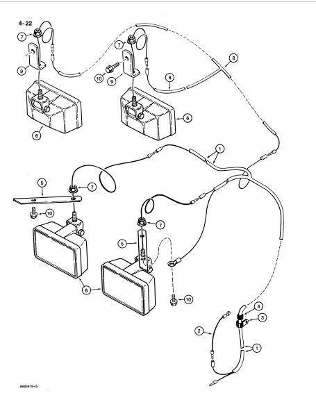
Pistons ……………………………………………….. 2-31 Lamps …………………………………………. 4-21,4-23
Turbocharger System ……………………… 2-9,2-11 Rear …………………………………………………… 4-19
Valve Mechanism ………………………………… 2-19 Head – engine cylinder …………………………….. 2-19
Water Pump System ………………………………. 2-3 Head Lamps ……………………………………. 4-25,4-27
Engine Frame and Mounting ……………………. 9-11 Headliner – ROPS canopy ………………………… 9-43
Engine Mounting …………………………………….. 2-35 Heel Plate ………………………………………………. 6-4 7
Equipment Control Valves ………………. 8-47 – 8-59 Hood ……………………………………………………… 9-19
Exhaust – stack and muffler ……………………… 2-49 Hook – pull. ……………………………………….. 9-9,9-11
Horn ………………………………………………………. 4-31
F Hydraulic Circuits
Fan – radiator …………………………………………. 2-35 Brakes – lube lines …………………………………. 7-9
Filters Brakes – master cylinder ………………………… 7-5
Air Cleaner ………………………………………….. 2-45 Dozer Angle ………………………….. 8-17,8-19,8-23
Fuel ……………………………………………………. 3-11 Dozer Lift …………………………………….. 8-13,8-15
Oil – engine …………………………………………. 2-13 Dozer Tilt.. …………………………….. 8-17,8-19,8-21
Oil – equipment.. ……………………………………. 8-3 Equipment – supply and return ………….. 8-7,8-9
Oil – transmission ………………………………… 6-43 Ripper …………………………………………. 8-25,8-27
Final Drive – transmission ………………………… 6-27 Torque Converter to Transmission …………. 6-35
Floor Plates ……………………………………………. 9-29 Transmission Control Valve …………………… 6-29
Flywheel and Housing – engine ………………… 2-29 Transmission Cooling …………………………… 6-39
Frames Transmission Suction Line ……………………. 6-37
C-frame – dozer …………………………………….. 9-3 Hydraulic Reservoir and Covers ……………. 8-3,8-5
Main – chassis …………………………………….. 9-11
Reservoir – hydraulic ………………………………. 8-3
Seat and Tank …………………………………….. 9-15 Idler Assembly – track ……………………………….. 5-9
Track ……………………………………………………. 5-3 Idler Mounting ………………………………………….. 5-5
Fuel Injection System ………………………………… 3-9 Index – numerical ……………………………………. 10-2
Fuel Lines – tank to engine ………………………… 3-7 Injection System – fuel. ………………………………. 3-9
Fuel Tank …………………………………………………. 3-5 Instrument Panel ……………………………….. 4-9 ,4-11
Instrument Panel Cover ……………………………. 9-21
G
Gaskets – engine …………………………………….. 2-33 L
Gauges – instrument panel …………………. 4-9,4-11 Lamps
Grille – radiator ……………………………………….. 9-25 Halogen ……………………………………………… 4-27
Grousers – track shoes ……………………………. 5-21 Incandescent ………………………………………. 4-25
Guards Instrument Panel ………………………………….. 4-13
Bur 8-6010 Issued March, 1990 Printed in U.S.A.
650 Crawler
ALPHABETICAL INDEX
1-7
L R
Leveling Beam – blade ………………………………. 9-5 Reservoir – hydraulic …………………………………. 8-3
Leveling Gauge – dozer blade …………….. 8-21 ,9-5 Restriction Indicator – air cleaner ………………. 2-4 7
Levers – see Controls Ripper ……………………………………………………… 9-7
Rock Guards – track ………………………………… 5-15
M Rocker Arms – engine ……………………………… 2-19
Main Frame ……………………………………………. 9-11 Rods – connecting, engine ………………………. 2-31
Manifold – engine ……………………………………… 2-7 Rods – push, engine ……………………………….. 2-19
Manual Box – operators …………………………….. 8-5 Roll Over Protective Structure …………………… 9-39
Master Cylinder – brake …………………………….. 7-7 Rollers – track ………………………………….. 5-11,5-13
Modulator Valve – transmission ………………… 6-33
Muffler – exhaust …………………………………….. 2-49 s
Screens
N Radiator – grille ……………………………………. 9-25
Noise Reduction Pads ……………………… 9-43,9-45 ROPS Canopy – brush guards ……….. 9-39,9-41
Nozzle – fuel injector ……………………………….. 3-15 Seat Assembly
Numerical Index ……………………………………… 10-2 Standard …………………………………………….. 9-31
Suspension ………………………………….. 9-35,9-37
0 Seat Belts ……………………………………….. 9-31,9-33
Oil Cooler – engine ………………………………….. 2-13 Seat Mounting …………………………………. 9-31,9-33
Oil Pan – engine ……………………………………… 2-15 Serial Number Locations ……………………………. 1-2
Oil Pump – engine …………………………………… 2-15 Shoes – track ………………………………………….. 5-21
Oil Pump – equipment.. ……………………………. 8-11 Shroud – radiator …………………………………….. 2-41
Operators Manual Box ………………………………. 8-5 Side Shields – engine ………………………………. 9-27
Sleeves – piston ……………………………………… 2-31
p Sprocket – track drive ………………………………… 5-3
Pads – noise reduction ……………………… 9-43,9-45 Starter Assembly …………………………………. 4-3,4-5
Parking Brake …………………………………………. 7-13 Starter Mounting ……………………………………… 4-15
Pedal – brake ……………………………………………. 7-3 Step Plates …………………………………………….. 9-29
Pedal – throttle control.. ……………………………… 3-3 Switches
Pistons – engine ……………………………………… 2-31 Cold Start ……………………………………………. 4-13
Plates – floor and step …………………………….. 9-29 Disconnect – master …………………………….. 4-15
Pull Hook ………………………………………….. 9-9,9-11 Horn ……………………………………………. 4-13,4-31
Pulley Lamp ………………………………………………….. 4-13
Alternator ……………………………………………… 4-7 Oil Pressure – engine ……………………. .4-11,4-13
Crankshaft ………………………………………….. 2-27 Pressure – backup alarm ………………………. 4-29
Fan ………………………………………………………. 2-3 Starter ………………………………………………… 4-19
Pump – water ………………………………………… 2-3
Pumps T
Equipment ………………………………………….. 8-11 Tank
Fuel Injection – engine ………………………….. 3-13 Fuel ……………………………………………………… 3-5
Oil – engine …………………………………………. 2-15 Hydraulic Oil …………………………………………. 8-3
Oil – equipment ……………………………………. 8-11 Thermal Bypass Valve – cooling system ……. 6-41
Transmission ………………………………………… 6-5 Throttle Controls ……………………………………….. 3-3
Water – engine ………………………………………. 2-3 Torque Converter ……………………………………… 6-3
Torque Converter Housing …………………………. 6-5
R Torque Converter Mounting ……………………….. 6-3
Radiator Assembly ………………………………….. 2-41 Tower – control, transmission …………………… 6-47
Radiator Cap Access Cover …………………….. 9-23 Track
Radiator Mounting …………………………………… 2-39 Adjuster Assembly …………………………………. 5-7
Recoil System – track ………………………………… 5-3 Adjuster Mounting …………………………………. 5-5
Recovery Bottle – radiator coolant.. …………… 2-39 Carrier Roller ……………………………………….. 5-13
Regulator – voltage, alternator ……………………. 4-7 Chain ………………………………………….. 5-17,5-19
Bur 8-6010 Issued March, 1990 Printed in U.SA
1-8 650 Crawler
ALPHABETICAL INDEX
T
Track-Cont.
Frames …………………………………………………. 5-3
Guards ……………………………………………….. 5-15
Idler Assembly ………………………………………. 5-9
Idler Mounting ……………………………………….. 5-5
Recoil Housing ……………………………………… 5-3
Rollers ………………………………………………… 5-11
Shoes …………………………………………………. 5-21
Sprocket ………………………………………………. 5-3
Transmission Assembly
Bevel Pinion Shaft and Gear …………………. 6-25
Brakes …………………………………………… 7-9,7-11
Bypass Valve Assembly ……………………….. 6-41
Clutch Assemblies ……………………… 6-17 – 6-23
Clutch Shafts ……………………………….. 6-17,6-19
Control Tower ……………………………………… 6-4 7
Control Valve Assembly ……………………….. 6-31
Covers
Front. ………………………………………………. 6-11
Rear ………………………………………………… 6-13
Dipstick and Fill Tube …………………………….. 6-9
Filters …………………………………………………. 6-43
Final Drive …………………………………………… 6-27
Fluid Recovery Bottle …………………………….. 6-9
Housing ……………………………………………… 6-11
Hydraulic Lines – control valve ………………. 6-29
Levers – control. …………………………………… 6-45
Lubrication Lines – brakes ………………………. 7-9
Main Shaft …………………………………………… 6-17
Modulator Valve Assembly ……………………. 6-33
Range Shift …………………………………………. 6-15
Transmission Mounting ……………………………… 6-9
Turbocharger System – engine ……………. 2-9,2-11
u
Undercarriage Guards – belly pans …………… 9-13
V
Valve
Equipment Control
Auxiliary Section ……………………………….. 8-55
Circuit Relief …………………………………….. 8-59
Four Spool ………………………………………. 8-49
Lift Section ………………………………………. 8-53
Load Check …………………………………….. 8-57
Main Relief ………………………………………. 8-51
Mounting …………………………………………. 8-37
Three Spool …………………………………….. 8-4 7
Modulator – transmission ……………………… 6-33
Pressure Sensing – transmission …………… 6-39
Relief – transmission …………………………….. 6-35
Thermal Bypass – transmission ……………… 6-41
V
Valve-Cont.
Transmission Control… …………………………. 6-31
Valve Mechanism – engine ……………………….. 2-19
Voltage Regulator – alternator …………………….. 4-7
w
Wiring
Instrument Panel ………………………………….. 4-13
Tractor ………………………………………. 4-17 – 4-33
IMAGES PREVIEW OF THE MANUAL:
CASE 650 CRAWLER PARTS CATALOG MANUAL 8-6010 – PDF DOWNLOAD:
PLEASE NOTE:
- This is not a physical manual but a digital manual – meaning no physical copy will be couriered to you. The manual can be yours in the next 2 mins as once you make the payment, you will be directed to the download page IMMEDIATELY.
- This is the same manual used by the dealers inorder to diagnose your vehicle of its faults.
- Require some other service manual or have any queries: please WRITE to us at [email protected]
S.V