CASE 721E TIER 4 WHEEL LOADER SERVICE REPAIR MANUAL (84488413) CASE 721E TIER 4 – PDF Download
Original price was: $81.95.$36.95Current price is: $36.95.
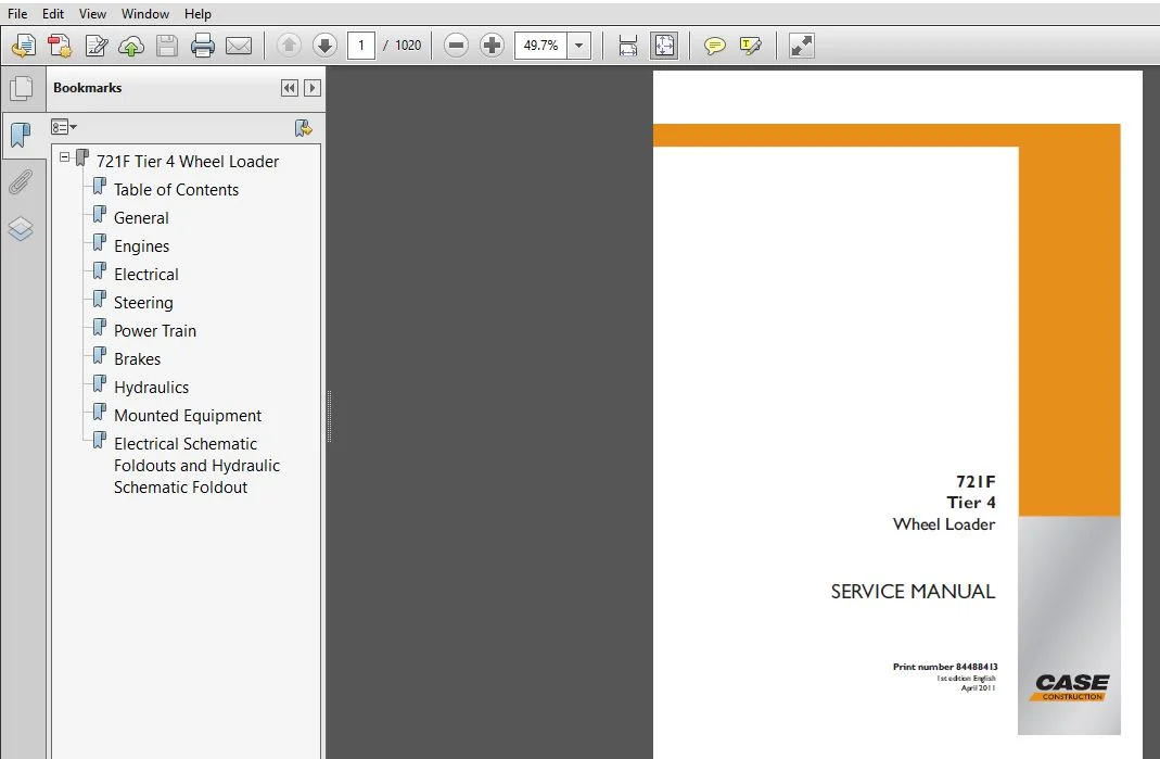
Case Wheel Loader 721F Tier 4 Service Manual_84243980R0
Size : 94.8 MB
Format : PDF
Language : English
Brand: Case
Type of machine: Case Wheel Loader
Type of document: Service Manual
Model: Case Wheel Loader 721F Tier 4
Part No:84488413
Description
CASE 721E TIER 4 WHEEL LOADER SERVICE REPAIR MANUAL (84488413) CASE 721E TIER 4
File Details:
Case Wheel Loader 721F Tier 4 Service Manual_84243980R0
Size : 94.8 MB
Format : PDF
Language : English
Brand: Case
Type of machine: Case Wheel Loader
Type of document: Service Manual
Model: Case Wheel Loader 721F Tier 4
Part No:84488413
CASE 721E TIER 4 WHEEL LOADER SERVICE REPAIR MANUAL (84488413) CASE 721E TIER 4 – PDF DOWNLOAD:
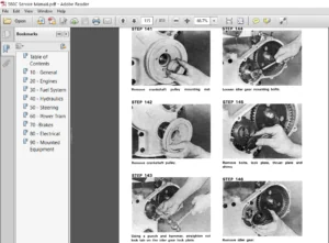
Image Preview:
Sample Page From The Manual:
CASE 721E TIER 4 WHEEL LOADER SERVICE REPAIR MANUAL (84488413) CASE 721E TIER 4
1. Check the oil level in the hydraulic reservoir; add oil as necessary.
2. Push and release the brake pedal many times with the engine stopped to remove all hydraulic pressure from the brake system until there is no pressure on the pedal.
3. Install two 207 bar (3000 psi) pressure gauges to front and rear hydraulic brake accumulator test ports, refer to page 7 for the locations of the test ports.
4. Make sure that the pressure gauge hoses are long enough so the gauges can be read while sitting in the operators seat.
5. Start the engine. Run the engine at low idle while reading the pressure gauges. The alarms (buzzer, master warning light and brake pressure warning light) should shut off when the accumulator with the lowest pressure reaches 106 to 115 bar (1530 to 1670 psi), approximately 40 seconds at any engine speed.
6. After the alarms stop, run the machine at high idle to finish charging the accumulators. The pressure must increase on both gauges until 190 to 196 bar (2757 to 2843 psi) is reached. This is the accumulator valve cut-out pressure. It is normal for the pressure to drop slightly once the cut-out pressure is reached.
7. With the engine running at high idle, push and release the brake pedal rapidly while reading the drop in pressure on the gauges. The pressure drops may not be equal, but as the lowest pressure reaches 157 to 167 bar (2280 to 2420 psi), the system pressure must start to increase. This is the valve cut in pressure.
Tabe of Contents:
CASE 721E TIER 4 WHEEL LOADER SERVICE REPAIR MANUAL (84488413) CASE 721E TIER 4
General
General Torque Specifications 1001
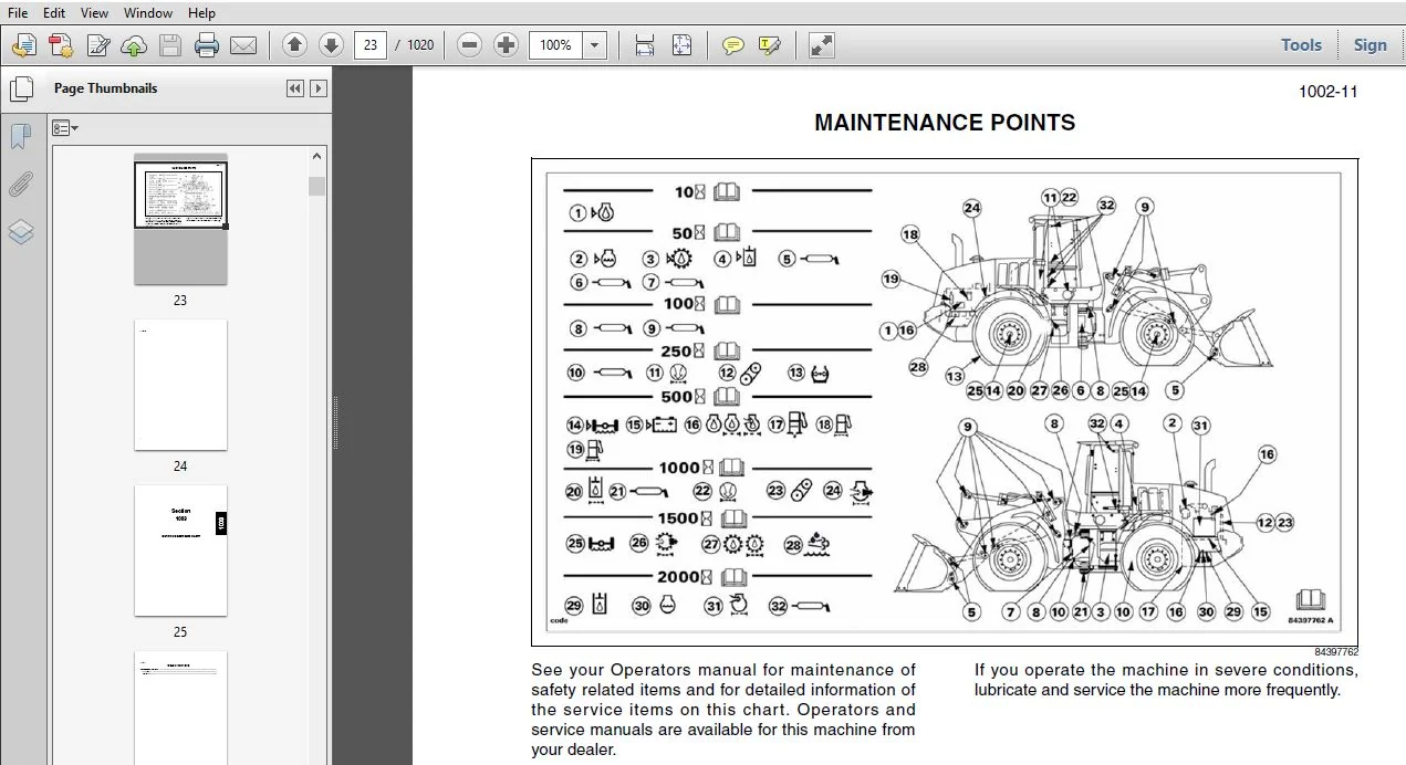
Fluids and Lubricants 1002
Metric Conversion Chart 1003
Engines
Engine and Radiator Removal and Installation 2000
Stall Tests 2002
After Cooler 2003
Engine Intake Air Filtration 2010
SCR System Sensors 2020
SCR Catalyst 2030
Engine Intake Temperature/Humidity Sensor 2040
DEF/ADBLUE Heater Control Valve 2050
DEF/ADBLUE DNOx Supply Module 2060
DEF/ADBLUE Dosing Injector 2070
DEF/ADBLUE Supply Tank 2080
DEF/ADBLUE Supply Tank Level and Temperature Sensor/Pick-up and Heater 2090
DEF/ADBLUE Supply Filters 2100
For Engine Repair, See the Engine Service Manual (sold separately) 84392428
Fuel System
For Fuel System Repair, See the Engine Service Manual (sold separately) 84392428
Electrical
Removal and Installation of Starter and Alternator 4001
Electrical Specifications and Troubleshooting 4002
Batteries 4003
Instrument Cluster 4005
Steering
Removal and Installation of Steering Components 5001
Steering Specifications, Pressure Checks, and Troubleshooting 5002
Steering Cylinders 5005
Center Pivot 5006
Auxiliary Steering Motor and Pump 5008
Joystick Steering System (JSS) 5009
Power Train
Removal and Installation of Power Train Components 6001
Transmission Specifications, Pressure Checks, and Troubleshooting 6002
4 & 5 Speed Transmission 6003
Multitrac MT-L 3705 II / 3085 II / 3095 II Axles 6004
Drive Shafts, Center Bearing, and Universal Joints 6005
Wheels and Tires 6006
Brakes
Removal and Installation of Brake Components 7001
Hydraulic Brake Troubleshooting 7002
Brake Pump 7003
Brake Accumulators 7004
Parking Brake 7008
Hydraulics
Removal and Installation of Hydraulic Components 8001
Hydraulic Specifications, Troubleshooting, and Pressure Checks 8002
Cleaning the Hydraulic System 8003
Hydraulic Pump 8004
Hydraulics (continued)
Loader Control Valve 8005
Cylinders 8006
Coupler Solenoid Locking Valve 8007
Ride Control Accumulator 8013
Ride Control Valve 8014
Mounted Equipment
Air Conditioning Troubleshooting and System Checks For Systems with HFC-134a
Refrigerant 9002
Air Conditioner System Service 9003
Removal And Installation Of Air Conditioning And Heater Components 9004
Loader 9006
Roll Over Protective Structure (ROPS), Cab Structural Frame (CSF) 9007
Cab Glass Installation 9010
Rear View Camera Installation and Removal 9020
Electrical Schematic Foldouts and Hydraulic Schematic Foldout In Rear Pocket
Please Note:
- This is the SAME manual used by the dealers to troubleshoot any faults in your vehicle. This can be yours in 2 minutes after the payment is made.
- Contact us at [email protected] should you have any queries before your purchase or that you need any other service / repair / parts operators manual.